Expansion and contraction theoretically takes place longitudinally from the centre of the sheet outwards. Therefore, the degree of expansion and contraction is greater at the ends of the sheet, where it is approximately half of the total amount. Lateral expansion is negligible due to the general design of profiles.
The maximum distance between the top and bottom rows for screw fix decks should only be 24m for roofs and 15m for walling. In excess of these recommended maximum lengths, the expansion and contraction elongates screw holes, rendering the neoprene washers ineffective and possibly causing the screws to shear. Thus, for pierce fix roofs, step joints are required where lengths exceed 24m (see “Long Length Roofing Solutions”). For lengths of roofs greater than 24m, concealed decks are recommended as they will remove the need for step joints, which can be a cause of leaks in the roof.
Table DD TEC SS 001 and Table DD TEC SS 002 show the degree of expansion and contraction of steel and stainless steel sheeting through various temperature changes.
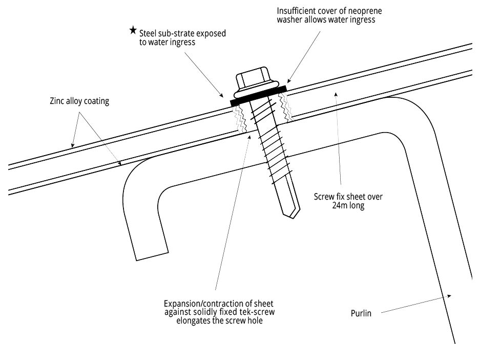
Figure DD TEC PFR 001 - Elongated Screw Hole
Note:
Diagram not to scale.
★ Lighter colours expand and contract at a less significant rate than darker colours, so on occasions longer sheet lengths for pierce fix roofs may be possible. Please contact your local Fielders® representative for clarification.
Expansion/Contraction of Steel and Stainless Steel
Steel
| Sheet Length (m) | Temperature Change | ||
| 10° C | 30° C | 50° C | |
| 10 | 1.20 mm | 3.60 mm | 6.00 mm |
| 20 | 2.40 mm | 7.20 mm | 12.00 mm |
| 30 | 3.60 mm | 10.80 mm | 18.00 mm |
| 50 | 6.00 mm | 18.00 mm | 30.00 mm |
| 75 | 9.00 mm | 24.00 mm | 45.00 mm |
| 100 | 12.00 mm | 36.00 mm | 80.00 mm |
Note:
Fielders® HiKlip® 630 and KingKlip 700® allow for expansion and contraction as the decks slide over the clip, enabling sheets of any length to be used.
Stainless Steel
| Sheet Length (m) | Temperature Change | ||
| 10° C | 30° C | 50° C | |
| 10 | 1.70 mm | 5.10 mm | 8.50 mm |
| 20 | 3.40 mm | 10.20 mm | 17.00 mm |
| 30 | 5.10 mm | 15.30 mm | 25.50 mm |
| 50 | 8.50 mm | 25.50 mm | 42.50 mm |
| 75 | 12.75 mm | 38.25 mm | 63.75 mm |
| 100 | 17.00 mm | 51.00 mm | 85.00 mm |
Note:
Fielders® HiKlip® 630 and KingKlip 700® allow for expansion and contraction as the decks slide over the clip, enabling sheets of any length to be used.
For the changes in length due to expansion and contraction for other roofing material, simply use the following formula:
ΔL = α Li ΔT
105
where ΔL = change in length due to thermal expansion/contraction (mm)
Δ = linear expansion coefficient for other materials
Li = initial length of the sheeting (mm)
ΔT = change in temperature (°C)
Table “DD TEC LEC 001” shows the values of the linear expansion coefficient (α) for various other roofing materials.
Following are some examples of changes in length due to expansion/contraction for other materials.
The Caterpillar Effect
The caterpillar effect is a theoretical phenomenon that describes the process whereby expansion takes place mono-directionally i.e. the material does not resort to its original position when contraction takes place but rather moves in one direction after each expansion/contraction cycle. Therefore it has the potential to ‘work its way’ off the clip and subsequently off the roof. It is relevant only to concealed fix decks where the roof sheet is held in place by a clip and the expansion and contraction process is managed by the profile sliding over the fixing clip.
Fielders® have installed many long length roofs up to 102m and have never encountered the problem of the caterpillar effect. However if a building designer has concerns the following method can be used:
Fixed-point screws should be installed at the ridge and hip. At pitches of less than 5°, a shallow head screw is installed through the male rib into the clip and covered by the female rib. At pitches over 5°, a hexagonal-headed screw with a bonded washer is installed into the ridge spacer in the centre of each pan. It should be hidden by a ridge flashing where possible.
The end of a sheet must be turned down by 20° at eaves/valleys, using the correct end of the tool supplied, even on a 1° pitch roof this permits good water run-off, prevents run-back under the sheet and laterally stiffens the pan. Turn-down must be carried out to all sheets, irrespective of pitch.
For additional security, the interlocking ribs can be riveted together through the rib head, 5mm from the sheet end at the eaves/valleys position.
