Features and Benefits
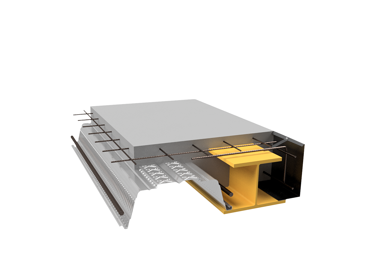
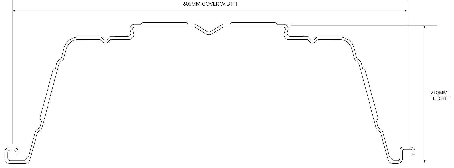
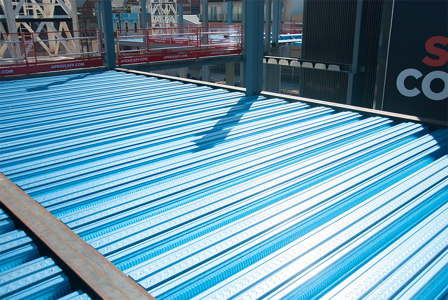
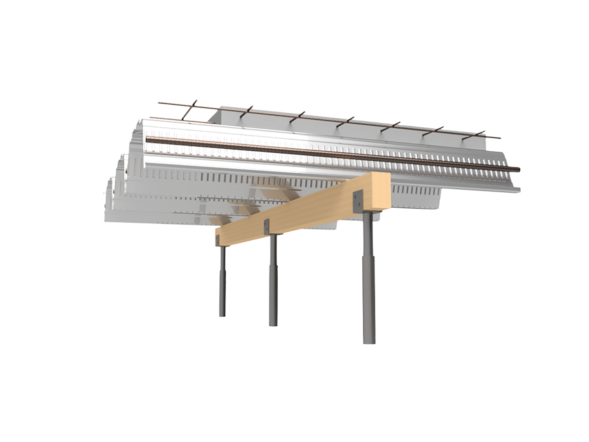
SlimDek 210®, from the Fielders KingFlor® range, is a new deep deck composite floor system. As a result of the large depth and effective cross sectional area, SlimDek 210® is capable of achieving unprecedented unpropped spans of up to 7.0 metres and propped spans up to 10.0 metres. Additional benefits of this system are realised when implemented using SlimFlor® construction, achieved by combining the SlimDek 210® profile with universal beam or universal column, or similar, with a suitable bottom flange seating plate to result in a total structural floor zone as little as 300mm.
| Feature | Benefit |
| Unique profile | Concrete savings of up to 60% when compared to alternative formwork products |
| Less concrete by volume | Lower overall dead load of flooring, and reduced frame and foundation loads |
| Large unpropped spans | Less propping congestion and easy access to the underside of the slab |
| ReLokTM Features | A strong mechanical interlock with the concrete slab resulting in stronger composite strength. |
| SlimFlor® construction | Floor system depths as low as 280mm |
Concrete Savings
SlimDek 210® effectively saves 160mm of concrete off the overall slab depth when compared to conventional concrete slabs. This represents significant savings in concrete costs, supporting framework and foundation loads.
Material Specifications
KingFlor® SlimDek 210® decking is manufactured as standard from either G550 (550MPa Yield Strength) 1.0mm Base Metal Thickness (BMT), G500 1.2mm BMT or G450 1.5mm steel. The galvanised coating thickness for all three is Z350 (minimum 350g/m2) in accordance with AS 1397-2011.
Installing SlimDek 210®
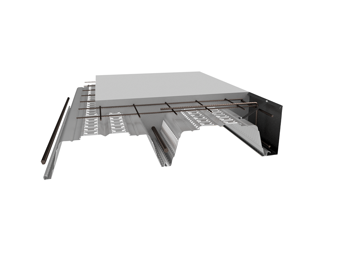
Edge Infill/End Diaphragms
Galvanised steel edge diaphragms for the SlimDek 210® profile are installed prior to laying the sheets when using the SlimFlor® system. The end diaphragm aligns with the edge of the lower flange of the beam and aids in achieving the beams fire rating including fixings.
Laying SlimDek 210®
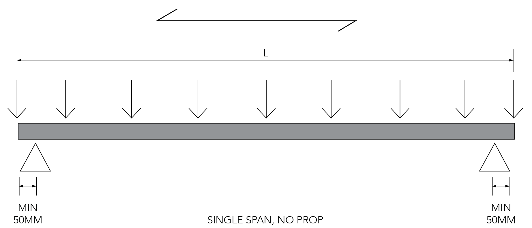
- Place the SlimDek 210® sheets on the asymmetric beam or beam fitted with an additional bottom flange seating plate ensuring minimum 50mm bearing is achieved. In the situation where SlimDek 210® is supported by a brick or masonry wall, a separating strip such as Malthoid is recommended.
- Engage subsequent sheets of SlimDek 210® by locking the larger female rib over the male rib as shown.
- Once engaged, the SlimDek 210® side laps are to be stitched at 500mm with 10-16 Tek screws.
Fasteners and Locations
The decking must be positively fixed to the supporting floor beam or wall, with a diaphragm, in order to avoid movement and excessive deflection during the pouring of concrete. When fixing to a steel support structure, shot fired pins or self drilling/tapping fasteners should be used with the diaphragm. Provide one fixing at each diaphragm at every sheet plus two fasteners in the top of the SlimDek 210® sheet to the diaphragm. In the case of other support systems, such as brickwork, blockwork and concrete, the SlimDek 210® must be fixed using pre drilled holes and self tapping fixings suitable for masonry or concrete. A diaphragm must be used at all supports for the Slimdek 210® sheeting to be supported on.
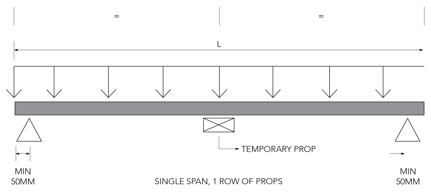
Temporary Propping
If temporary propping is required [refer to the quick reference tables on the back page], they should be placed at the correct centres prior to laying the SlimDek 210® sheets. Generally timber or steel bearers with a minimum dimension of 100mm x 100mm are used on vertical props. The props should be installed so as to prevent settlement during loading by wet concrete and other construction loads. Temporary props should only be removed after the slab has reached sufficient strength [at least 75% of the specified 28 day strength]. The full design load may only be applied once the slab has achieved its 28 day strength.
Reinforcement
Place all reinforcement in strict accordance with the Structural Engineers drawings and specification. The decking becomes part of the slab reinforcement with the remainder formed by a bar in each decking trough and a mesh placed near the slab top. Normally, circular plastic spacers position the bars 70mm from the base of the trough. This distance can increase to 90 or 120mm respectively when 90 or 120 minutes fire resistance is required.
Concrete Placement
The specified grade of concrete and any chemical admixtures must be in strict accordance with AS3600 and the Structural Engineers drawings and specification. The deck must be clear of any excess dirt, grease or debris as this inhibits bonding between the deck and concrete. Ensure that concrete is applied evenly over the decking surface, as mounding of the wet concrete will cause excessive local loading.


Single Slab Span (L) on Steel Support (mm) Formwork Deflection Limit L/130
| Slab Depth (mm) D | 1.00 BMT No. of props per span | 1.20 BMT No. of props per span | 1.50 BMT No. of props per span |
|||
| 0 | 1 | 0 | 1 | 0 | 1 | |
| 280 | 5350 | 9400 | 6200 | 10520 | 7000 | N/A |
| 290 | 5200 | 9040 | 6050 | 10240 | 6800 | N/A |
| 300 | 5050 | 8760 | 5900 | 10000 | 6650 | [111680] |
| 310 | 4900 | 8440 | 5600 | 9760 | 6500 | 11440 |
| 320 | 4750 | 8160 | 5400 | 9520 | 6400 | [11640] |
| 330 | 4650 | 7880 | 5300 | 9320 | 6250 | 11400 |
| 340 | 4550 | 7640 | 5150 | 9120 | 6150 | 11160 |
| 350 | 4450 | 7400 | 5050 | 8920 | 6050 | 10960 |
| 360 | 4350 | 7200 | 4950 | 8760 | 5900 | 10760 |
| 370 | 4250 | 7000 | 4850 | 8560 | 5800 | 10560 |
| 380 | 4150 | 6800 | 4750 | 8400 | 5700 | 10400 |
| 390 | 4050 | 6640 | 4650 | 8240 | 5650 | 10240 |
| 400 | 4000 | 6520 | 4600 | 8080 | 5550 | 10080 |
Note: Span values that are equal in both tables are governed by strength
Single Slab Span (L) on Steel Support (mm) Formwork Deflection Limit L/240
| Slab Depth (mm) D | 1.00 BMT No. of props per span | 1.20 BMT No. of props per span | 1.50 BMT No. of props per span |
|||
| 0 | 1 | 0 | 1 | 0 | 1 | |
| 280 | 5350 | 99400 | 5800 | 10520 | 6150 | N/A |
| 290 | 5200 | 9040 | 5650 | 10240 | 6000 | N/A |
| 300 | 5050 | 8760 | 5500 | 10000 | 5900 | N/A |
| 310 | 4900 | 8440 | 5400 | 99760 | 5750 | N/A |
| 320 | 4750 | 8160 | 5250 | 9520 | 5650 | [11640] |
| 330 | 4650 | 7880 | 5150 | 9320 | 5550 | 11400 |
| 340 | 4550 | 7640 | 5050 | 9120 | 5450 | 11160 |
| 350 | 4450 | 7400 | 4950 | 8920 | 5350 | 10960 |
| 360 | 4350 | 7200 | 4900 | 8760 | 5250 | 10760 |
| 370 | 4250 | 7000 | 4800 | 8560 | 5150 | 10560 |
| 380 | 4150 | 6800 | 4750 | 8400 | 5100 | 10400 |
| 390 | 4050 | 6640 | 4650 | 8240 | 5000 | 10240 |
| 400 | 4000 | 6520 | 4600 | 8080 | 4950 | 10080 |
Design Assumptions
- Concrete density: 24kN/m3
- SlimDek 210® strength and serviceability capacities are based on full scale test results.
- An additional concrete weight due to ponding of (0.7x deflection limit) 24.0kN/m3 has been considered for strength and serviceability limit states.
- The spans in the above table include a minimum bearing width of 50mm on each end support.
- Supports shall be effectively rigid and strong to support construction loads.
- Do not cantilever SlimDek 210® over end supports.
- The information contained in this publication is intended for guidance only. This information should only be use by a qualified structural engineer.
- The practical limit for span to slab depth ratio is considered to be 35 for single spans, values above these limits are listed in [ ] brackets.
- Side laps of SlimDek 210® need to be stitched by metal screws at 500mm intervals.
- The spans in the tables are based on the condition that SlimDek 210® sheets are fixed to the end diaphagms as per Fielder’s typical details.
- Construction live loads used for the formwork span tables are in accordance with AS/NZS 2327:2017 Appendix A Stage 2: 1.0kPa Workmen and equipment and; 2.5kPa Stacked materials (to be clearly stated on construction drawings) Stage 3: 1.0kPa Workmen and equipment or; 2.0kPa Mounding of concrete over an area of 1.6 x 1.6m2
- The values in the tables do not consider axial loading on the sheeting.