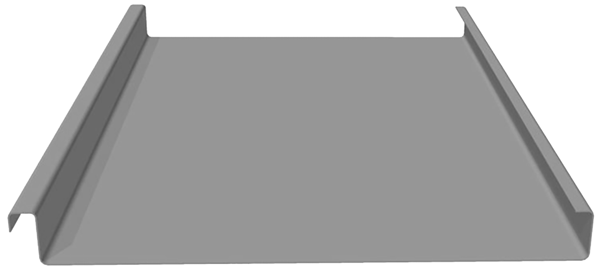
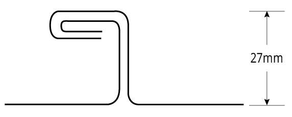
Single Seam
Rainfall Capacity
For further information, please refer to sections “Rainfall Intensity” and “Water Carrying Capacity and Rainwater Run-Off”.
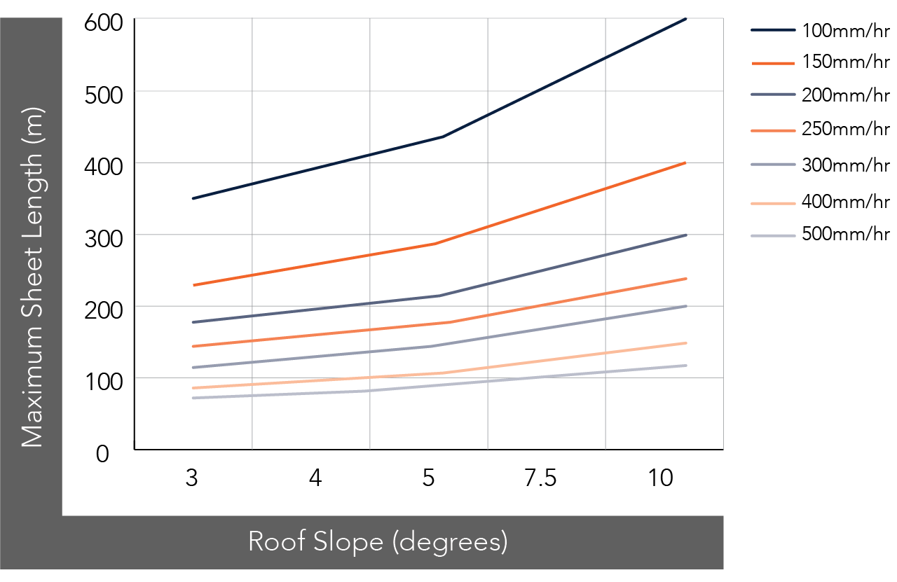
Figure GR (325 & 525) RC NC 001
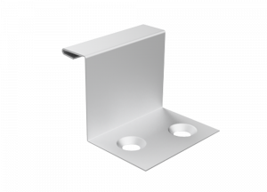
Figure GR CL NC 001 Grandeur® Fixed Clip
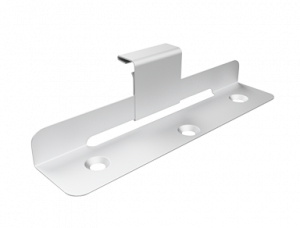
Figure GR CL NC 002 Grandeur® Sliding Clip
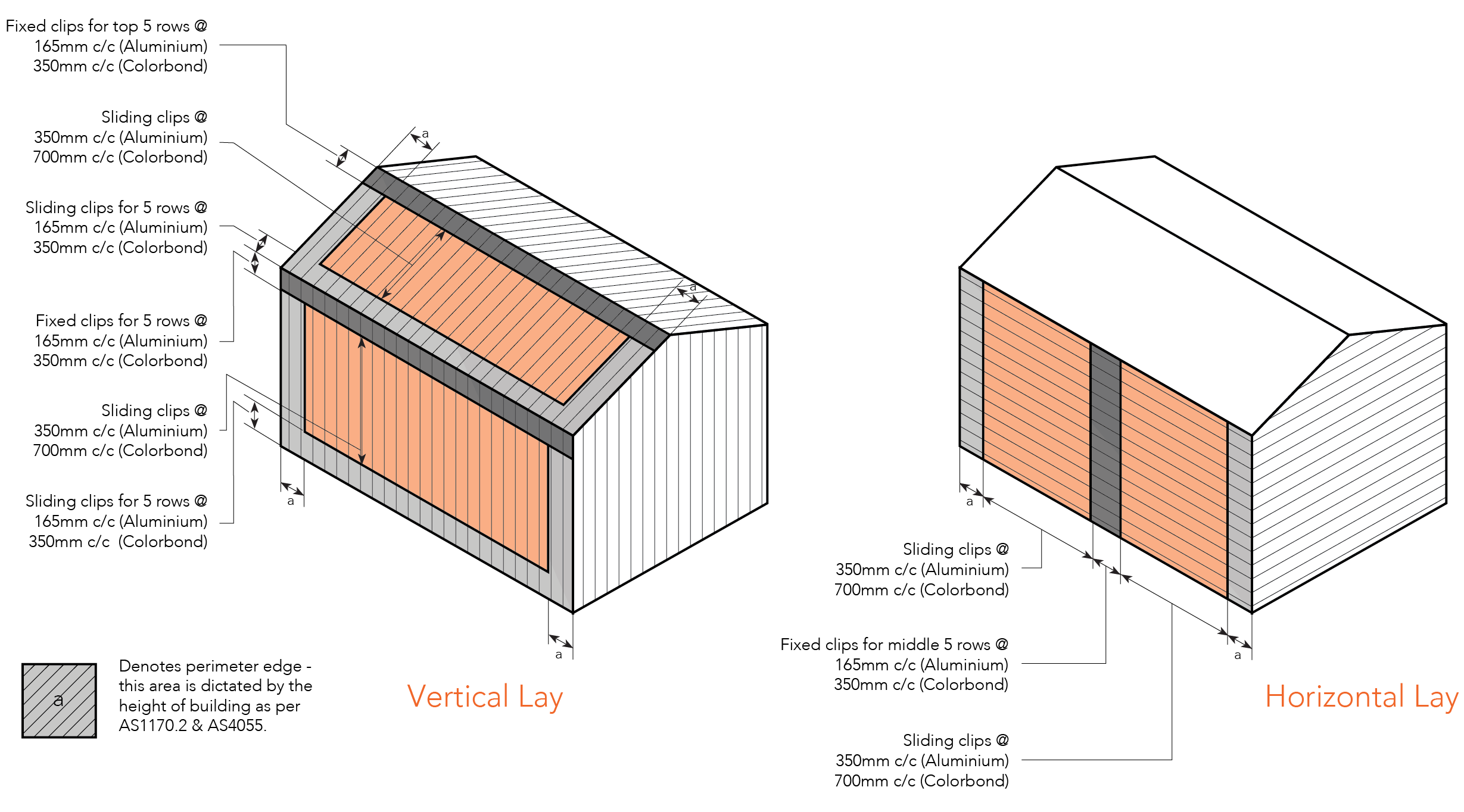
Figure GR ID NC 001
Please note: “a” may be calculated as:
Overall building length (OBL) x 0.2. - If OBL x 0.2 < 1200mm then 1200mm shall apply
Average building height (ABH) x 0.2. - If ABH x 0.2 < 1200mm then 1200mm shall apply
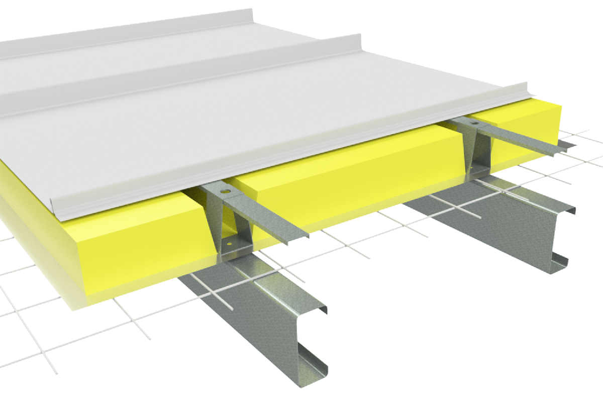
GR INS NC 001
Note:
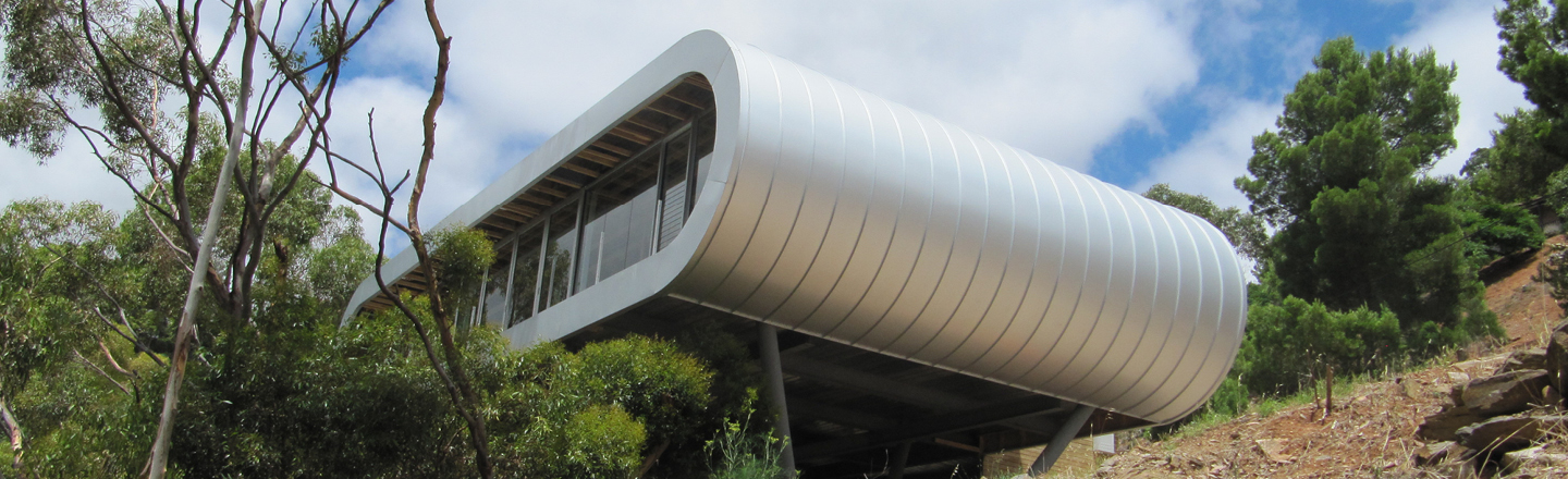
Image displayed using Shadowline profile
Typical Roof Cladding Setout - Unsupported - Plan View
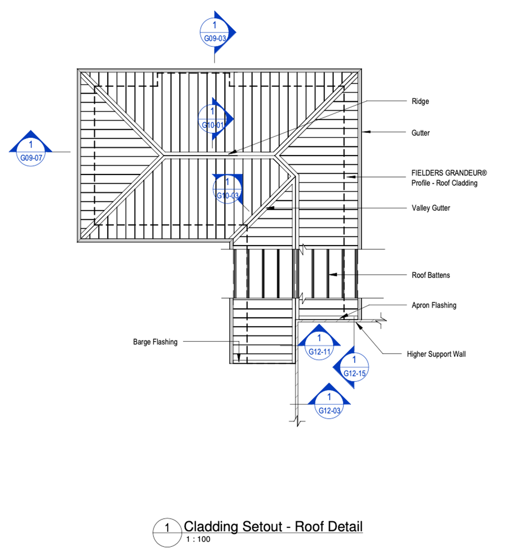
Figure GR ID NC - G04-09 - Typical Roof Cladding Setout - Unsupported - Plan View
Ridge Detail - Unsupported - Panel
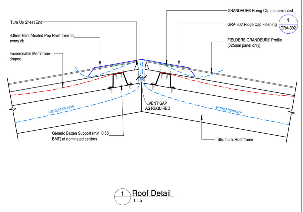
Figure GR ID NC - G10-01 - Ridge Detail - Unsupported - Panel
Valley Detail - Unsupported - Panel
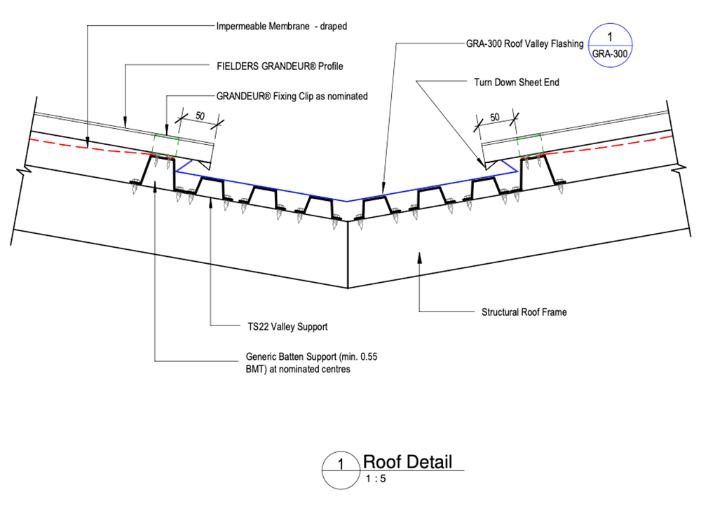
Figure GR ID NC - G10-03 - Valley Detail - Unsupported - Panel
Parapet Wall Detail - Unsupported - Panel - Vertical Fix
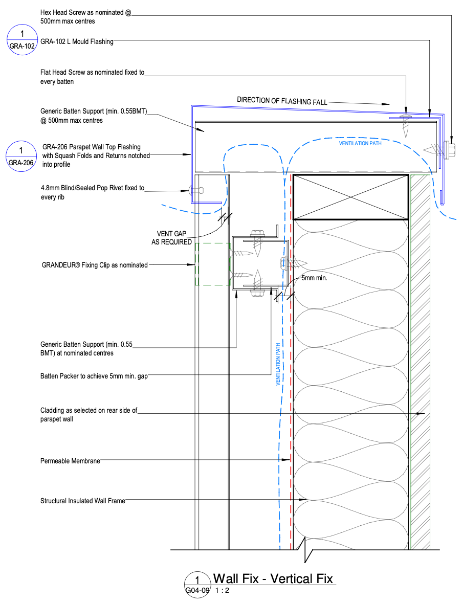
Figure GR ID NC - G12-03 - Parapet Wall Detail - Unsupported - Panel - Vertical Fix
Vertical Fix Wall to Roof - Unsupported - Side View
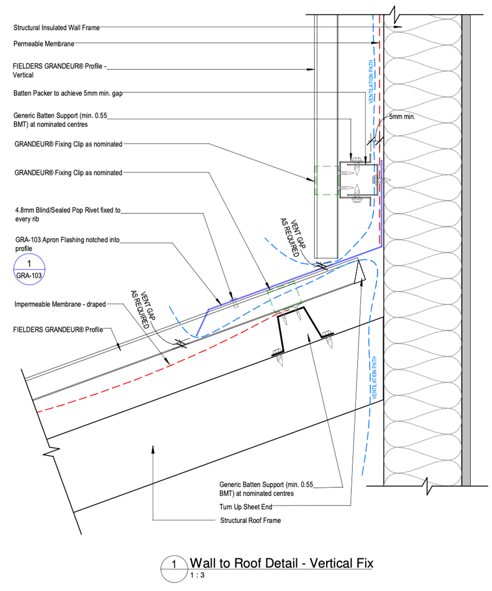
Figure GR ID NC - G12-11 - Vertical Fix Wall to Roof - Unsupported - Side View
Vertical Fix Wall to Roof - Unsupported - End View
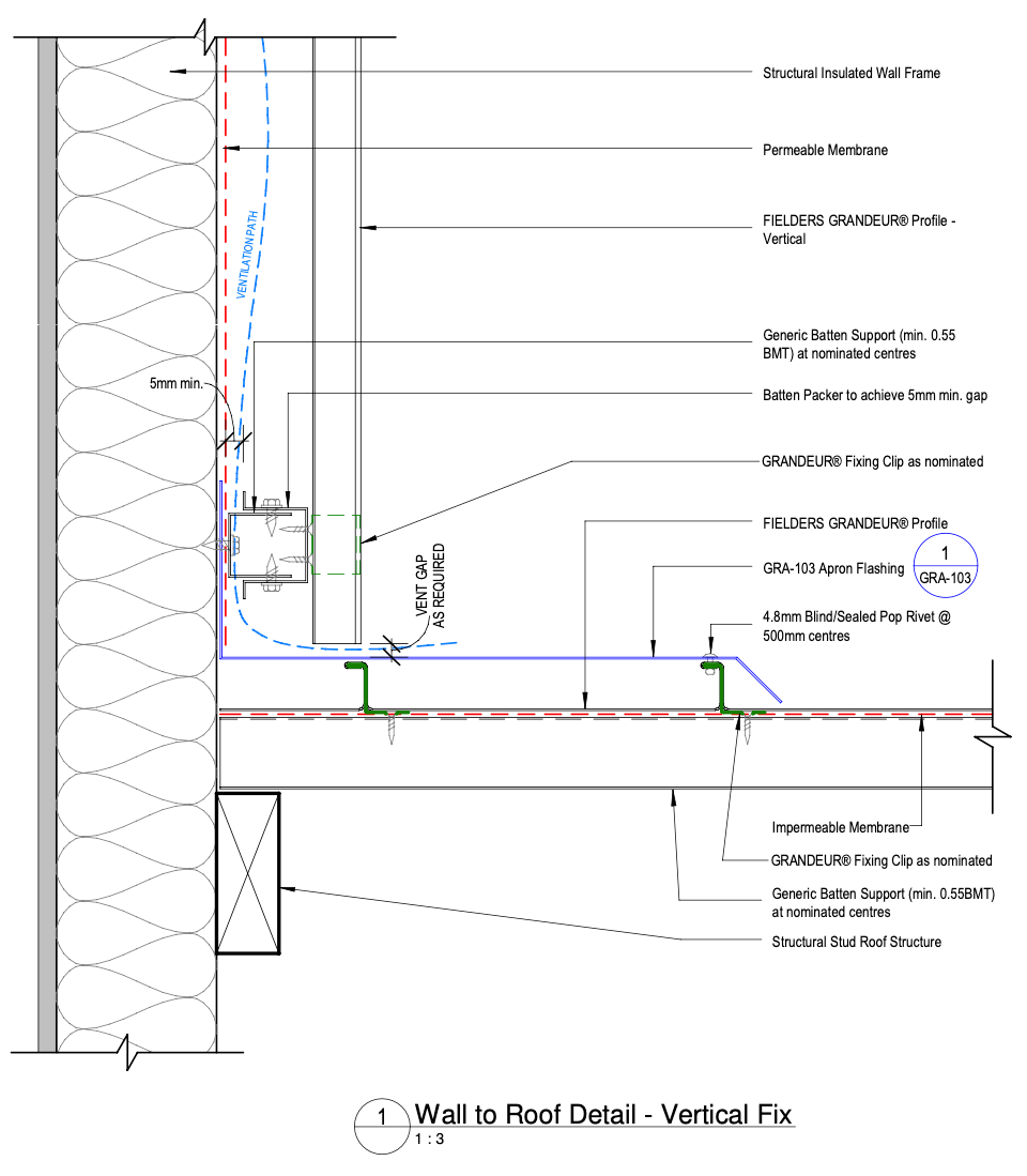
Figure GR ID NC - G12-15 - Vertical Fix Wall to Roof - Unsupported - End View
Typical Wall Cladding Setout - Unsupported - Plan View - Vertical Fix
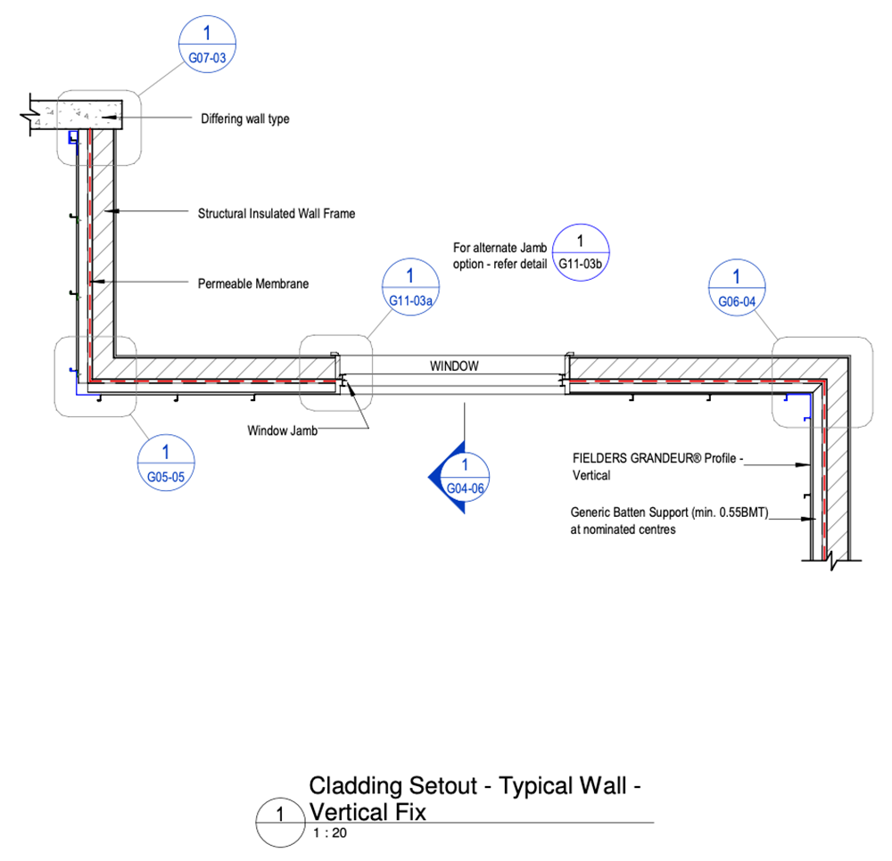
Figure GR ID NC - G04-05 - Typical Wall Cladding Setout - Unsupported - Plan View - Vertical Fix
Typical Wall Cladding Setout - Unsupported - Sectional View - Vertical Fix
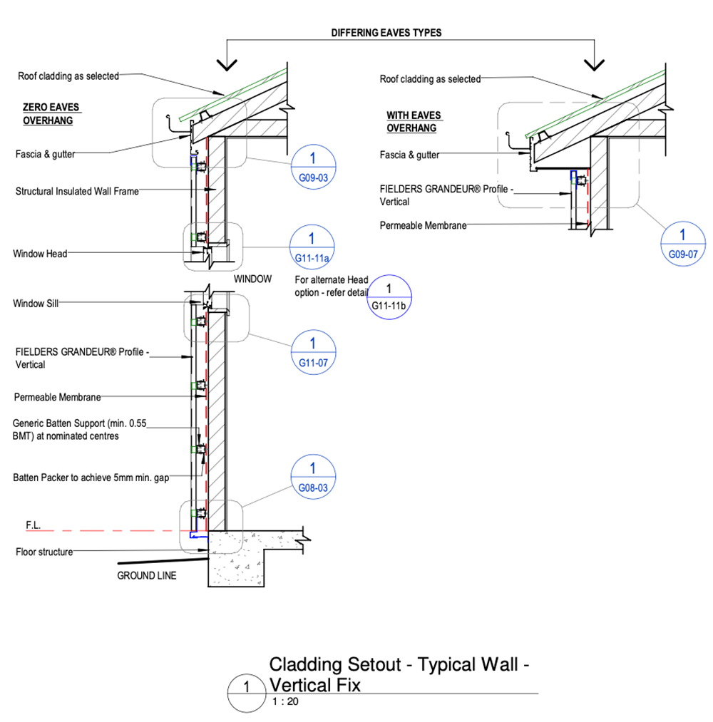
Figure GR ID NC - G04-06 - Typical Wall Cladding Setout - Unsupported - Sectional View - Vertical Fix
External Corner Detail - Unsupported - Vertical Fix F-M
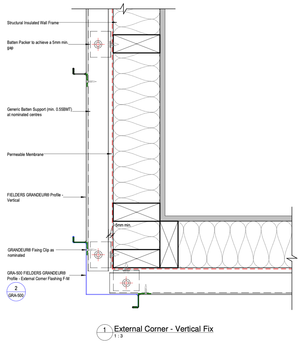
Figure GR ID NC - G05-05 - External Corner Detail - Unsupported - Vertical Fix F-M
Internal Corner Detail- Unsupported Panel - Vertical Fix F-F
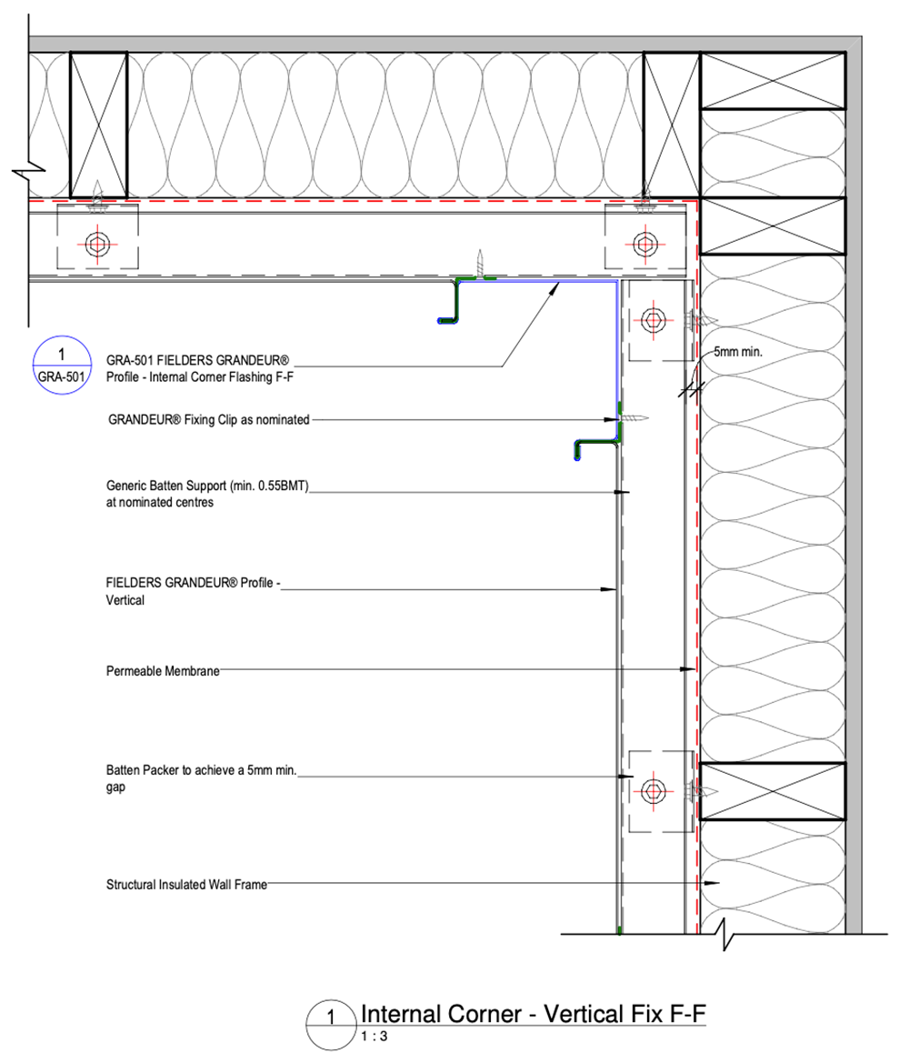
Figure GR ID NC - G06-04 - Internal Corner Detail- Unsupported Panel - Vertical Fix F-F
Wall Closure Detail - Unsupported Panel - Vertical Fix
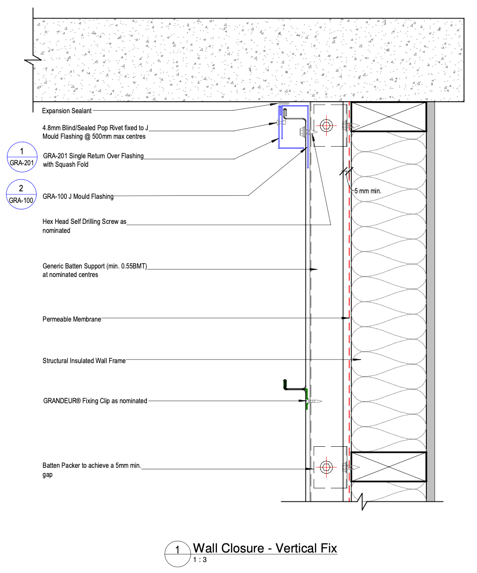
Figure GR ID NC - G07-03 - Wall Closure Detail - Unsupported Panel - Vertical Fix
Wall Base Detail - Unsupported Panel - Vertical Fix
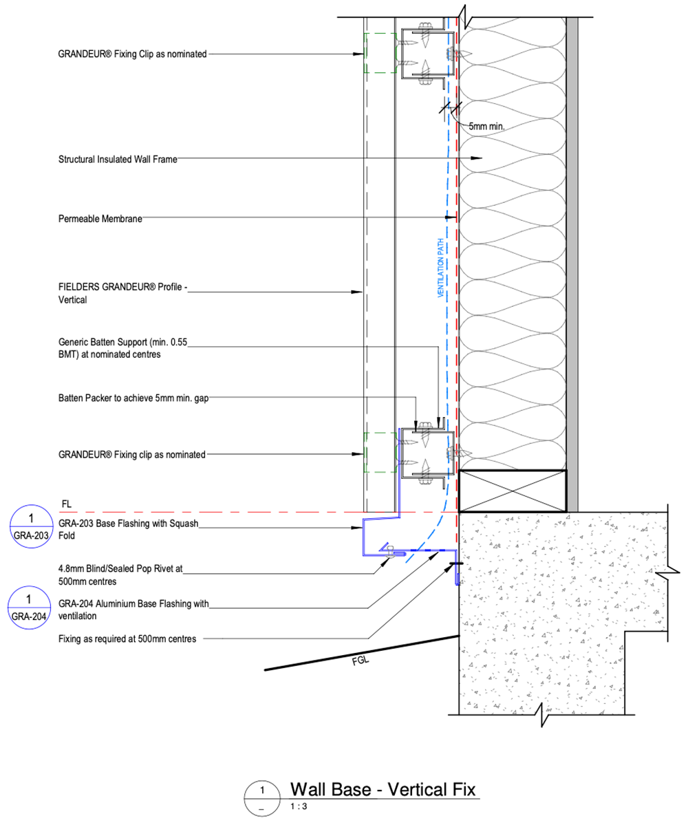
Figure GR ID NC - G08-03 - Wall Base Detail - Unsupported Panel - Vertical Fix
Top of Wall Eave Detail - Zero Overhang - Unsupported - Vertical Fix
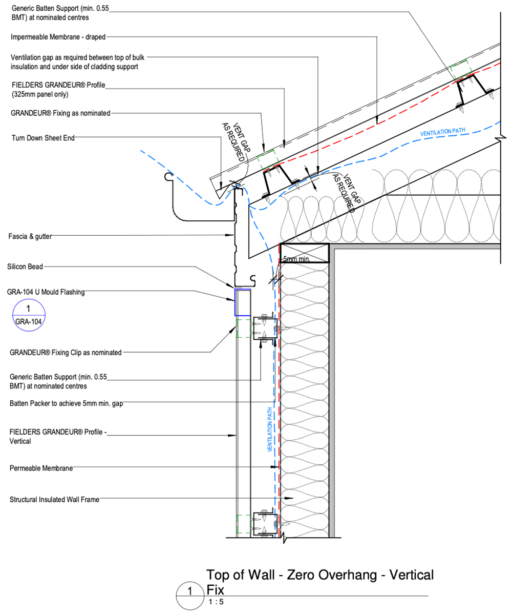
Figure GR ID NC - G09-03 - Top of Wall Eave Detail - Zero Overhang - Unsupported - Vertical Fix
Top of Wall Eave Detail - Overhang - Unsupported - Vertical Fix
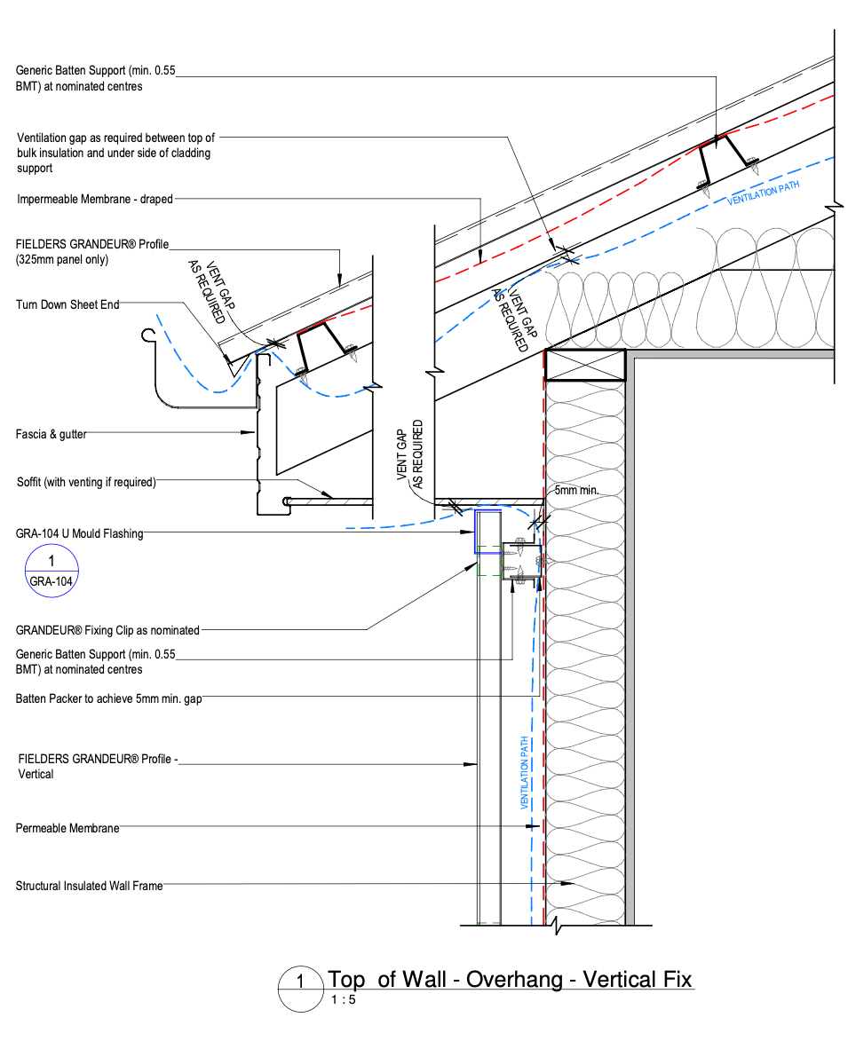
Figure GR ID NC - G09-07 - Top of Wall Eave Detail - Overhang - Unsupported - Vertical Fix
Window Jamb Detail - Unsupported Panel - Vertical Fix - Option 1
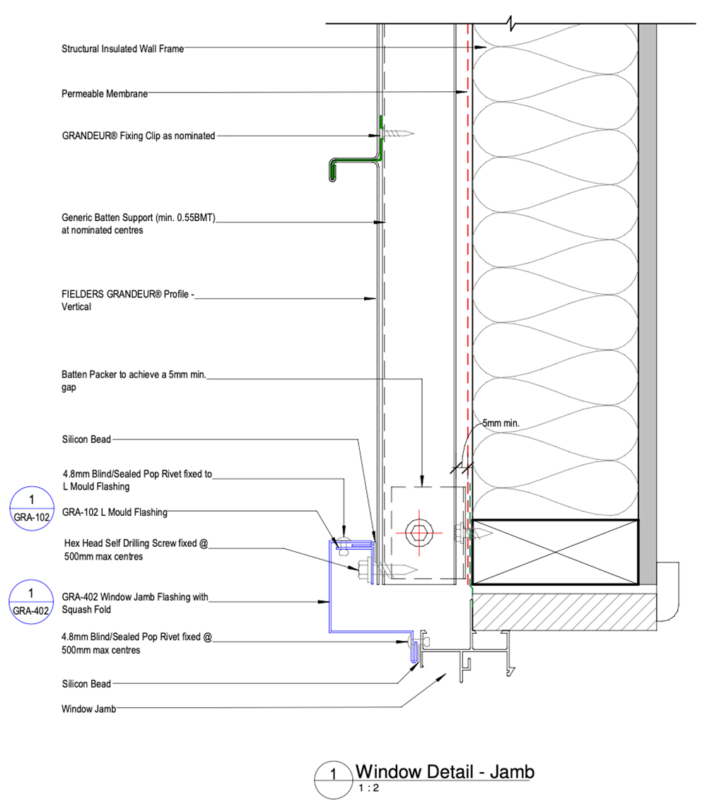
Figure GR ID NC - G11-03a - Window Jamb Detail - Unsupported Panel - Vertical Fix - Option 1
Window Jamb Detail - Unsupported Panel - Vertical Fix - Option 2
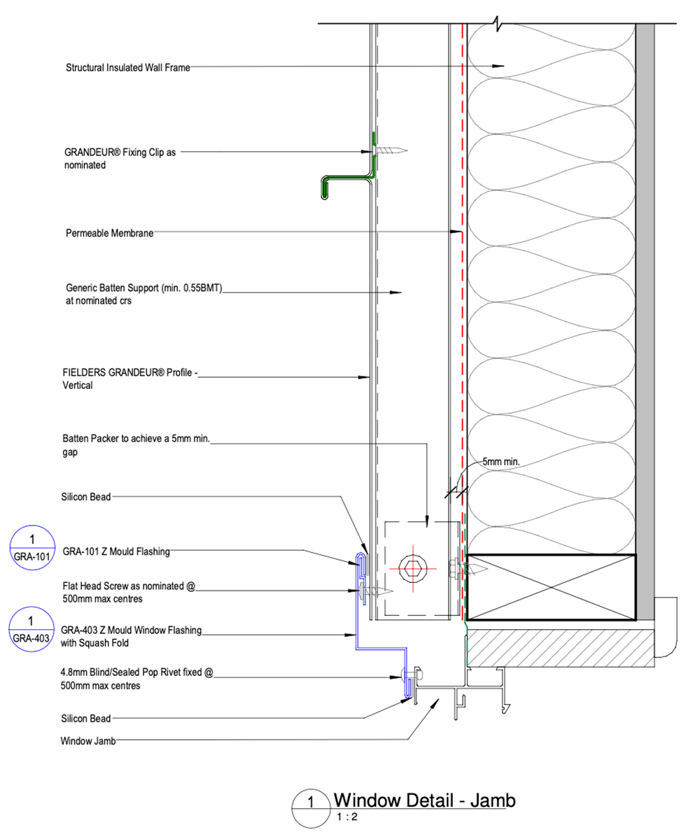
Figure GR ID NC - G11-03b - Window Jamb Detail - Unsupported Panel - Vertical Fix - Option 2
Window Sill Detail - Unsupported Panel - Vertical Fix
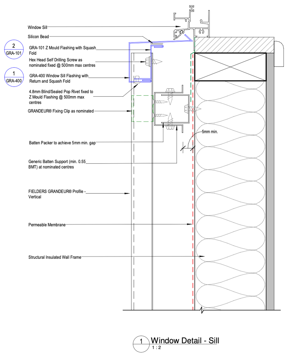
Figure GR ID NC - G11-07 - Window Sill Detail - Unsupported Panel - Vertical Fix
Window Head Detail - Unsupported Panel - Vertical Fix - Option 1
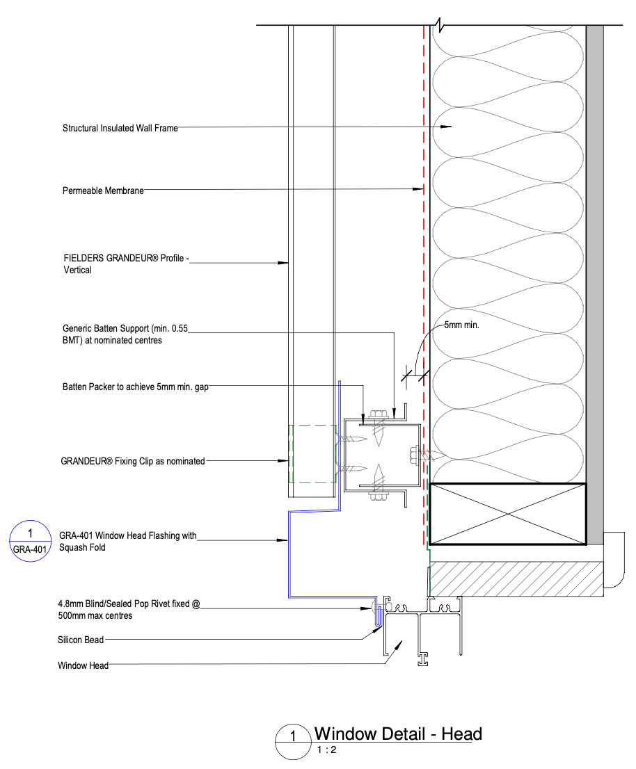
Figure GR ID NC - G11-01a - Window Head Detail - Unsupported Panel - Vertical Fix - Option 1
Window Head Detail - Unsupported Panel - Vertical Fix - Option 2
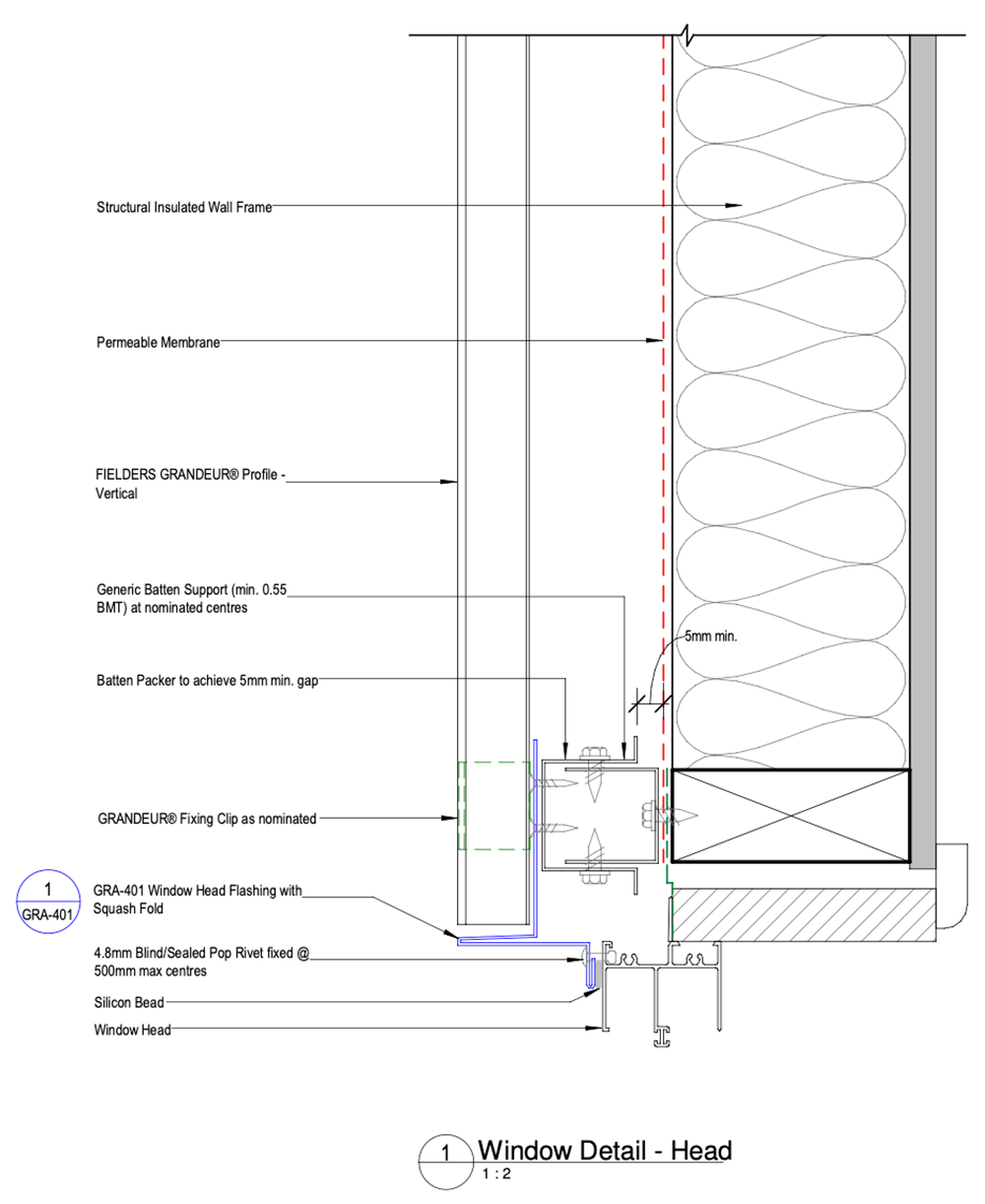
Figure GR ID NC - G11-01b - Window Head Detail - Unsupported Panel - Vertical Fix - Option 2
Foam Infills
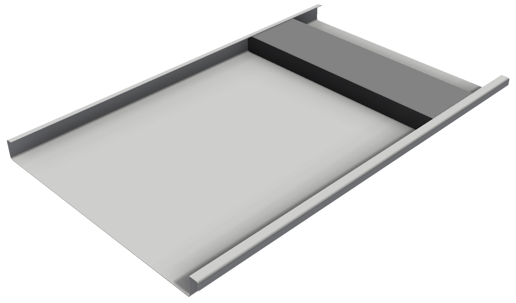
Figure GR ID NC 013
Note:
80mm wide x 30mm high x 1.2m long closed cell foam infills maybe cut to size on site and installed under ridge and hip flashings should be considered for additional weather proofing in high wind areas