
Rainfall Capacity
For further information, please refer to sections “Rainfall Intensity” and “Water Carrying Capacity and Rainwater Run-Off”.
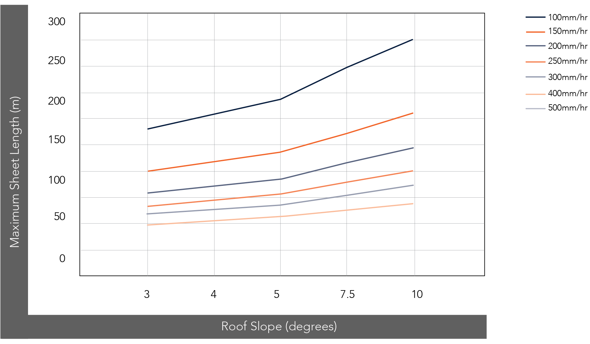
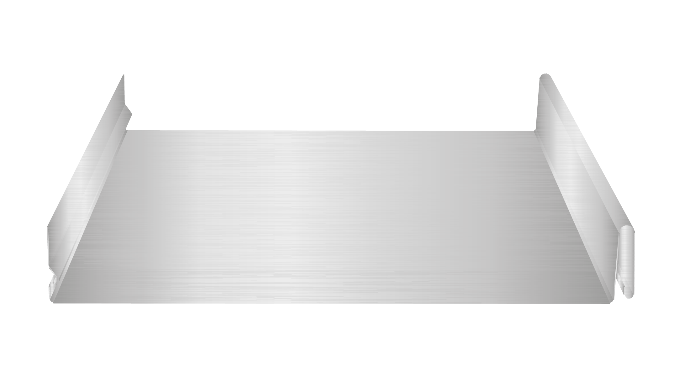
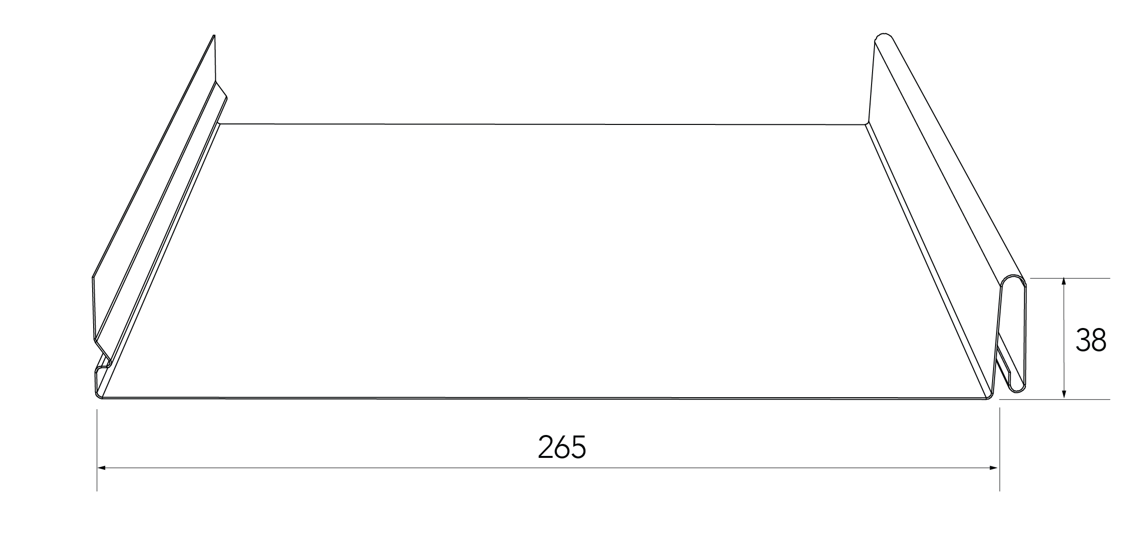
Figure CD RC NC (265) 001
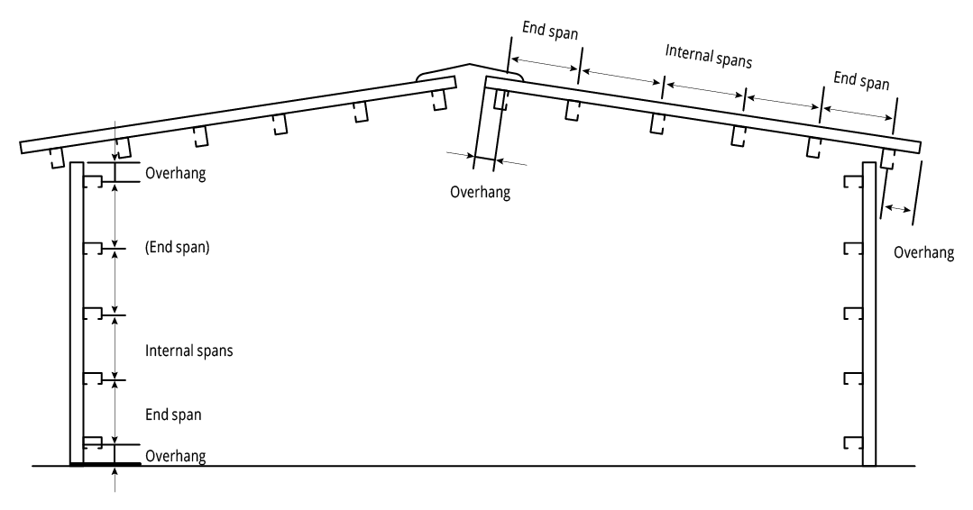
Figure CD NC 001 End Spans, Internal Spans and Overhangs
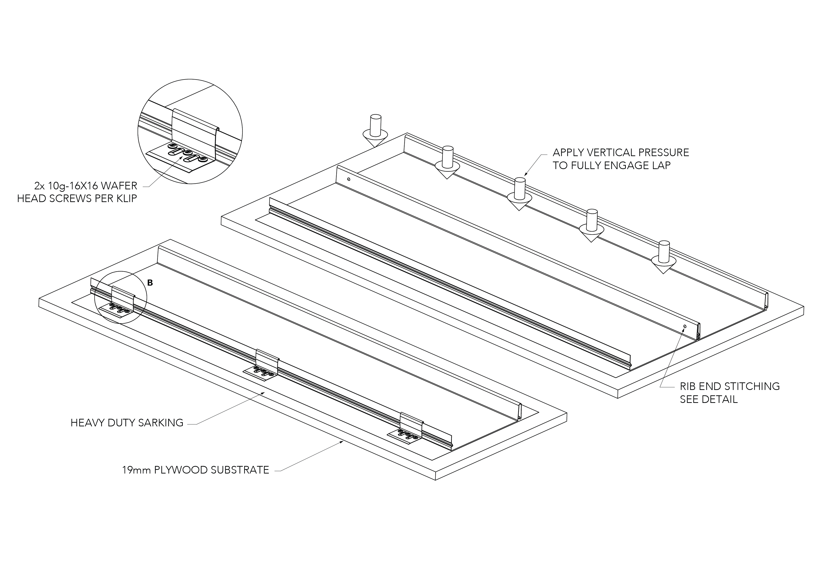
Figure CD ID NC 001 (Plywood)
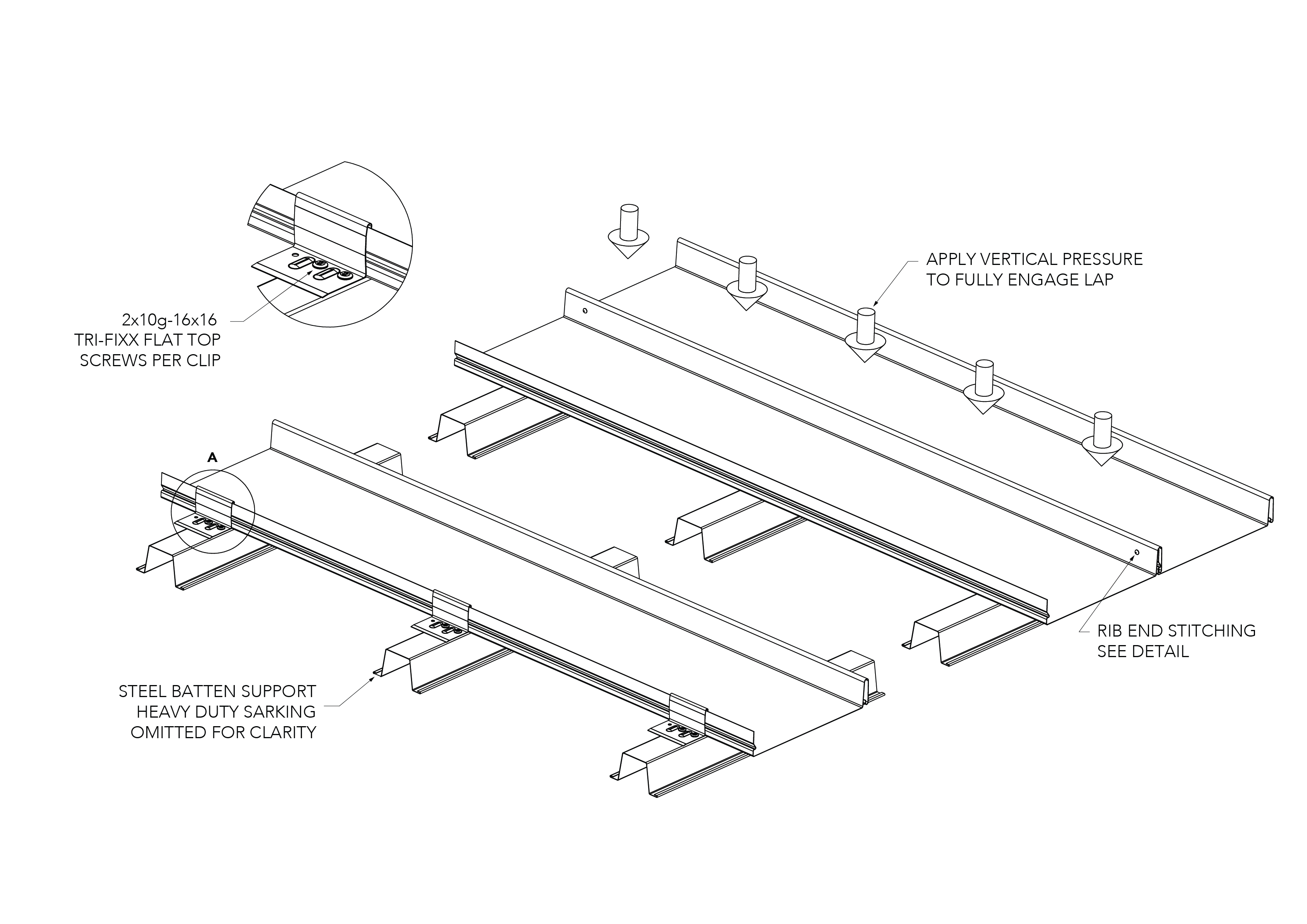
Figure CD ID NC 002 (Steel Batten)
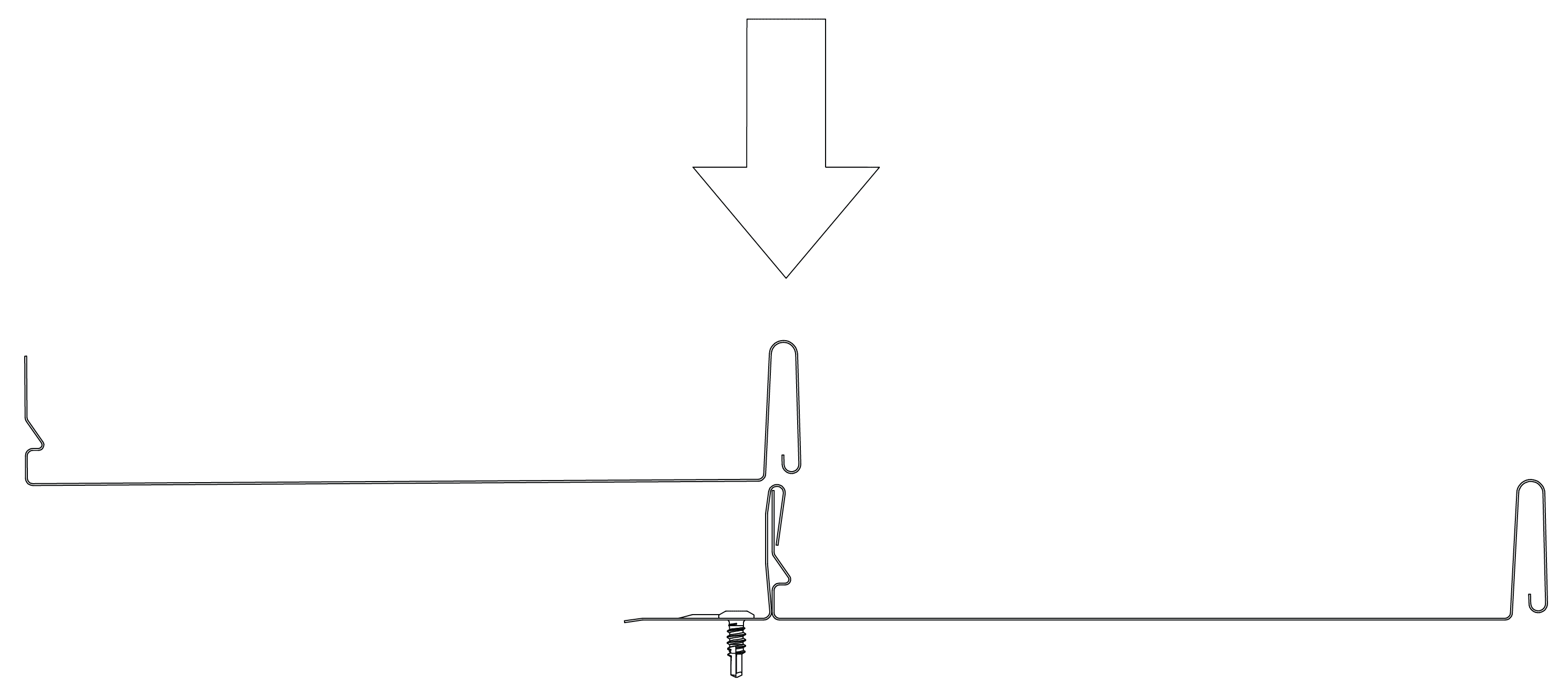
Figure CD ID LE 001
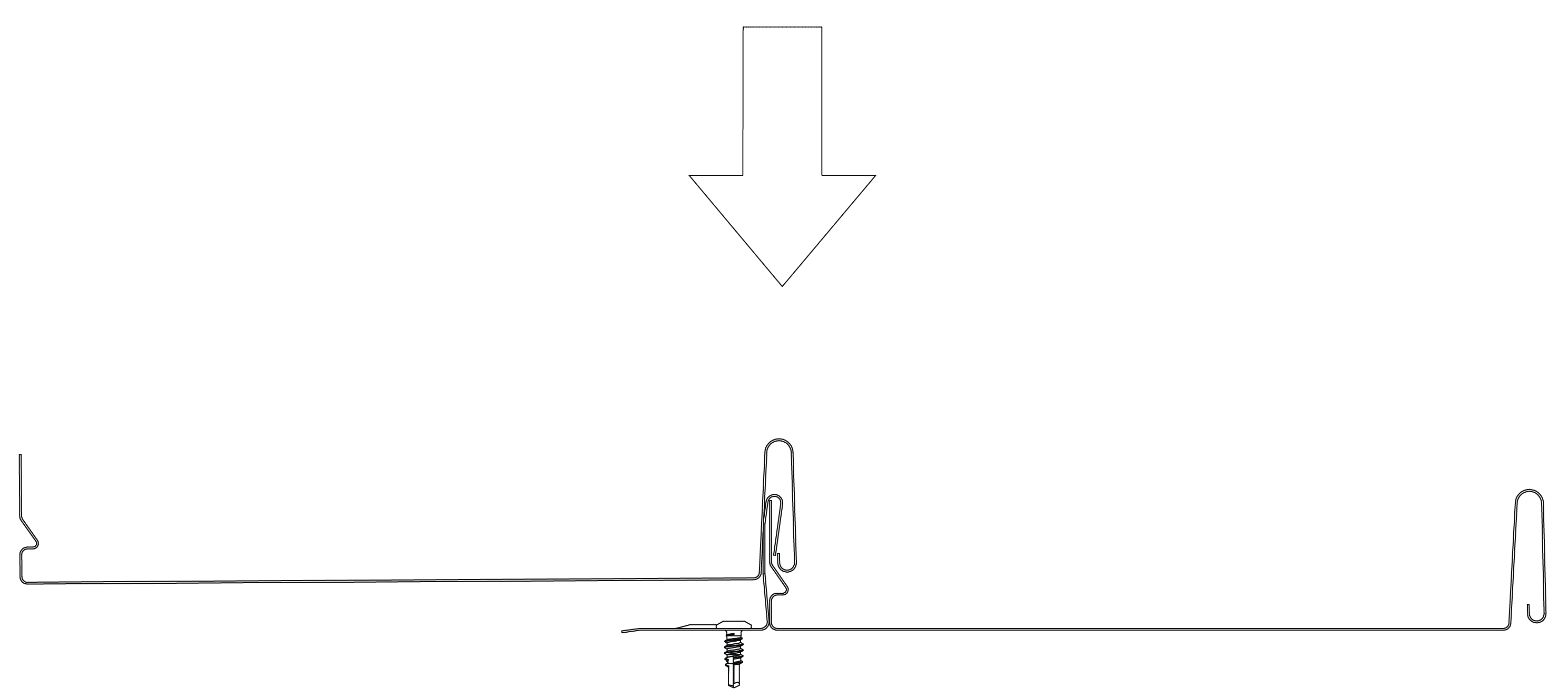
Figure CD ID LE 002

Figure CD ID LE 003
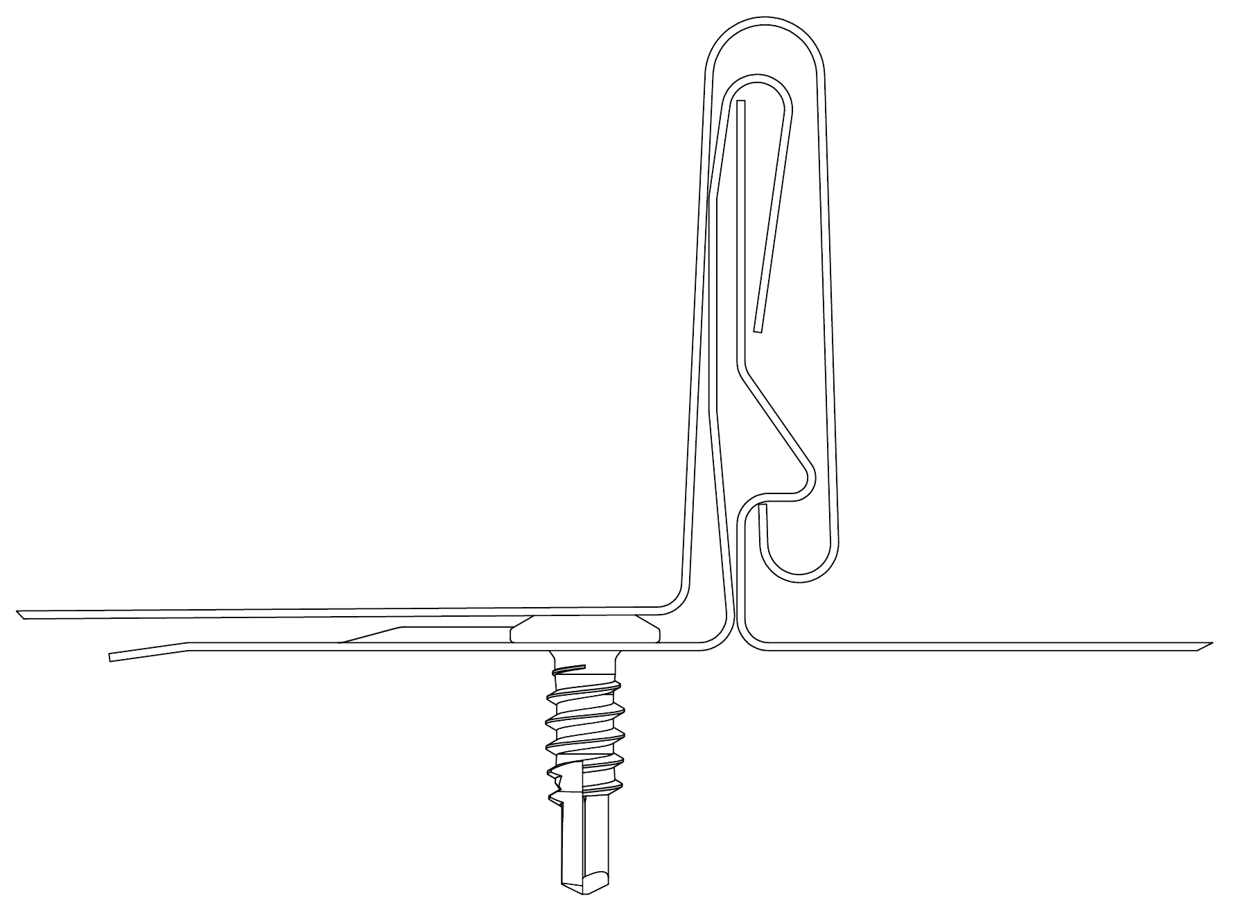
Figure CD ID LE 004
Wall Layout — Vertical
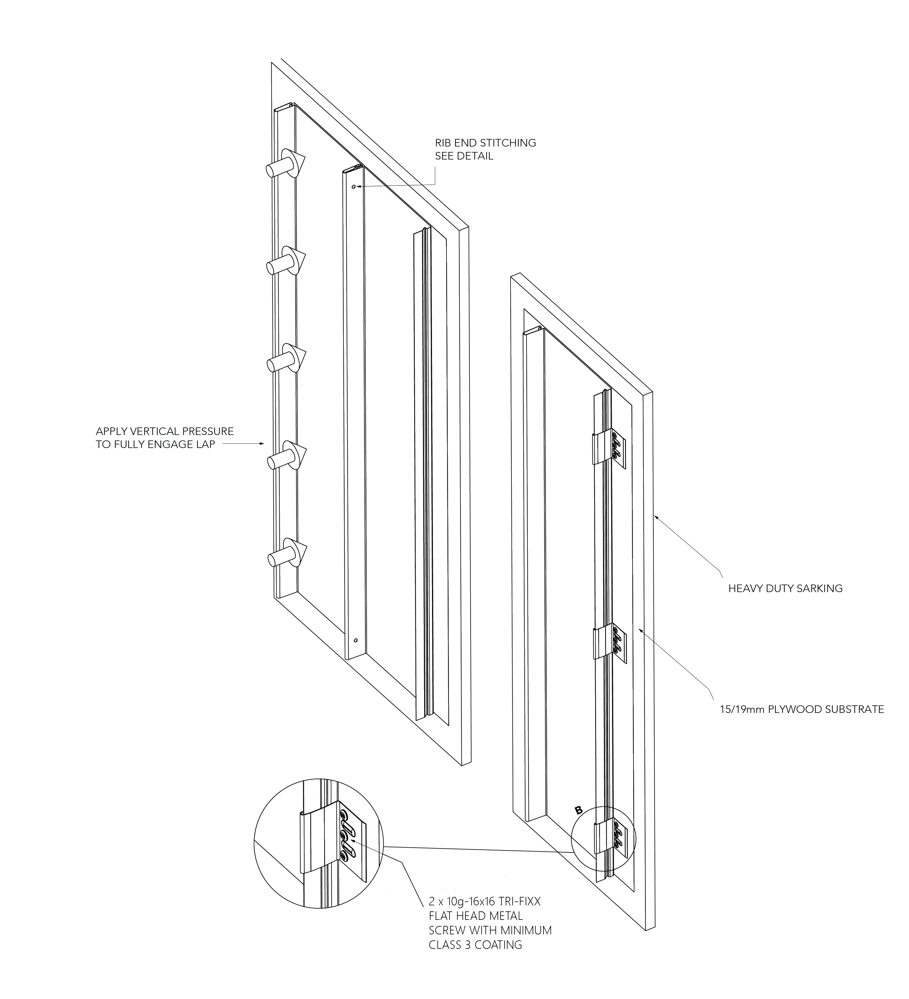
Figure CD ID NC 010
Notes:
*For walling configurations plywood is optional. CADENCE® can be fixed directly to the framing system provided fixings do not exceed those specified in Table PR RS NC 001 (closer spacings may be required in high wind zones, confirm with Fielders). In areas where impact of the material is possible, plywood is recommended to minimise damage to the profile.
Typical Roof Cladding Setout - Unsupported - Plan View
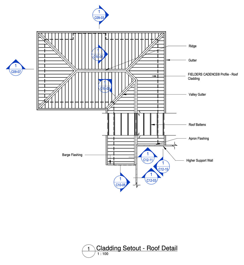
Figure CD ID NC - C04-09 - Typical Roof Cladding Setout - Unsupported - Plan View
Top of Wall Eave Detail - Zero Overhang - Unsupported - Vertical Fix
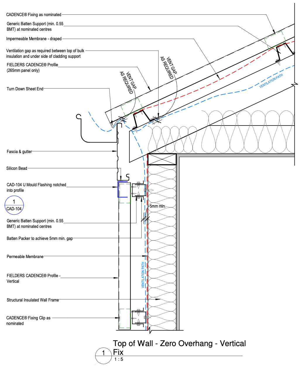
Figure CD ID NC - C09-03 - Top of Wall Eave Detail - Zero Overhang - Unsupported - Vertical Fix
Top of Wall Eave Detail - Overhang - Unsupported - Vertical Fix
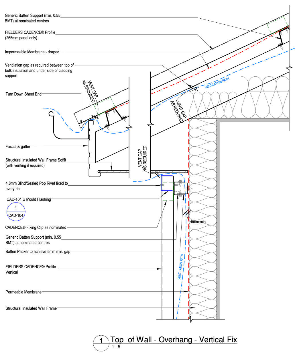
Figure CD ID NC - C09-07 - Top of Wall Eave Detail - Overhang - Unsupported - Vertical Fix
Ridge Detail - Unsupported - Panel
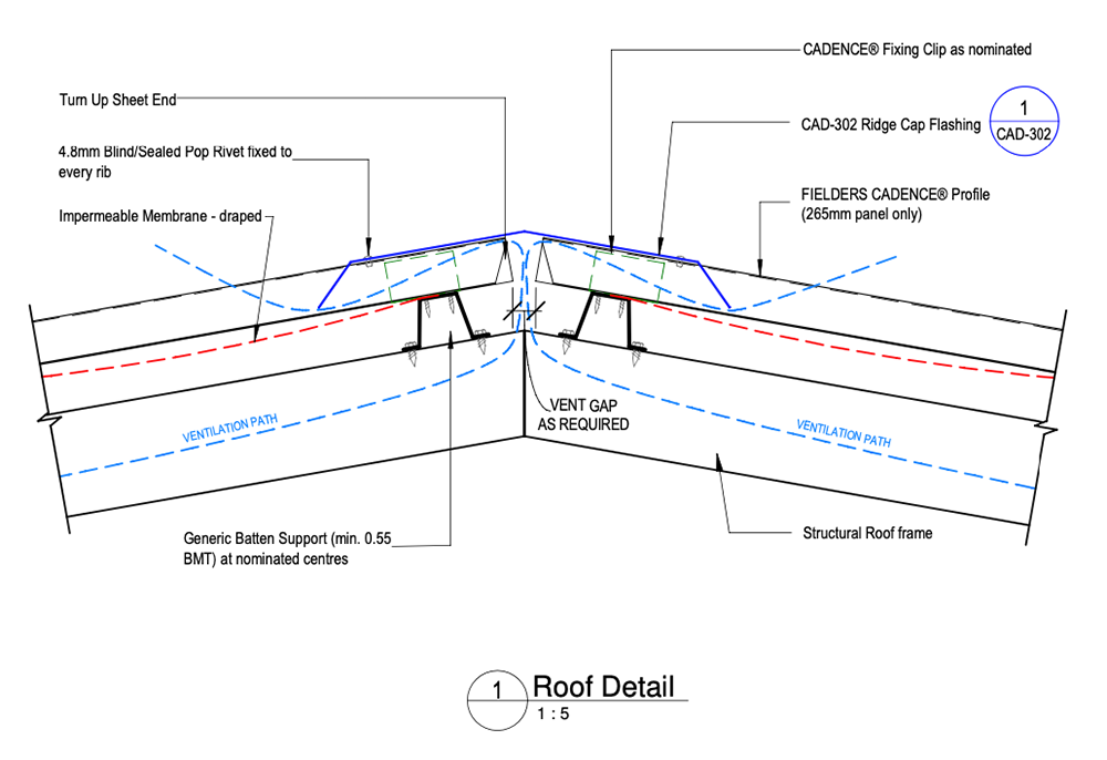
Figure CD ID NC - C10-01 - Ridge Detail - Unsupported - Panel
Valley Detail - Unsupported Fielders Cadence® Panel
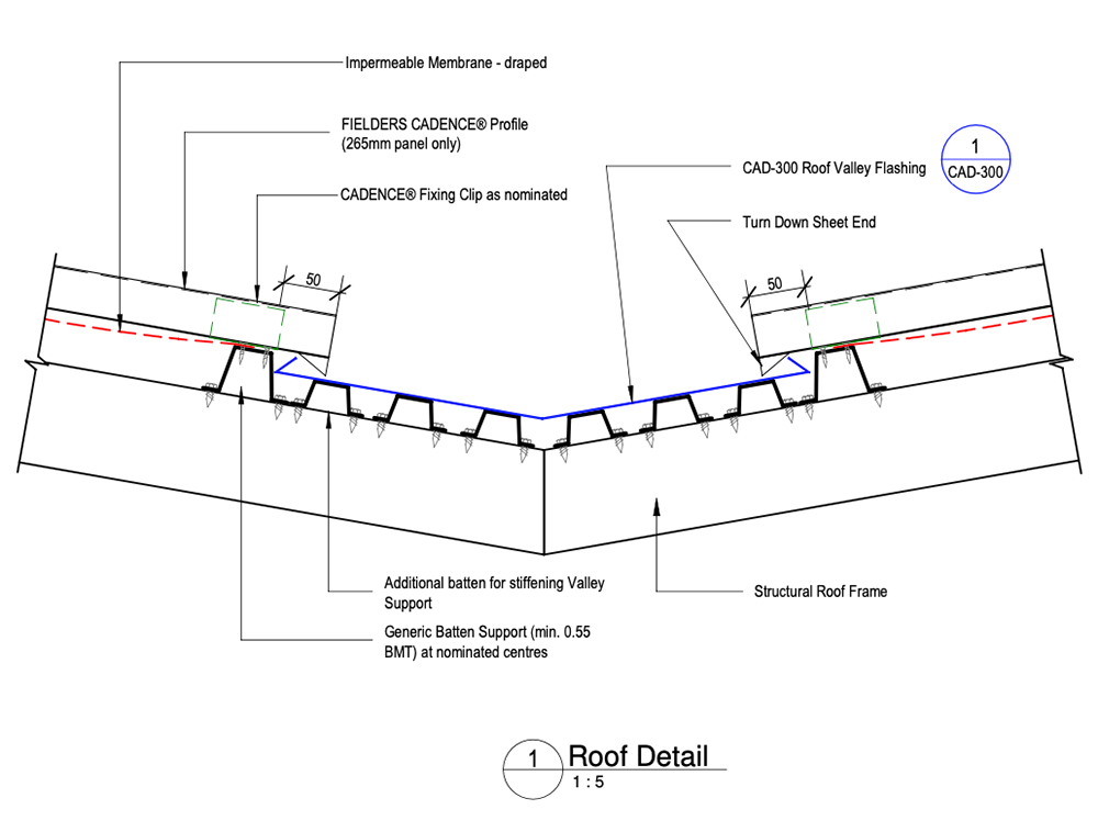
Figure CD ID NC - C10-03 - Valley Detail - Unsupported Fielders Cadence® Panel
Gable Detail - Unsupported Fielders Cadence® Roof and Wall - Vertical Fix
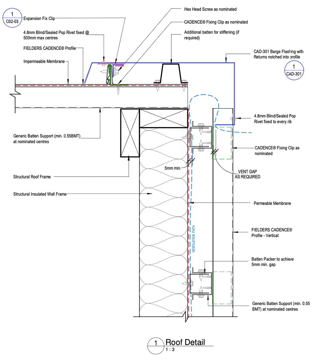
Figure CD ID NC - C10-05 - Gable Detail - Unsupported Fielders Cadence® Roof and Wall - Vertical Fix
Parapet Wall Detail - Unsupported Fielders Cadence® Panel - Vertical Fix
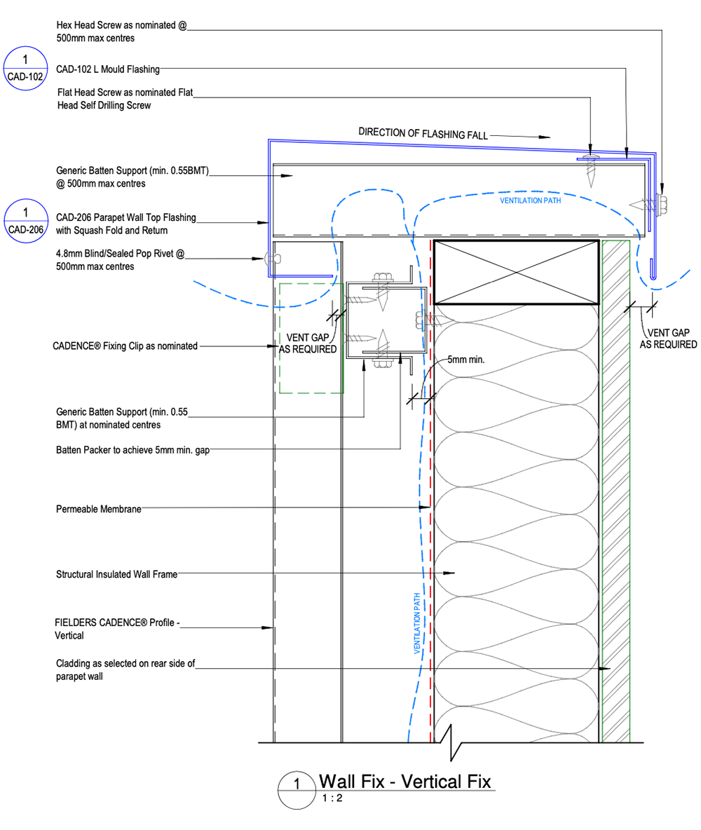
Figure CD ID NC - C12-03 - Parapet Wall Detail - Unsupported Fielders Cadence® Panel - Vertical Fix
Fielders Cadence® Vertical Fix Wall to Fielders Cadence® Roof - Unsupported - Side View
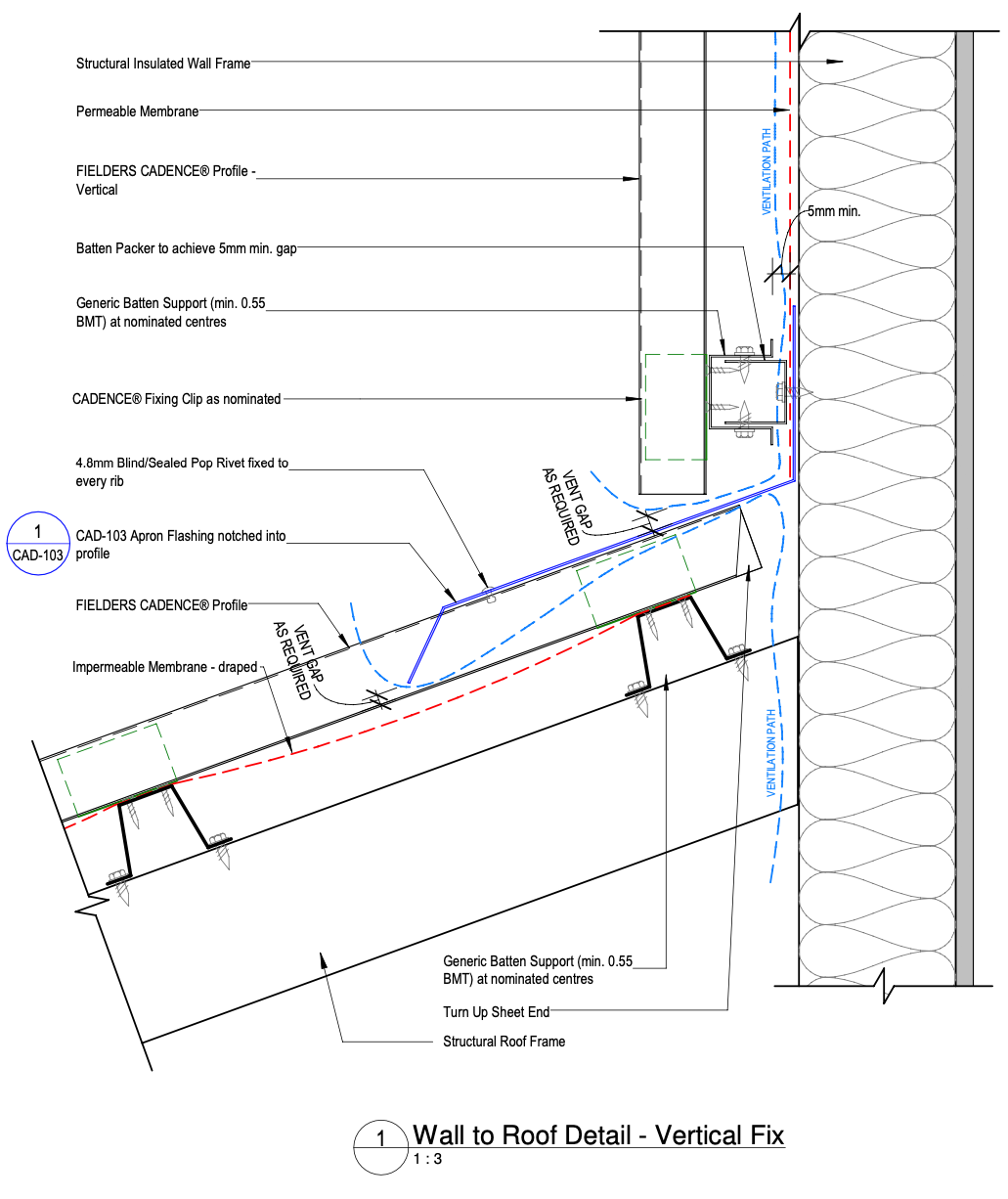
Figure CD ID NC - C12-11 - Fielders Cadence® Vertical Fix Wall to Fielders Cadence® Roof - Unsupported - Side View
Fielders Cadence® Vertical Fix Wall to Fielders Cadence® Roof - Unsupported - End view
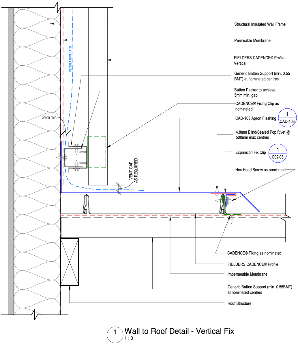
Figure CD ID NC - C12-15 - Fielders Cadence® Vertical Fix Wall to Fielders Cadence® Roof - Unsupported - End view
Typical Wall Cladding Setout - Unsupported Fielders Cadence® Plan View - Vertical Fix
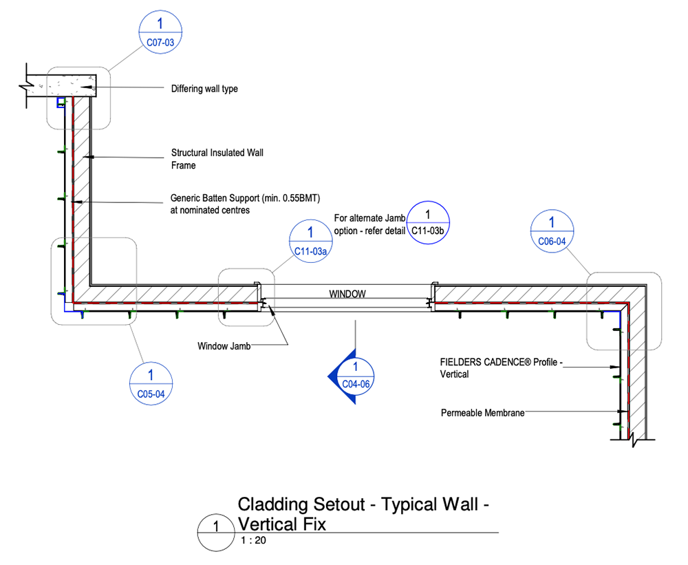
Figure CD ID NC - C04-05 - Typical Wall Cladding Setout - Unsupported Fielders Cadence® Plan View - Vertical Fix
Typical Wall Cladding Setout - Unsupported Fielders Cadence® Sectional View - Vertical Fix
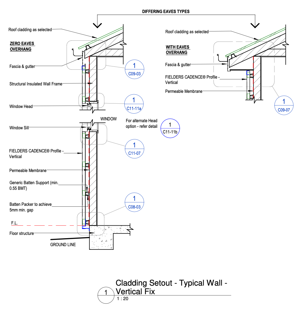
Figure CD ID NC - C04-06 - Typical Wall Cladding Setout - Unsupported Fielders Cadence® Sectional View - Vertical Fix
External Corner Detail - Unsupported Fielders Cadence® Panel - Vertical Fix - Underlap Underlap
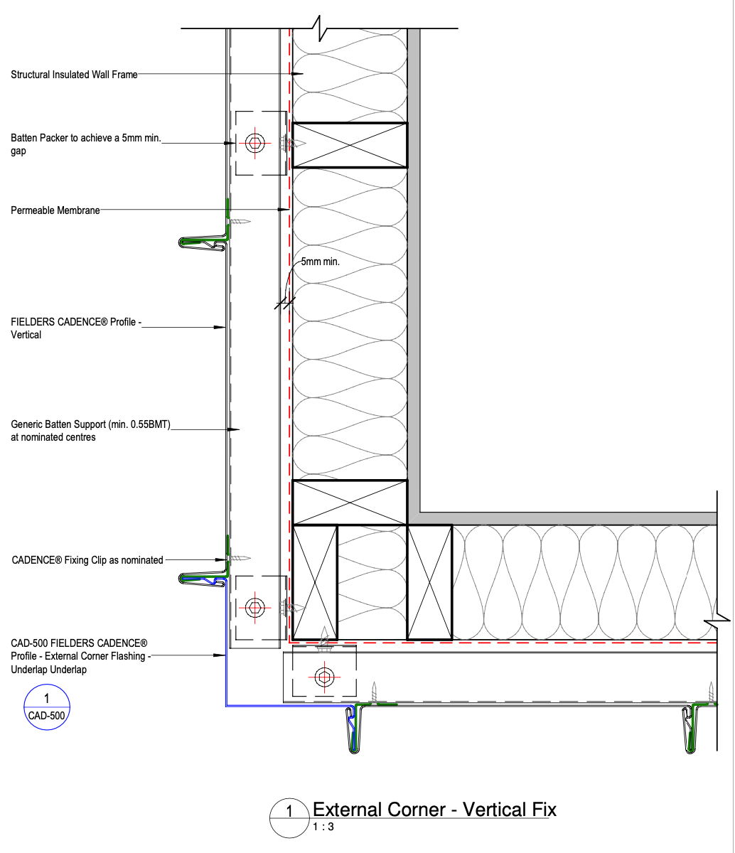
Figure CD ID NC - C05-04 - External Corner Detail - Unsupported Fielders Cadence® Panel - Vertical Fix - Underlap Underlap
Internal Corner Detail- Unsupported Fielders Cadence® Panel - Vertical Fix - Underlap Underlap
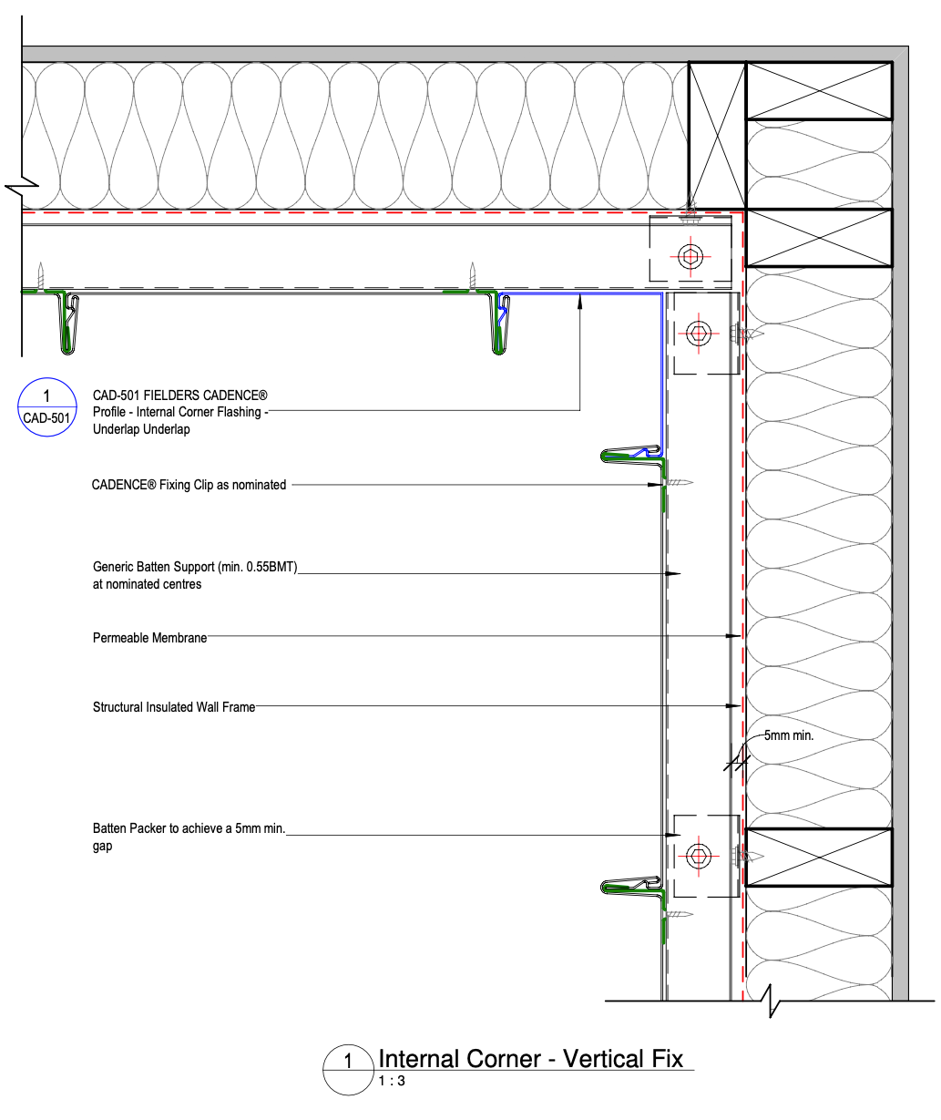
Figure CD ID NC - C06-04 - Internal Corner Detail- Unsupported Fielders Cadence® Panel - Vertical Fix - Underlap Underlap
Wall Closure Detail - Unsupported Fielders Cadence® Panel - Vertical Fix
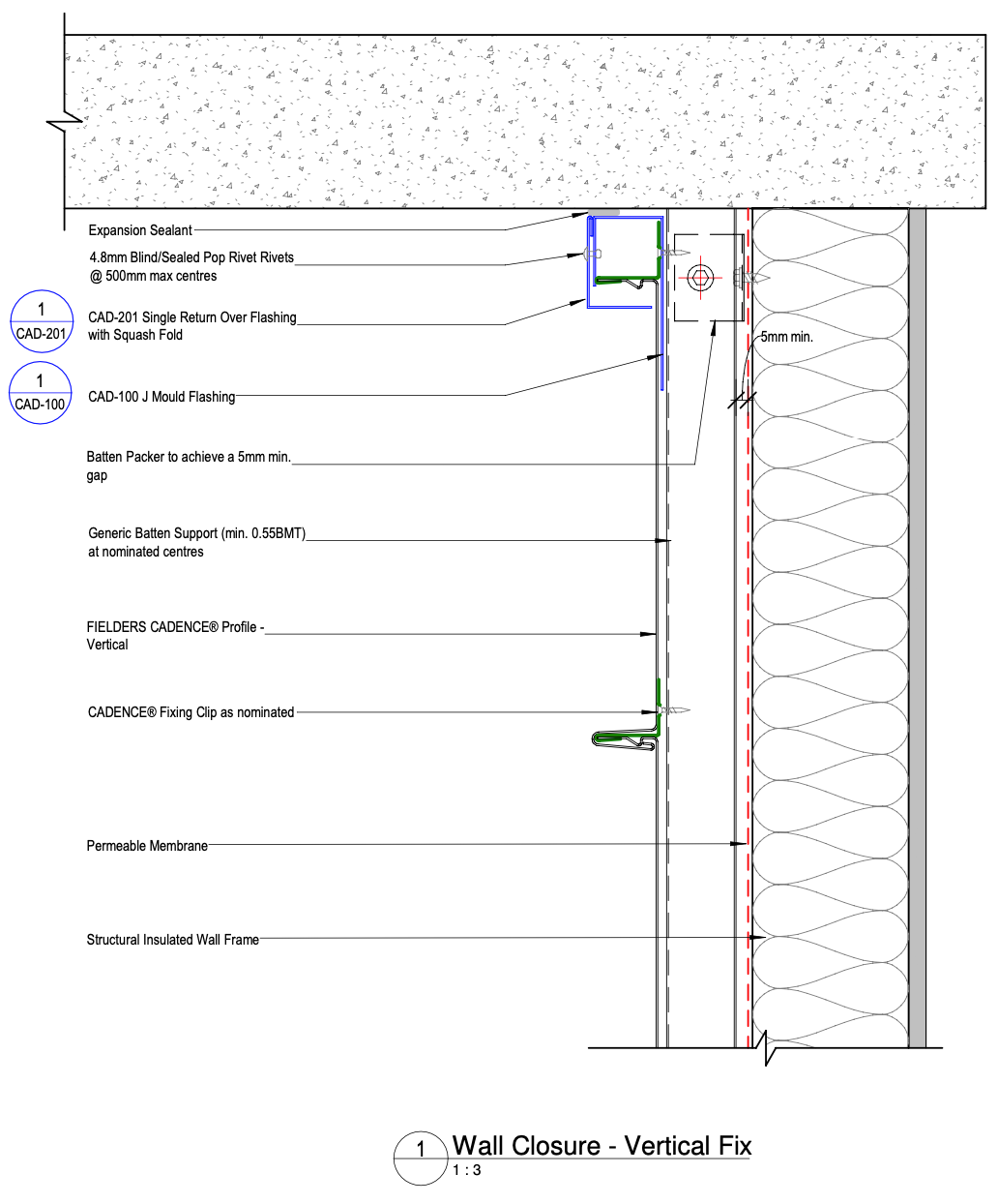
Figure CD ID NC - C07-03 - Wall Closure Detail - Unsupported Fielders Cadence® Panel - Vertical Fix
Wall Base Detail - Unsupported Fielders Cadence® Panel - Vertical Fix
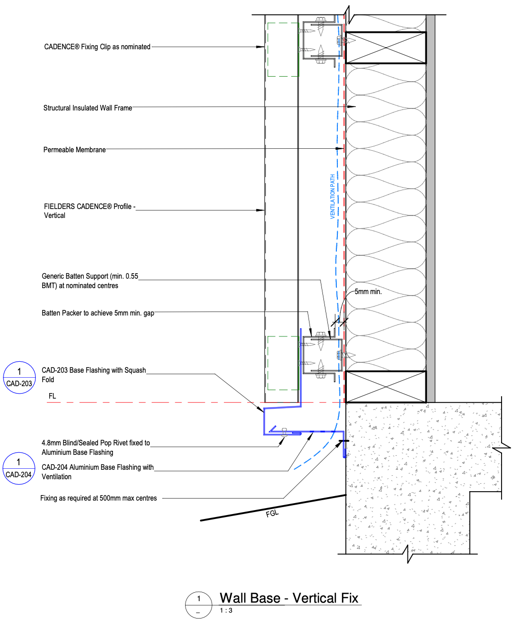
Figure CD ID NC - C08-03 - Wall Base Detail - Unsupported Fielders Cadence® Panel - Vertical Fix
Top of Wall Eave Detail - Zero Overhang - Unsupported Fielders Cadence® - Vertical Fix
Figure CD ID NC - C09-03 - Top of Wall Eave Detail - Zero Overhang - Unsupported Fielders Cadence® - Vertical Fix
Top of Wall Eave Detail - Overhang - Unsupported Fielders Cadence® - Vertical Fix
Figure CD ID NC - C09-07 - Top of Wall Eave Detail - Overhang - Unsupported Fielders Cadence® - Vertical Fix
Window Jamb Detail - Unsupported Fielders Cadence® Panel - Vertical Fix - Option 1
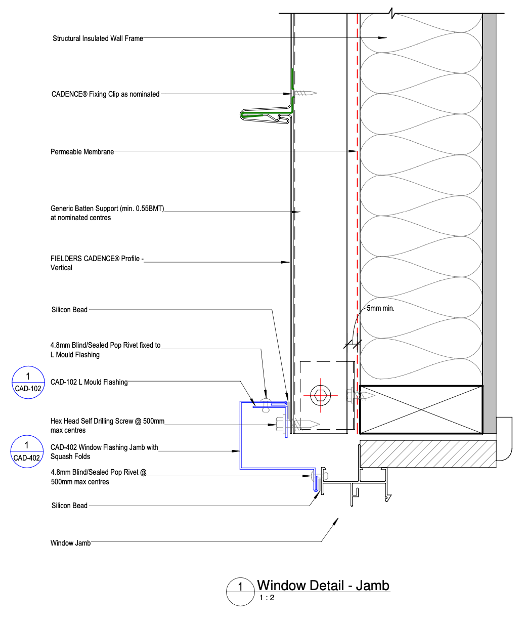
Figure CD ID NC - C11-03a - Window Jamb Detail - Unsupported Fielders Cadence® Panel - Vertical Fix - Option 1
Window Jamb Detail - Unsupported Fielders Cadence® Panel - Vertical Fix - Option 2
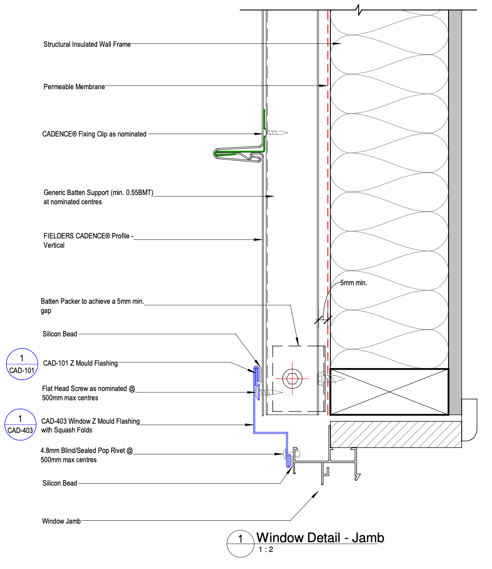
Figure CD ID NC - C11-03b - Window Jamb Detail - Unsupported Fielders Cadence® Panel - Vertical Fix - Option 2
Window Sill Detail - Unsupported Fielders Cadence® Panel - Vertical Fix
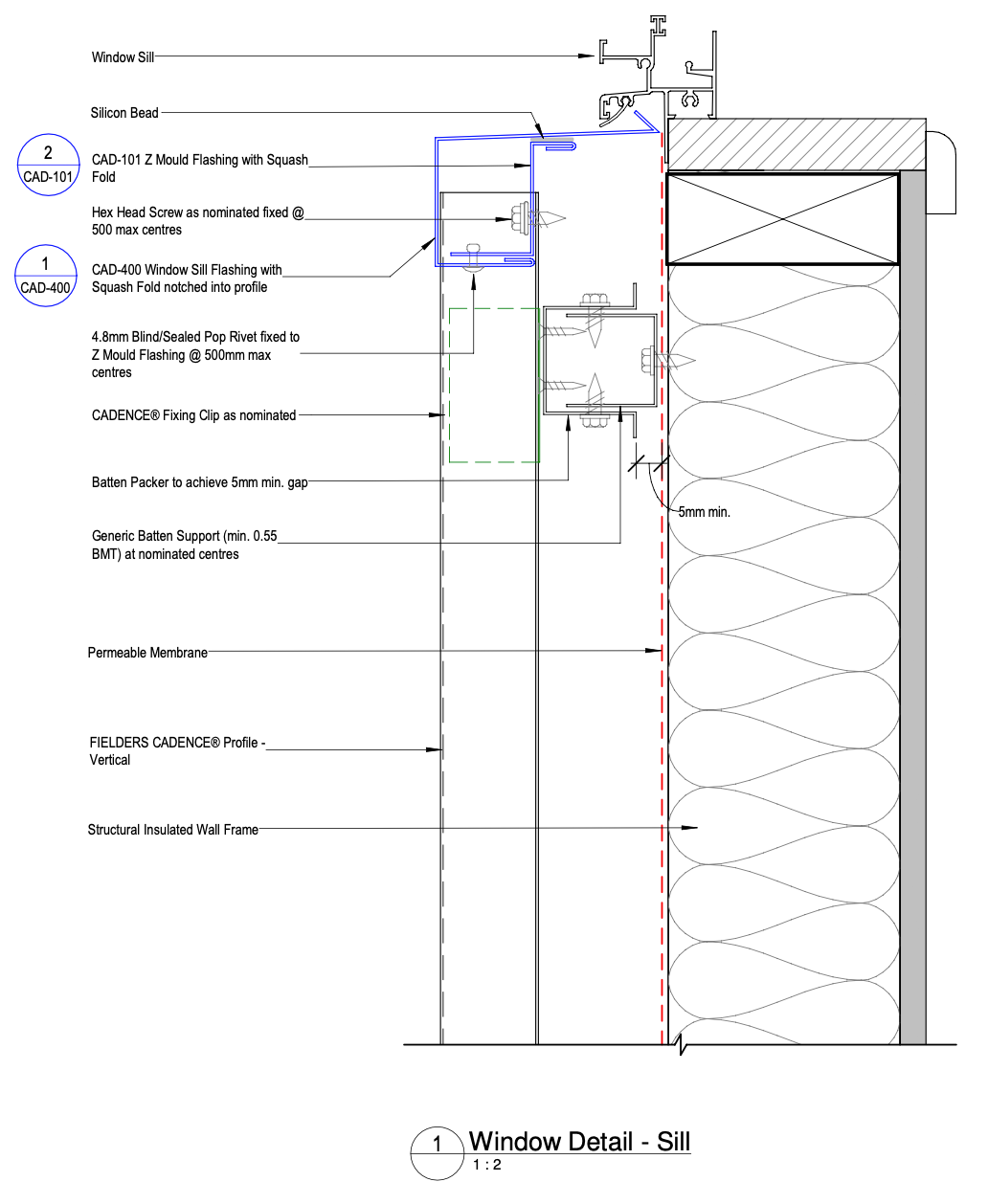
Figure CD ID NC - C11-07 - Window Sill Detail - Unsupported Fielders Cadence® Panel - Vertical Fix
Window Head Detail - Unsupported Fielders Cadence® Panel - Vertical Fix - Option 1
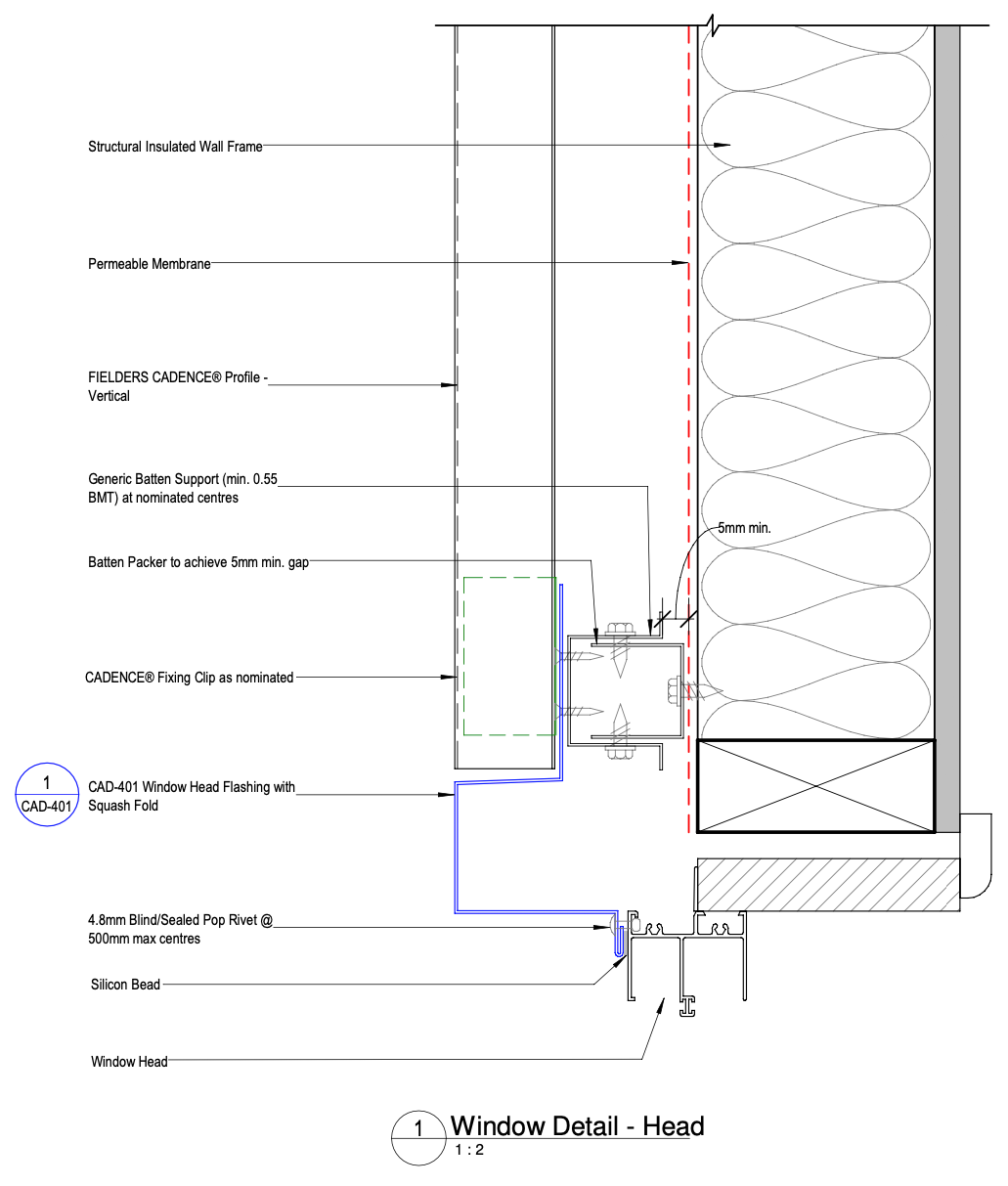
Figure CD ID NC - C11-11a - Window Head Detail - Unsupported Fielders Cadence® Panel - Vertical Fix - Option 1
Window Head Detail - Unsupported Fielders Cadence® Panel - Vertical Fix - Option 2
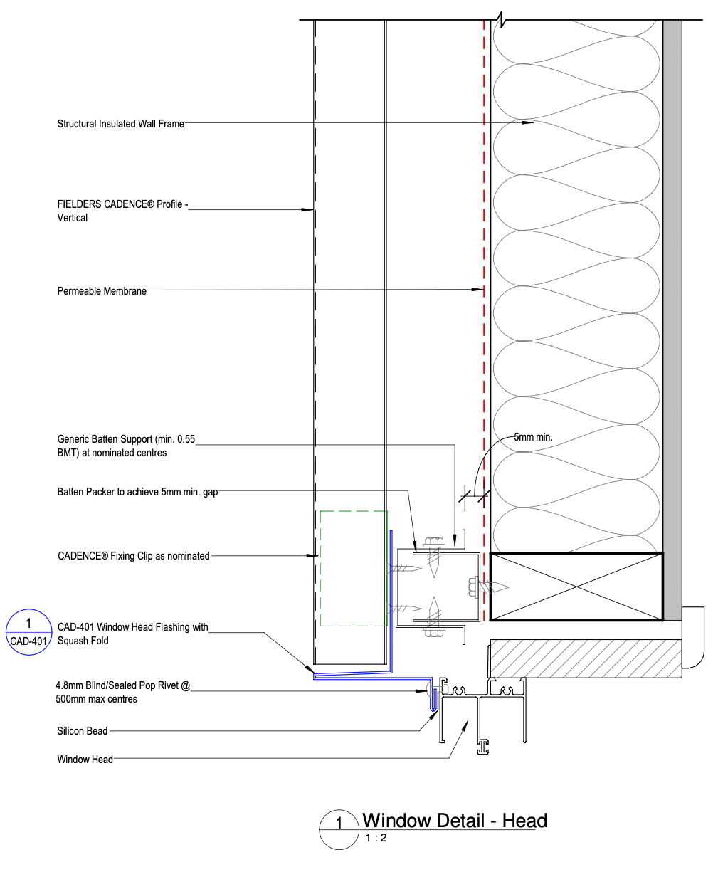
Figure CD ID NC - C11-11b - Window Head Detail - Unsupported Fielders Cadence® Panel - Vertical Fix - Option 2
Fielders Cadence® Vertical Fix Wall to Fielders Cadence® Roof - Unsupported - Side View
Figure CD ID NC - C12-11 - Fielders Cadence® Vertical Fix Wall to Fielders Cadence® Roof - Unsupported - Side View
Fielders Cadence® Vertical Fix Wall to Fielders Cadence® Roof - Unsupported - End view
Figure CD ID NC - C12-15 - Fielders Cadence® Vertical Fix Wall to Fielders Cadence® Roof - Unsupported - End view
Typical Dressed End Capping Without Gutter
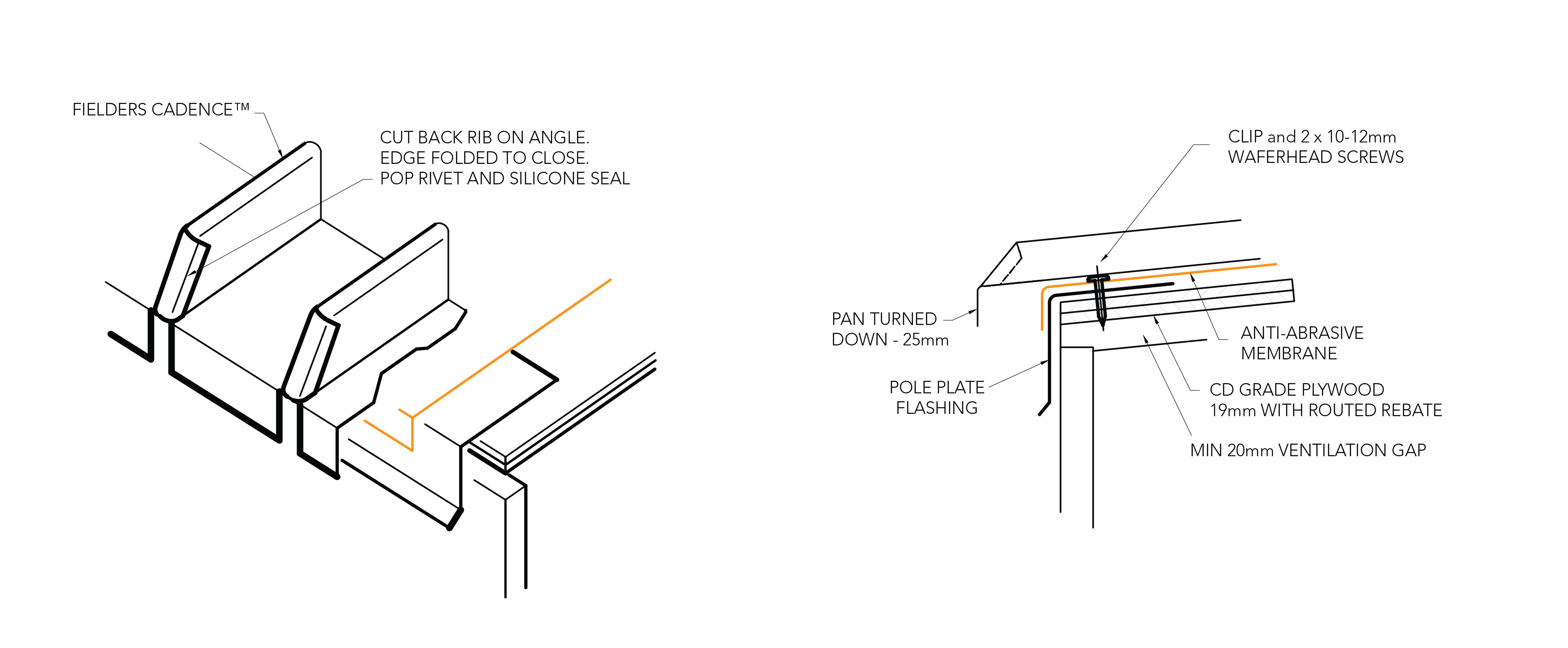
Figure CD ID NC 013
Foam Infills
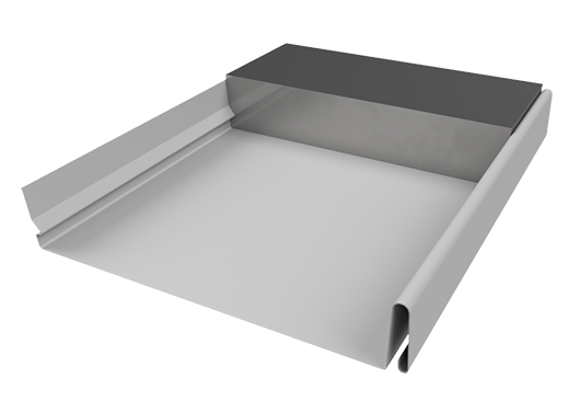
Figure CD ID NC 037
Note:
80mm wide x 40mm high x 1.2m long closed cell foam infills maybe cut to size on site and installed under ridge and hip flashings should be considered for additional weather proofing in high wind areas.
Step 1 - Rib Caps Cut and Folded from Flat Sheet
Development of Cap on Flat Sheet
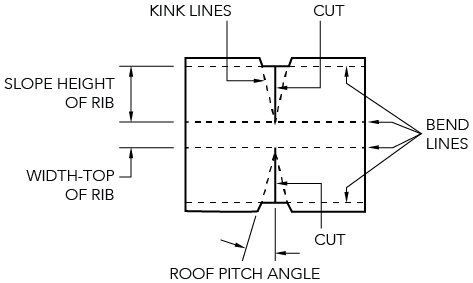
Figure CD ID NC 029
Step 2
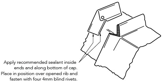
Figure CD ID NC 030
Step 3
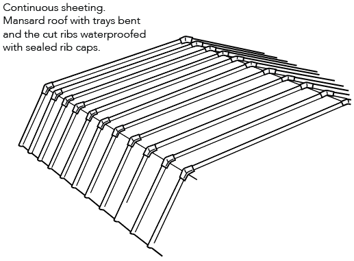
Figure CD ID NC 031
Step 1
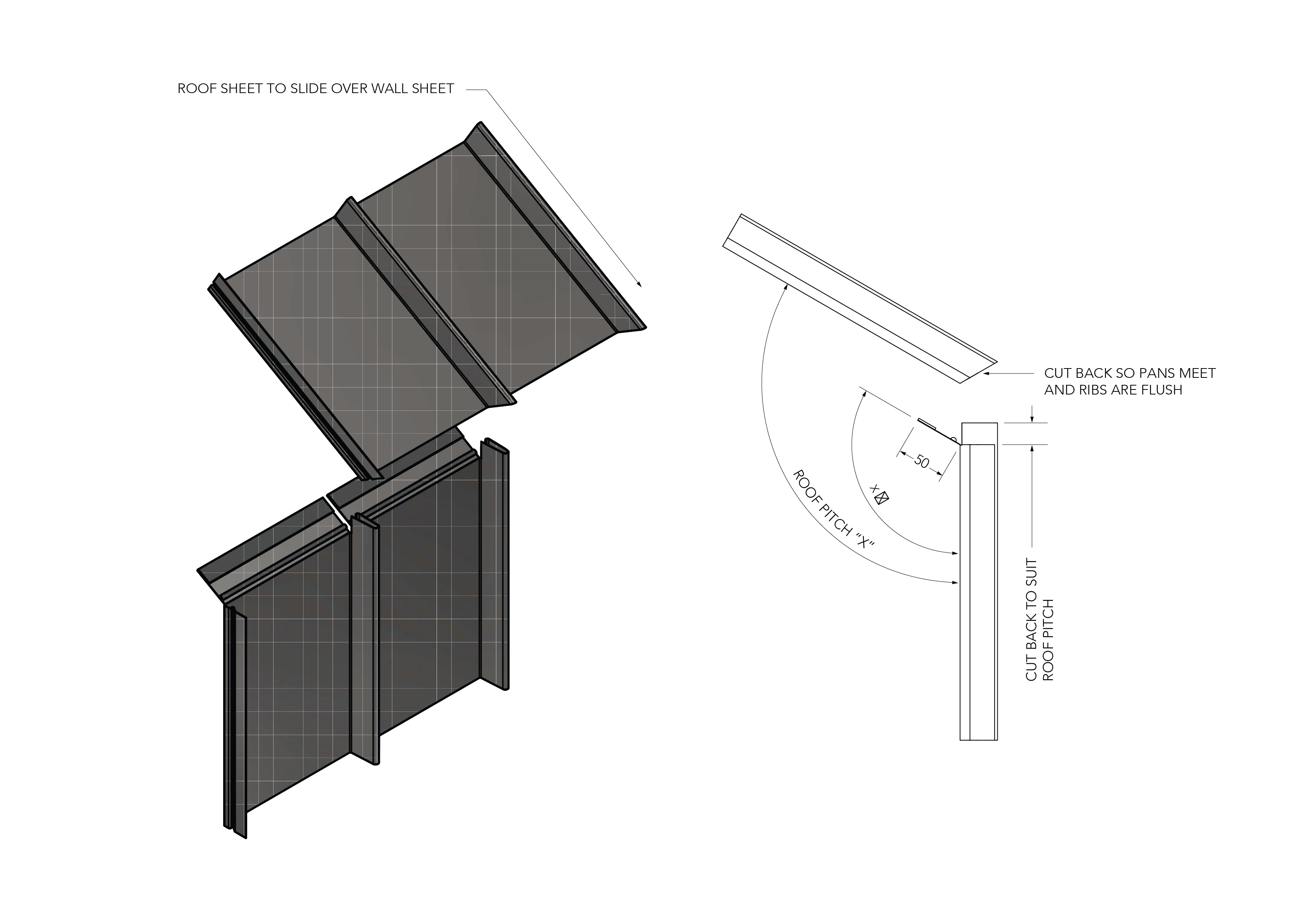
Figure CD ID NC 032
Step 2

Figure CD ID NC 033
Step 3
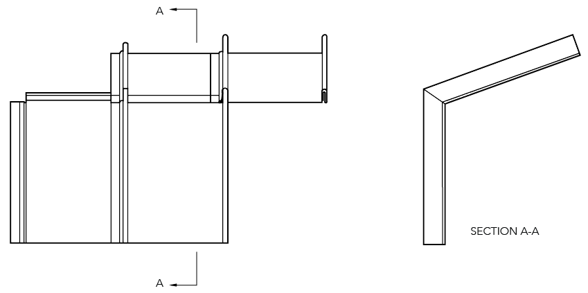
Figure CD ID NC 034
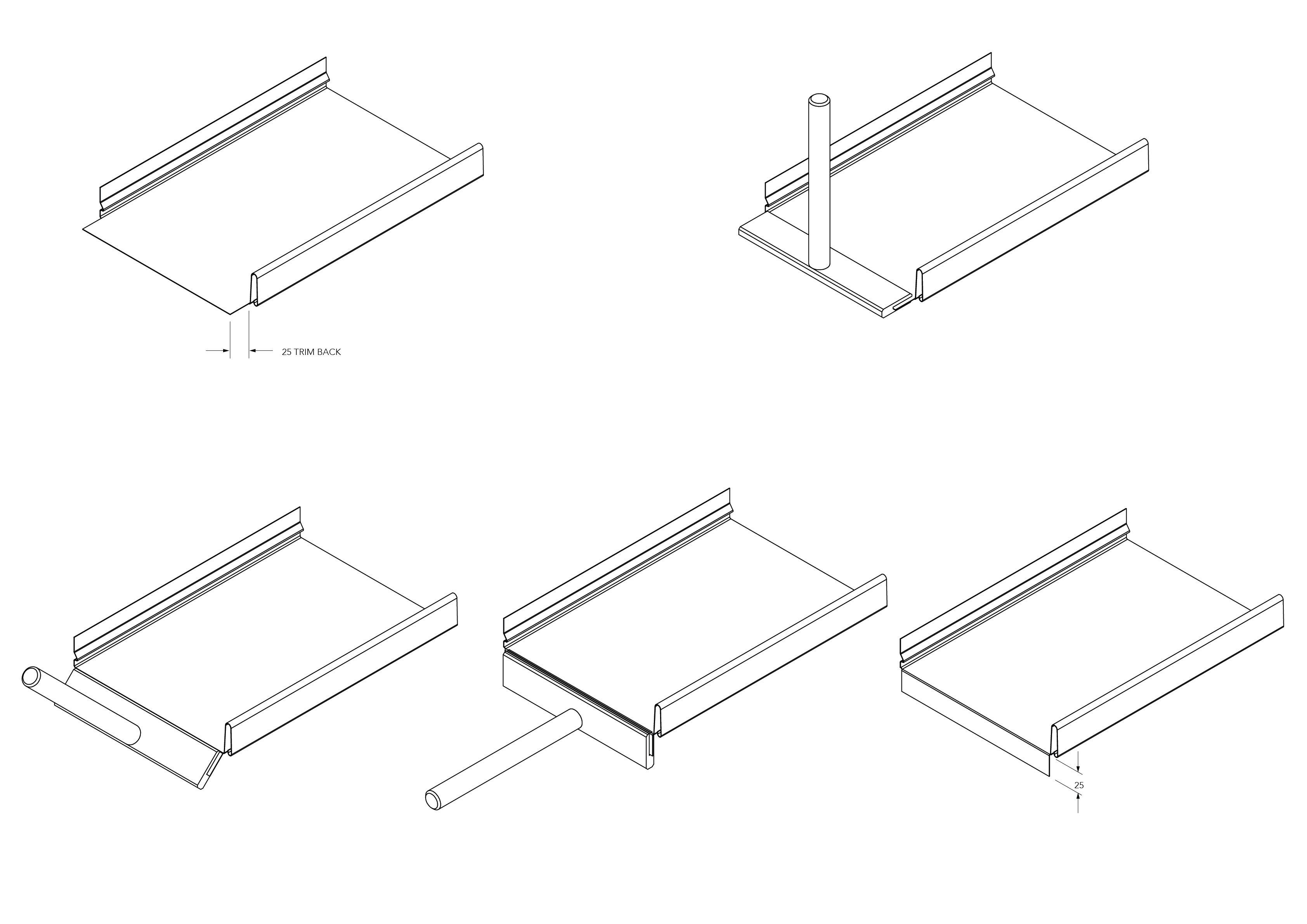
Figure CD ID NC 035
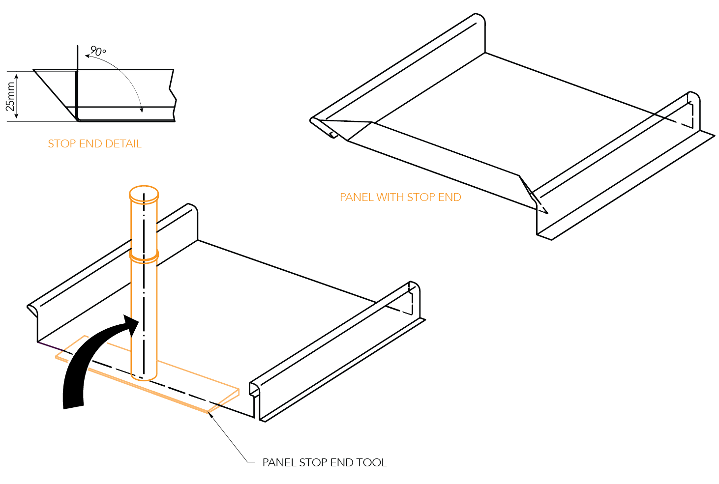
figure CD ID NC 036
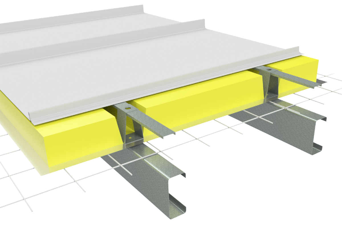
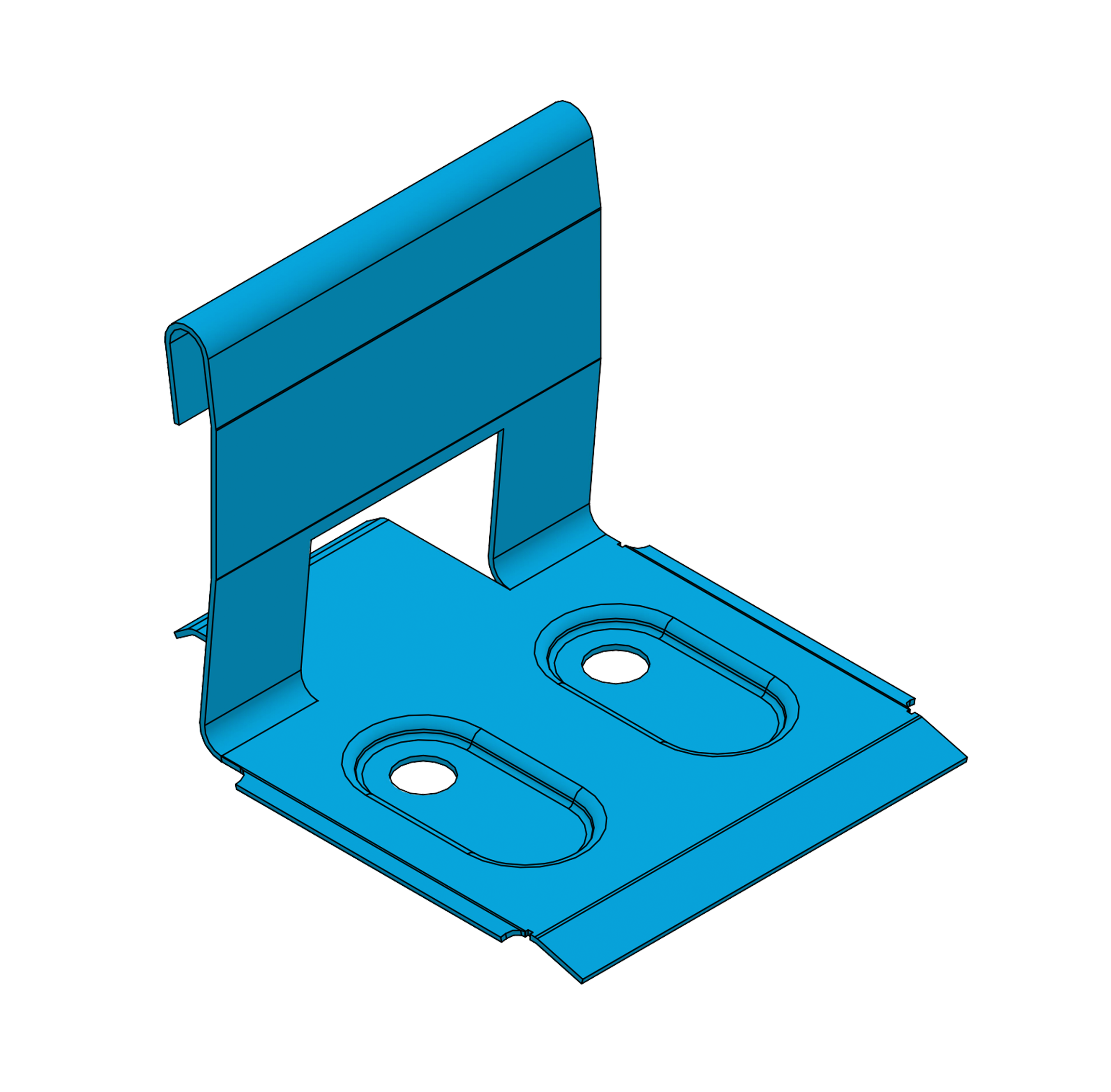
CD INS NC 001
Note:
Image displayed using Shadowline profile