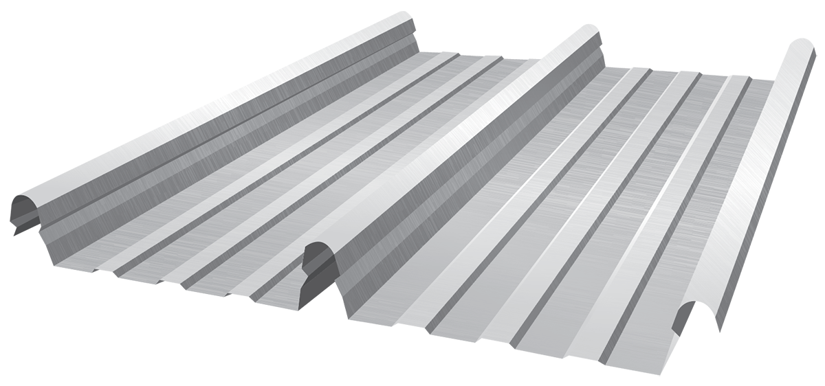
About HiKlip® 630
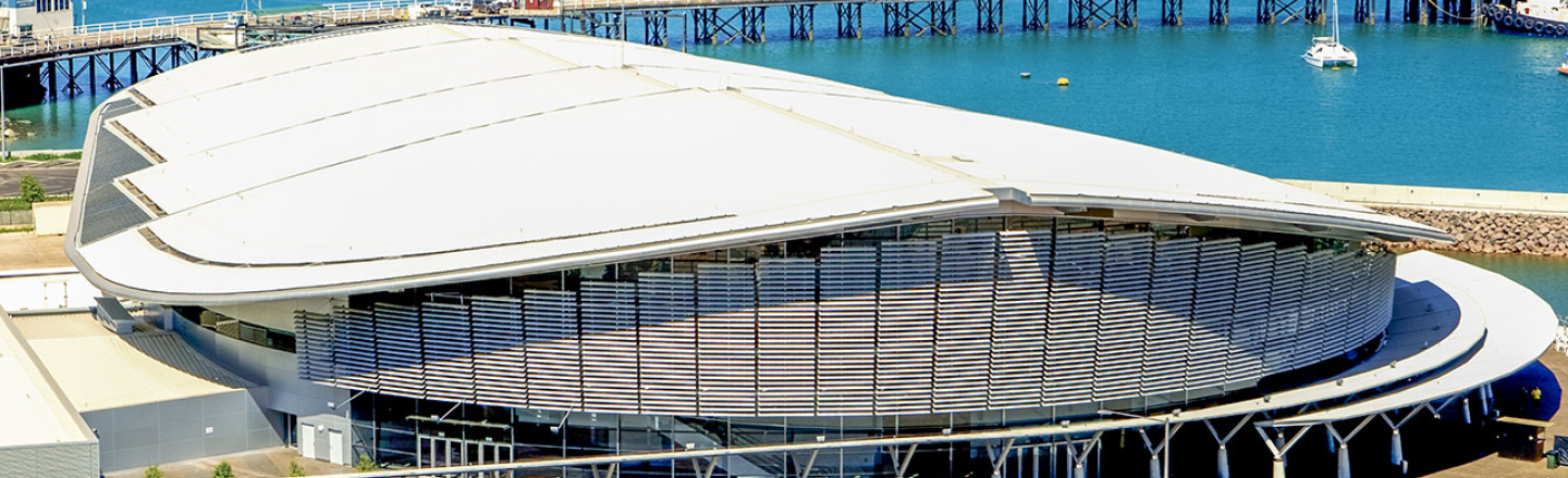
High and mighty, HiKlip® 630 is the largest water-carrying concealed-fixed roofing in Australia. Purposely built to survive the strongest stormy weather for major commercial, industrial and domestic projects. HiKlip® 630 ensures ultimate protection, strength and durability, with large span capabilities that deliver on value, ensuring fewer purlins and lower costs.
Stylish as well as strong, HiKlip® 630 has been described by architects as striking, imposing and bold. Available in a range of COLORBOND® steel light and heavy gauge colours, HiKlip® 630 is truly aesthetically pleasing. HiKlip® 630 can be produced with the Fielders Mobile Mill, available to be made onsite and in real time to suit the required length.
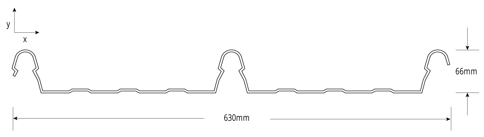
Material Specifications
| Property | Notes | |||
| Base Metal Thickness (mm) | 0.42 | 0.48 | BMT | |
| Total Coated Thickness (mm) | 0.47* | 0.53* | TCT | |
| Mass / Unit Length | ZINCALUME® | 3.26 | 3.70 | kg/m |
| COLORBOND® | 3.32* | 3.76* | ||
| Mass / Unit Area | ZINCALUME® | 5.17 | 5.87 | kg/m2 |
| COLORBOND® | 5.49* | 6.23* | ||
| 2nd moment of area about principal axis (103 mm4) | Ix | 212 | 242 | |
| Iy | 16650 | 19030 | ||
| Section modulus about principal axis (103 mm3) | Zx | 5 | 5 | |
| Zy | 49 | 55 | ||
| Warping Constant (109 mm6) | Iw | 10 | 11 | |
| Torsion Constant (mm4) | J | 23 | 35 | |
| Minimum Yield Strength | G550 | Base Steel Designation | ||
| Coating Class | Z600 (Heritage Galvanised) AM100 (COLORBOND® Steel) AM125 (ZINCALUME®) AM150 (COLORBOND® Ultra Steel) Z450 (Galvanised) | Minimum Coating g/m2 of Zinc - Aluminium |
||
| Coverage (mm) | 630 | |||
| Tolerance | Sheet Length ±7mm Cover Width ±4mm | |||
| Thermal Expansion | 2.9mm average per 5m at 50°C change | |||
- HiKlip® 630 is manufactured from materials in accordance to AS 1397 and AS 2728. It is to be installed in accordance with AS 1562 and HB 39.
- The sectional properties are theoretical values per sheet width. These properties are gross values only.
- *is based on Standard COLORBOND®; single-sided material. For other painted steel options please contact a Fielders® representative.
Rainfall Capacity
For further information, please refer to sections "Rainfall Intensity" and "Water Carrying Capacity and Rainwater Run-Off".
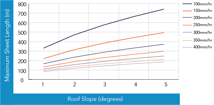
Figure HK RC CY 001
Cyclonic Testing
Fielders® have undertaken cyclonic testing of the HiKlip® 630 profile in accordance with the Low-High-Low (LHL) cyclonic testing method in the NCC (BCA).
The cyclonic wind load capacities for HiKlip® 630 roofing profile is shown in the table below.
Wind Load Capacity: Strength Limit State: 0.42mm BMT
| Span (mm) | End Span (kPa) | Internal Span (kPa) |
| 450 | 11.61 | - |
| 600 | 9.51 | 11.18 |
| 900 | 6.22 | 8.05 |
| 1200 | 4.13 | 5.72 |
| 1500 | 3.26 | 4.21 |
| 1800 | - | 3.51 |
Notes:
- Values are based on fixing into steel supports with a minimum thickness of 1.5mm.
- Values in italics are estimates based on trend lines fitted to the test data.
- Values are based on no insulation under the sheeting.
Wind Load Capacity: Strength Limit State: 0.48mm BMT
| Span (mm) | End Span (kPa) | Internal Span (kPa) |
| 450 | 13.07 | - |
| 600 | 11.09 | 12.59 |
| 900 | 7.79 | 9.86 |
| 1200 | 5.36 | 7.47 |
| 1500 | 3.81 | 5.42 |
| 1800 | - | 3.70 |
Notes:
- Values are based on fixing into steel supports with a minimum thickness of 1.5mm.
- Values in italics are estimates based on trend lines fitted to the test data.
- Values are based on no insulation under the sheeting.
Figure HK CY 001 End Spans, Internal Spans and Overhangs illustrates the terminology end spans, internal spans, and overhangs and their reference to the supporting substructure. This terminology has been used in the following Maximum Recommended Span and Wind Load Capacity tables.
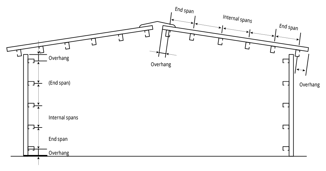
Figure HK CY 001 End Spans, Internal Spans and Overhangs
Maximum Allowable Roof Spans for building heights ≤ 5m: Region C
| Terrain Category | Roof Area Notation & Uplift (kPa)* | 0.42 mm BMT | 0.48 mm BMT | ||
| End Span (mm) | Internal Span (mm) | End Span (mm) | Internal Span (mm) | ||
| 1 & 2 | D - 4.18 | 1190 | 1510 | 1410 | 1710 |
| F - 5.35 | 1000 | 1260 | 1200 | 1510 | |
| G - 6.53 | 860 | 1080 | 1040 | 1330 | |
| 2.5 | D - 3.54 | 1350 | 1770 | 1580 | 1830 |
| F - 4.54 | 1120 | 1410 | 1330 | 1640 | |
| G - 5.54 | 980 | 1230 | 1170 | 1480 | |
Importance Level 2
Maximum Roof Height H = 5, 10m
External Pressure Coefficient:
Cpe = -0.90 for roofing
Cpe = -0.65 for walling
Internal Pressure Coefficient:
Cpi = 0.7
Local Pressure Factor
KL = 2.0, 1.5, 1.0
Ms = Mt = Md = 1.0
Table HK RS CY 001A - HiKlip® 630 Cyclonic
Notes:
- Values are based on fixing into steel supports with a minimum thickness of 1.5mm.
- Values in italics are estimates based on trend lines fitted to the test data.
- Values are based on no insulation under the sheeting.
Maximum Allowable Roof Spans for building heights ≤ 5m: Region D
| Terrain Category | Roof Area Notation & Uplift (kPa)* | 0.42 mm BMT | 0.48 mm BMT | ||
| End Span (mm) | Internal Span (mm) | End Span (mm) | Internal Span (mm) | ||
| 1 & 2 | D - 6.66 | 850 | 1060 | 1020 | 1310 |
| F - 8.54 | 670 | 840 | 820 | 1060 | |
| G - 10.41 | 530 | 660 | 650 | 830 | |
| 2.5 | D - 5.65 | 960 | 1210 | 1150 | 1460 |
| F - 7.24 | 790 | 990 | 950 | 1230 | |
| G - 8.83 | 650 | 820 | 790 | 1020 | |
Importance Level 2
Maximum Roof Height H = 5, 10m
External Pressure Coefficient:
Cpe = -0.90 for roofing
Cpe = -0.65 for walling
Internal Pressure Coefficient:
Cpi = 0.7
Local Pressure Factor
KL = 2.0, 1.5, 1.0
Ms = Mt = Md = 1.0
Table HK RS CY 001B - HiKlip® 630 Cyclonic
Notes:
- Values are based on fixing into steel supports with a minimum thickness of 1.5mm.
- Values in italics are estimates based on trend lines fitted to the test data.
- Values are based on no insulation under the sheeting.
Maximum Allowable Roof Spans for building heights between 5m-10m: Region C
| Terrain Category | Roof Area Notation & Uplift (kPa)* | 0.42 mm BMT | 0.48 mm BMT | ||
| End Span (mm) | Internal Span (mm) | End Span (mm) | Internal Span (mm) | ||
| 1 & 2 | D - 4.63 | 1110 | 1400 | 1320 | 1630 |
| F - 5.93 | 930 | 1160 | 1110 | 1420 | |
| G - 7.23 | 790 | 990 | 960 | 1230 | |
| 2.5 | D - 4.13 | 1200 | 1520 | 1420 | 1710 |
| F - 5.30 | 1010 | 1270 | 1200 | 1510 | |
| G - 6.46 | 870 | 1090 | 1050 | 1340 | |
Importance Level 2
Maximum Roof Height H = 5, 10m
External Pressure Coefficient:
Cpe = -0.90 for roofing
Cpe = -0.65 for walling
Internal Pressure Coefficient:
Cpi = 0.7
Local Pressure Factor
KL = 2.0, 1.5, 1.0
Ms = Mt = Md = 1.0
Table HK RS CY 002A - HiKlip® 630 Cyclonic
Notes:
- Values are based on fixing into steel supports with a minimum thickness of 1.5mm.
- Values in italics are estimates based on trend lines fitted to the test data.
- Values are based on no insulation under the sheeting.
Maximum Allowable Roof Spans for building heights between 5m-10m: Region D
| Terrain Category | Roof Area Notation & Uplift (kPa)* | 0.42 mm BMT | 0.48 mm BMT | ||
| End Span (mm) | Internal Span (mm) | End Span (mm) | Internal Span (mm) | ||
| 1 & 2 | D - 7.38 | 780 | 970 | 940 | 1210 |
| F - 9.46 | 600 | 750 | 730 | 940 | |
| G - 11.54 | 450 | 570 | 560 | 710 | |
| 2.5 | D - 6.59 | 860 | 1070 | 1030 | 1320 |
| F - 8.45 | 680 | 850 | 830 | 1070 | |
| G - 10.30 | 540 | 670 | 660 | 840 | |
Importance Level 2
Maximum Roof Height H = 5, 10m
External Pressure Coefficient:
Cpe = -0.90 for roofing
Cpe = -0.65 for walling
Internal Pressure Coefficient:
Cpi = 0.7
Local Pressure Factor
KL = 2.0, 1.5, 1.0
Ms = Mt = Md = 1.0
Table HK RS CY 002B - HiKlip® 630 Cyclonic
Notes:
- Values are based on fixing into steel supports with a minimum thickness of 1.5mm.
- Values in italics are estimates based on trend lines fitted to the test data.
- Values are based on no insulation under the sheeting.
Maximum Allowable Wall Spans for building heights ≤ 5m: Region C
| Terrain Category | Roof Area Notation & Uplift (kPa)* | 0.42 mm BMT | 0.48 mm BMT | ||
| End Span (mm) | Internal Span (mm) | End Span (mm) | Internal Span (mm) | ||
| 1 & 2 | D - 4.18 | 1350 | 1780 | 1580 | 1830 |
| F - 5.35 | 1150 | 1450 | 1370 | 1670 | |
| G - 6.53 | 1020 | 1280 | 1220 | 1530 | |
| 2.5 | D - 3.54 | 1600 | 1750 | 1600 | 1940 |
| F - 4.54 | 1290 | 1670 | 1520 | 1790 | |
| G - 5.54 | 1140 | 1440 | 1350 | 1660 | |
Importance Level 2
Maximum Roof Height H = 5, 10m
External Pressure Coefficient:
Cpe = -0.90 for roofing
Cpe = -0.65 for walling
Internal Pressure Coefficient:
Cpi = 0.7
Local Pressure Factor
KL = 2.0, 1.5, 1.0
Ms = Mt = Md = 1.0
Table HK WS CY 001A - HiKlip® 630 Cyclonic
Notes:
- Values are based on fixing into steel supports with a minimum thickness of 1.5mm.
- Values in italics are estimates based on trend lines fitted to the test data.
- Values are based on no insulation under the sheeting.
Maximum Allowable Wall Spans for building heights ≤ 5m: Region D
| Terrain Category | Roof Area Notation & Uplift (kPa)* | 0.42 mm BMT | 0.48 mm BMT | ||
| End Span (mm) | Internal Span (mm) | End Span (mm) | Internal Span (mm) | ||
| 1 & 2 | D | 970 | 1210 | 1160 | 1460 |
| F | 820 | 1020 | 980 | 1260 | |
| G | 690 | 860 | 840 | 1080 | |
| 2.5 | D | 1080 | 1370 | 1290 | 1600 |
| F | 930 | 1160 | 1120 | 1420 | |
| G | 810 | 1010 | 970 | 1250 | |
Importance Level 2
Maximum Roof Height H = 5, 10m
External Pressure Coefficient:
Cpe = -0.90 for roofing
Cpe = -0.65 for walling
Internal Pressure Coefficient:
Cpi = 0.7
Local Pressure Factor
KL = 2.0, 1.5, 1.0
Ms = Mt = Md = 1.0
Table HK WS CY 001B - HiKlip® 630 Cyclonic
Notes:
- Values are based on fixing into steel supports with a minimum thickness of 1.5mm.
- Values in italics are estimates based on trend lines fitted to the test data.
- Values are based on no insulation under the sheeting.
Maximum Allowable Wall Spans for building heights between 5m-10m: Region C
| Terrain Category | Roof Area Notation & Uplift (kPa)* | 0.42 mm BMT | 0.48 mm BMT | ||
| End Span (mm) | Internal Span (mm) | End Span (mm) | Internal Span (mm) | ||
| 1 & 2 | D - 4.63 | 1250 | 1590 | 1470 | 1760 |
| F - 5.93 | 1070 | 1350 | 1280 | 1590 | |
| G - 7.23 | 950 | 1190 | 1130 | 1440 | |
| 2.5 | D - 4.13 | 1370 | 1820 | 1590 | 1840 |
| F - 5.30 | 1160 | 1470 | 1380 | 1680 | |
| G - 6.46 | 1030 | 1290 | 1220 | 1540 | |
Importance Level 2
Maximum Roof Height H = 5, 10m
External Pressure Coefficient:
Cpe = -0.90 for roofing
Cpe = -0.65 for walling
Internal Pressure Coefficient:
Cpi = 0.7
Local Pressure Factor
KL = 2.0, 1.5, 1.0
Ms = Mt = Md = 1.0
Table HK WS CY 002A - HiKlip® 630 Cyclonic
Notes:
- Values are based on fixing into steel supports with a minimum thickness of 1.5mm.
- Values in italics are estimates based on trend lines fitted to the test data.
- Values are based on no insulation under the sheeting.
Maximum Allowable Wall Spans for building heights between 5m-10m: Region D
| Terrain Category | Roof Area Notation & Uplift (kPa)* | 0.42 mm BMT | 0.48 mm BMT | ||
| End Span (mm) | Internal Span (mm) | End Span (mm) | Internal Span (mm) | ||
| 1 & 2 | D | 880 | 1120 | 1070 | 1370 |
| F | 740 | 930 | 900 | 1160 | |
| G | 620 | 770 | 750 | 970 | |
| 2.5 | D | 970 | 1220 | 1170 | 1470 |
| F | 820 | 1030 | 990 | 1270 | |
| G | 700 | 870 | 850 | 1090 | |
Importance Level 2
Maximum Roof Height H = 5, 10m
External Pressure Coefficient:
Cpe = -0.90 for roofing
Cpe = -0.65 for walling
Internal Pressure Coefficient:
Cpi = 0.7
Local Pressure Factor
KL = 2.0, 1.5, 1.0
Ms = Mt = Md = 1.0
Table HK WS CY 002B - HiKlip® 630 Cyclonic
Notes:
- Values are based on fixing into steel supports with a minimum thickness of 1.5mm.
- Values in italics are estimates based on trend lines fitted to the test data.
- Values are based on no insulation under the sheeting.
Allowable Spans
The allowable roof spans for the HiKlip® 630 roofing profile in Regions C and D are shown in Table HK RS CY 001 and Table HK RS CY 002.
The allowable spans have been determined from tests carried out in accordance with NCC (BCA) 2016 Specification B1.2 for the LHL cyclonic testing method, AS 1170.2-2011 and AS 4040.0-1992.
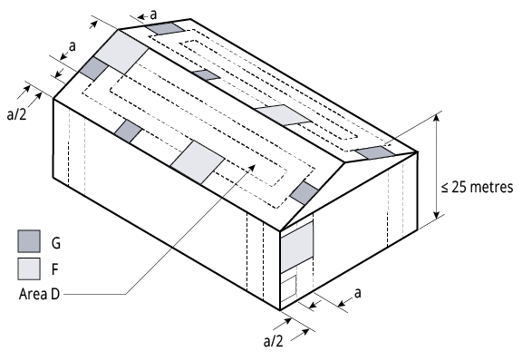
Figure HK CY Local Pressure Factors 002
Note:
1. The local pressure factors (KL) are shown in Figure HK CY Local Pressure Factors 002 are not applicable at the ridge where the roof pitch is less than 10°. The value of ‘a’ is the minimum of 0.2 breadth, 0.2 width or the height.
Insulation
Care needs to be taken when installing insulation with roof sheeting. When insulation thickness up to 50mm are installed the screws detailed in Table HK CF CY 001 may need to be increased depending on the thickness and density of the insulation. When the screw is properly tightened into metal there should be a minimum of three (3) threads protruding past the support being fixed in to. For timber the screw must penetrate the timber as much as the screws detailed in Table HK CF CY 001 do without insulation.
For insulation thicknesses greater than 50mm Fielders® recommend the use of a thermal spacer to help maintain Rw values as well as minimising any bulging in the profile caused by the insulation.
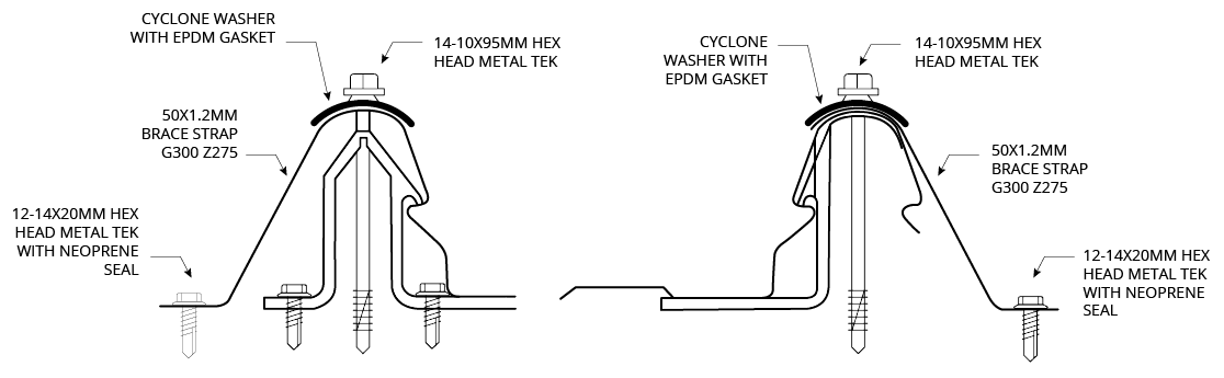
Fixing of Cladding
Fasteners must be selected to match the life expectancy of the cladding material. Recommendations from fastener manufacturers should be sought. Only fasteners complying with AS 3566:2002 and those that are compatible with the roofing material should be used for its fastening.
All fasteners used externally should be fitted with an EPDM seal. Do not use punches to form fastener holes. For a concealed-fixed cladding, the clips are fastened to the support at the base of each rib, as shown in Figure 2.7.C. Fasteners used in the clip fixing is shown in Table HK CF CY 001.
For further information on the HiKlip® 630 roofing profile, including installation procedures, refer to the “installation procedure”.
Fasteners Spacing
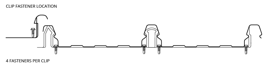
Figure HK CY HiKlip® 630 clip fastener locations 003
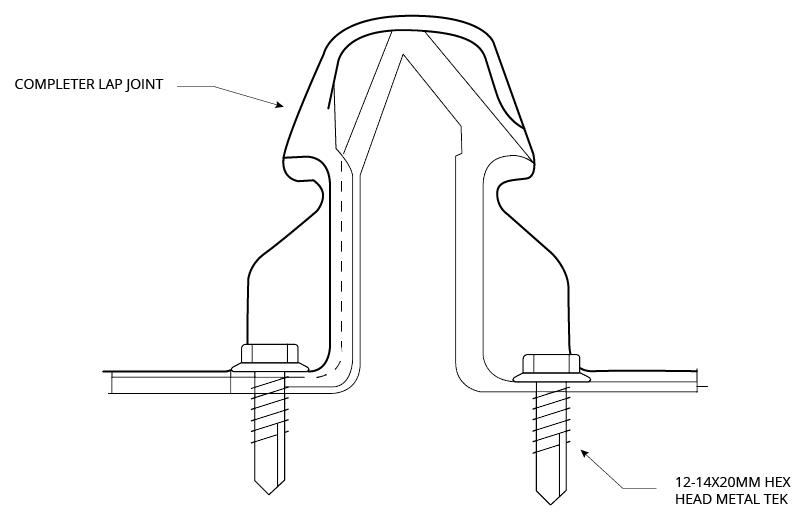
Concealed Fastening
Unique double-clip action
Only HiKlip® 630 features an over-and-under double clipping action on the side lap for added strength to withstand the strongest winds. And therefore, because the clips and brackets allow the sheet to move with temperature changes, you do not need step/expansion joints.
Further details are available in section “Comparative Analysis: Concealed Fix vs. Screw Fix”.

Figure HK CY Double-clip action ensures maximum strength 007
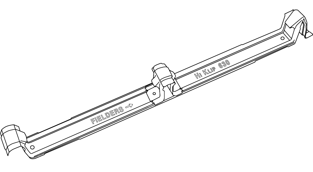
Figure HK CY HiKlip® Concealed Fix Clipping System 008
Laying HiKlip® 630
Step 1
Fix the first of the HiKlip® 630 clips perpendicular to the gutter in a straight line using the correct fasteners. Use a string line or the edge of the first sheet to ensure straightness. Care should be taken so that the overlap is facing away from the prevailing weather.
Step 2
Locate the first sheet above the clips ensuring that the overhang into the gutter is correct. Push downwards on the sheet until the decking is secured at every clip. Do not use excessive force.
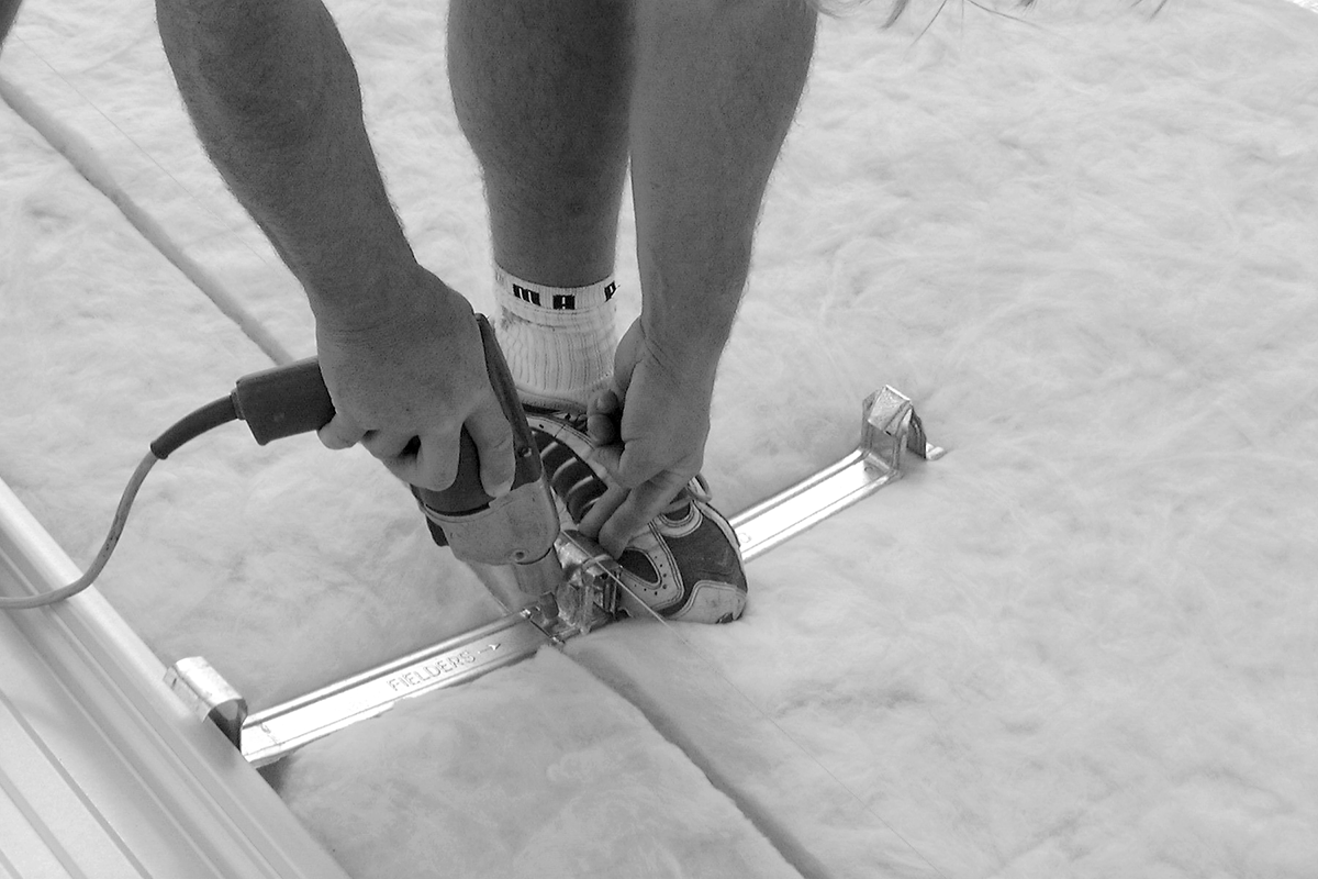
Figure HK CY Clips Located By Fixing Centre Screw First 004
Step 3
Lap the next HiKlip® 630 clip over the top of the male rib, ensuring that the sheet being laid is parallel to the previous sheet and perpendicular to the gutter line. Fasten this first and fix the remaining two holes as previously done. Fasten all clips in this manner.

Figure HK CY HiKlip®Clips Over The Top Of The Male Rib 005
Step 4
Lay the next sheet of HiKlip® 630 as previously described. Checks should be carried out periodically to ensure the deck-ing is installed squarely. This can be done by comparing the coverage at the ridge to that at the gutter line or by using a string line. At the end of the purlins, cut the deck and clip to suit.
Step 5
Turn up the HiKlip® 630 pans at the ridge line. On lower pitches the pans should be turned down at the gutter line.
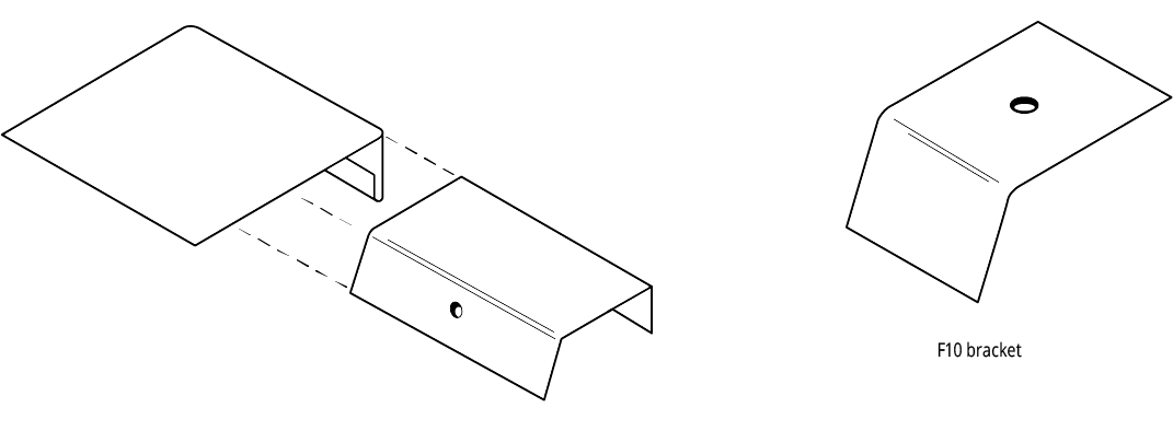
Step 6
Flash the roof with compatible products using F10 brackets and sliding brackets as necessary to allow for thermal expansion and contraction.
Step 7
Clean the roof daily during construction as per Fielders® maintenance guide, ensuring the removal of all swarf, pop rivets and fasteners.
Figure HK CY Clips Located Over HiKlip® 630 Male Rib 006
Turning of Roof Sheeting Ends
Refer to section “Flashings, Cappings & Ends of Sheets”.
Designing Without Step Joints
For further information regarding the design of HiKlip® 630 roofs without step joints, please see section "Long Length Roofing Solutions".
Maximum Roof Length
See section “Thermal Expansion and Contraction of Steel Sheeting”.
Curving HiKlip® 630
For details regarding spring curving of HiKlip® 630 sheets, please see section “Curving of Steel Decks”.
HiKlip 630® Flashings & Details
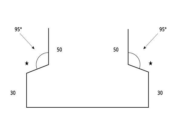
Masonry Parapet Side Wall (Low)
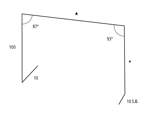
Product Code: HK1
Masonry Parapet Side Wall (High)
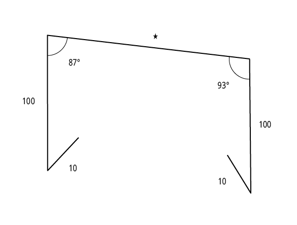
Product Code: HK2
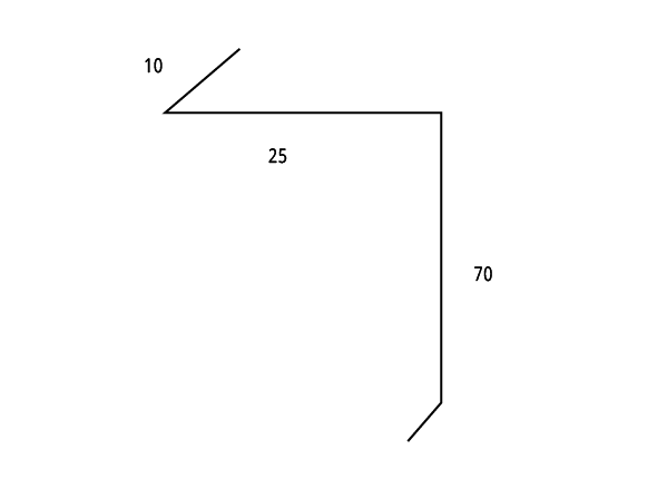
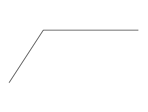
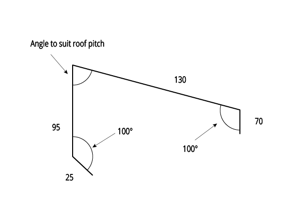
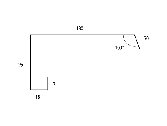
Apron Flashings
Product Code: HK3
Girth 330
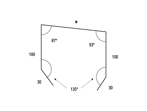
Overflashing
Product Code: HK4
Girth 112
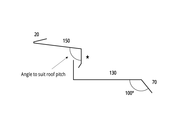
Headwall Apron Flashing
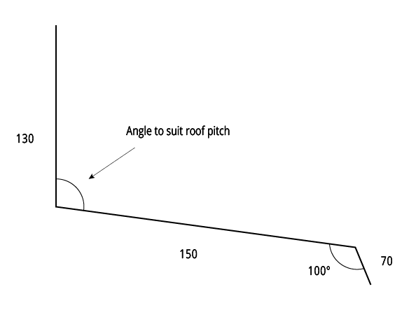
Product Code: HK5
Girth 350
Soaker Gutter
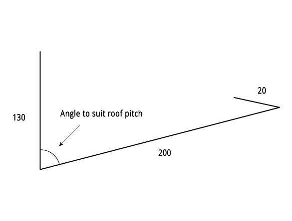
Product Code: HK6
Girth 350
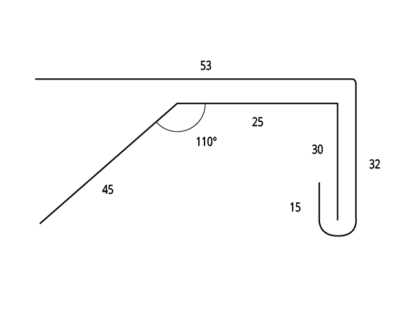
Soffit Corner Flashing
Product Code: HK7
Girth 211
Shoe Flashing
Product Code: HK8
Bracket
Product Code: HK10
Valley Gutter

Product Code: HK11
Girth 340
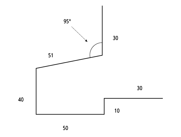
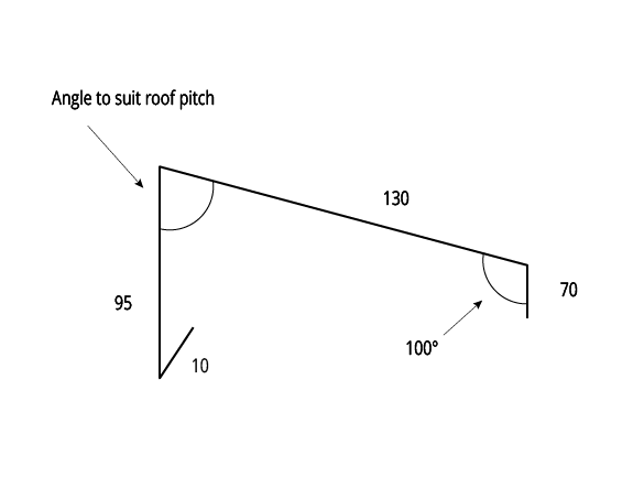
Under Over Flashing

Product Code: HK12
Girth 330
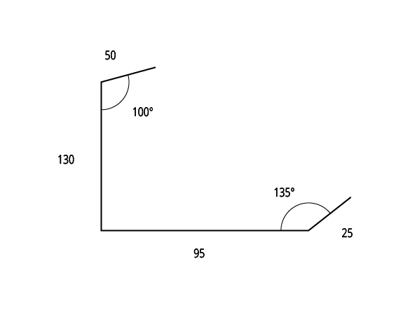
Mansard Roof Flashing
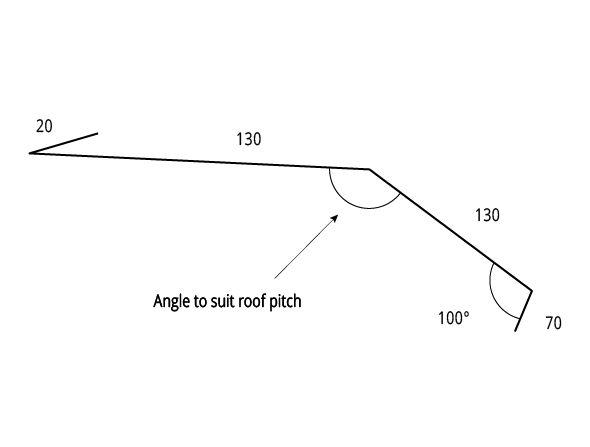
Product Code: HK13
Girth 330
Industrial Door Jamb Flashing
Product Code: HK14
Girth 182
Apex Capping
Type 1
Product Code: HK17
Girth 300
Apex Capping
Type 2
Product Code: HK18
Girth 285
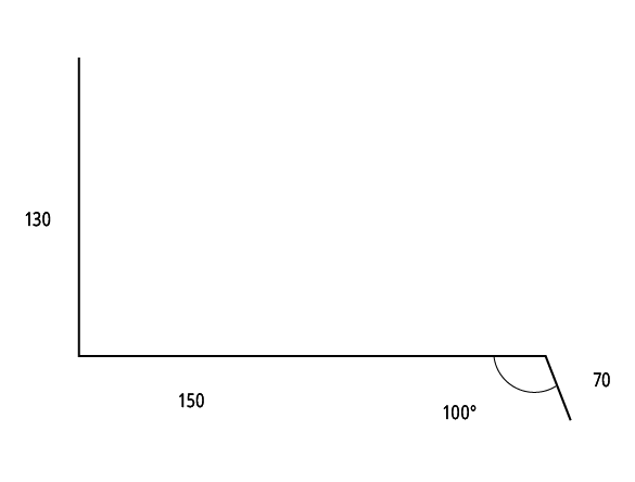
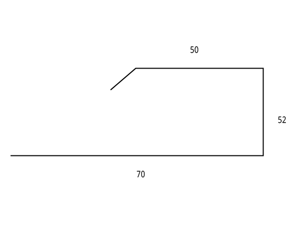
Back Channel
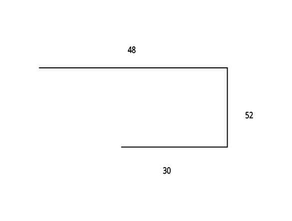
Product Code: HK19
Girth 130
Barge Capping Steel Construction
Product Code: HK20
Girth 300
Barge Capping
Product Code: WK22
Girth 300
Framed Parapet Capping
Product Code:HK23
Two Piece Step Flashing
Product Code: HK24
Sliding Bracket
Product Code: HK25
Table HK FD CY 001
Notes:
1. *denotes size to be determined by application. All sizes are in mm and should be used as a guide only. They should be measured on-site to determine actual size.
2. S.B. denotes ‘ Slight Break’.
3. Also refer to “Typical Roofing Details”.