
- nsw
- vic
- sa
- wa
You need to select a state...
SK NOTE: I was thinking of putting some placeholder blocks here to indicate there was more content to come (rough example below). But that is being used quite a lot now in apps where content loads automatically - so would be pretty misleading and may lead to a user waiting for something to happen. So still thinking of a better idea here...

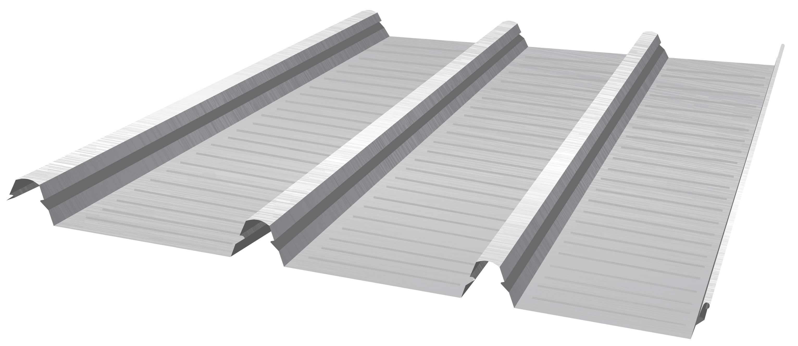
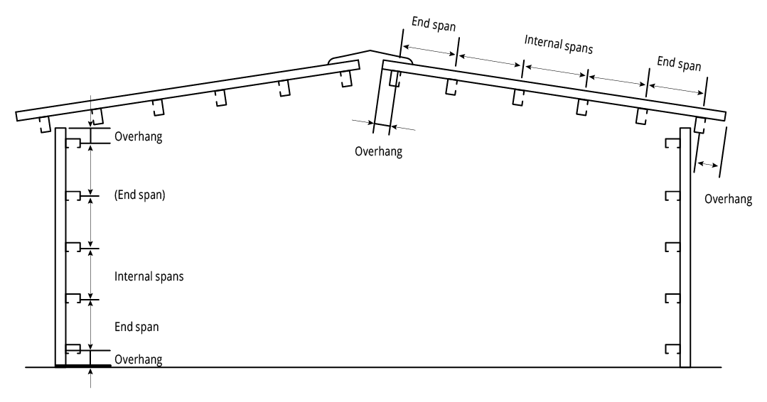
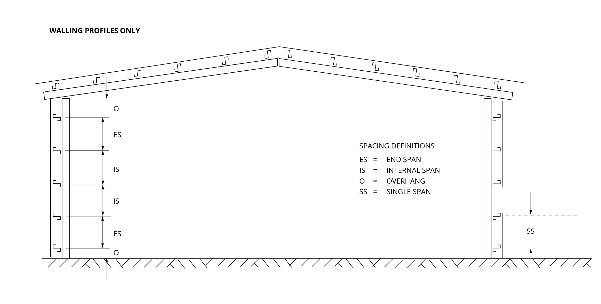
Figure KK NC 002 End Spans, Internal Spans and Overhangs
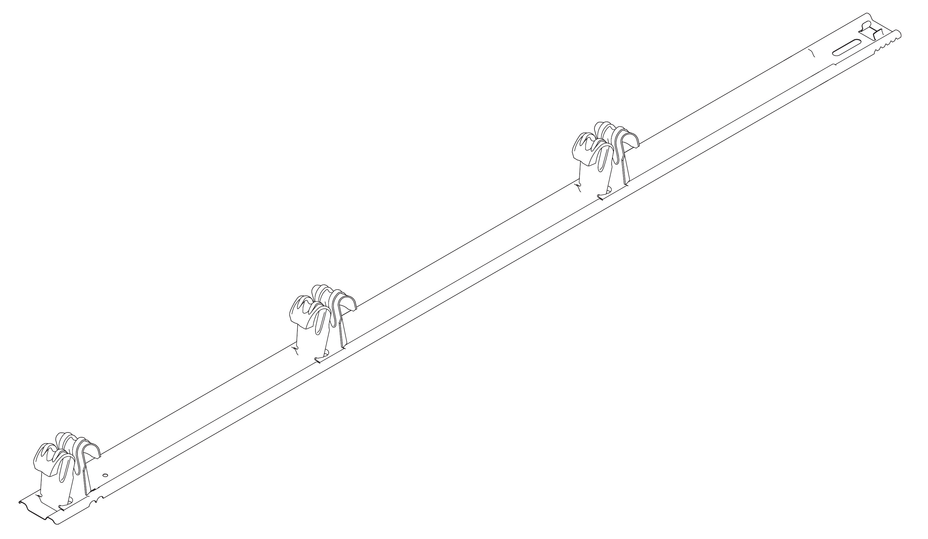
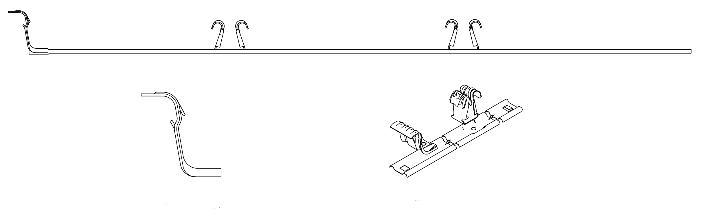
Figure KK MKII KingKlip® NY 001 - Concealed Fix Clipping System

Figure 1
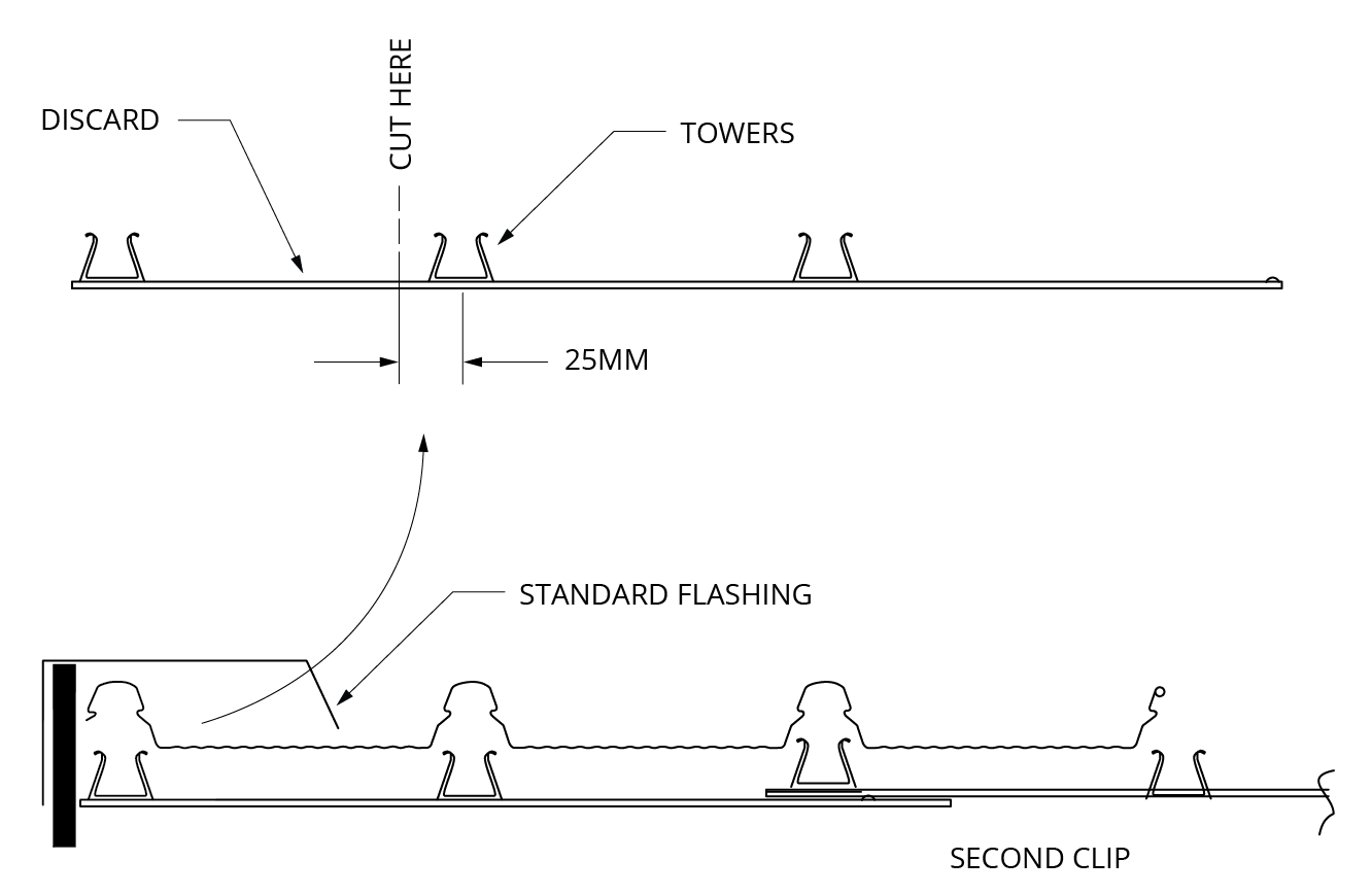
Figure 2a: M1 Clip
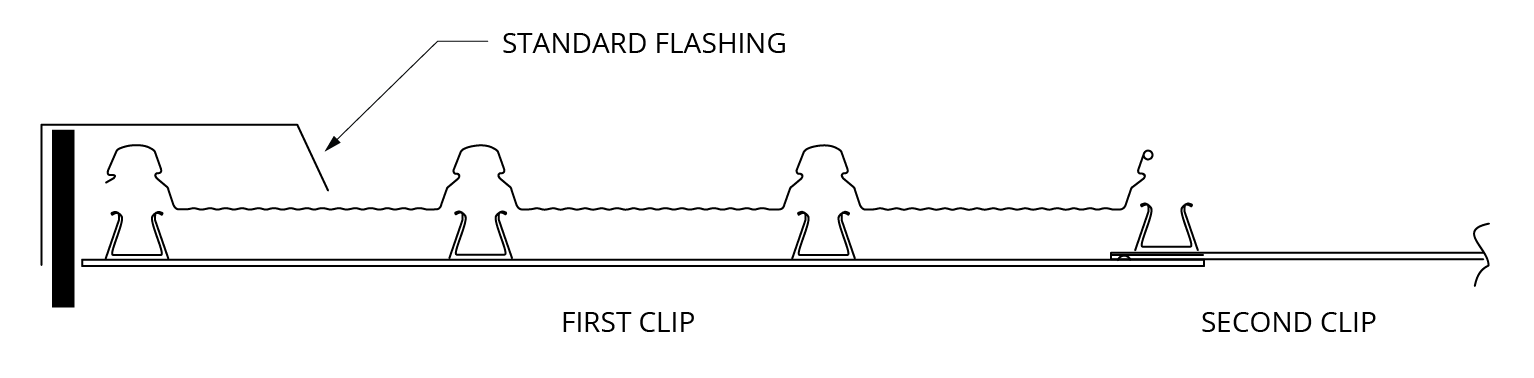
Figure 2b: M2 Clip

Figure 3
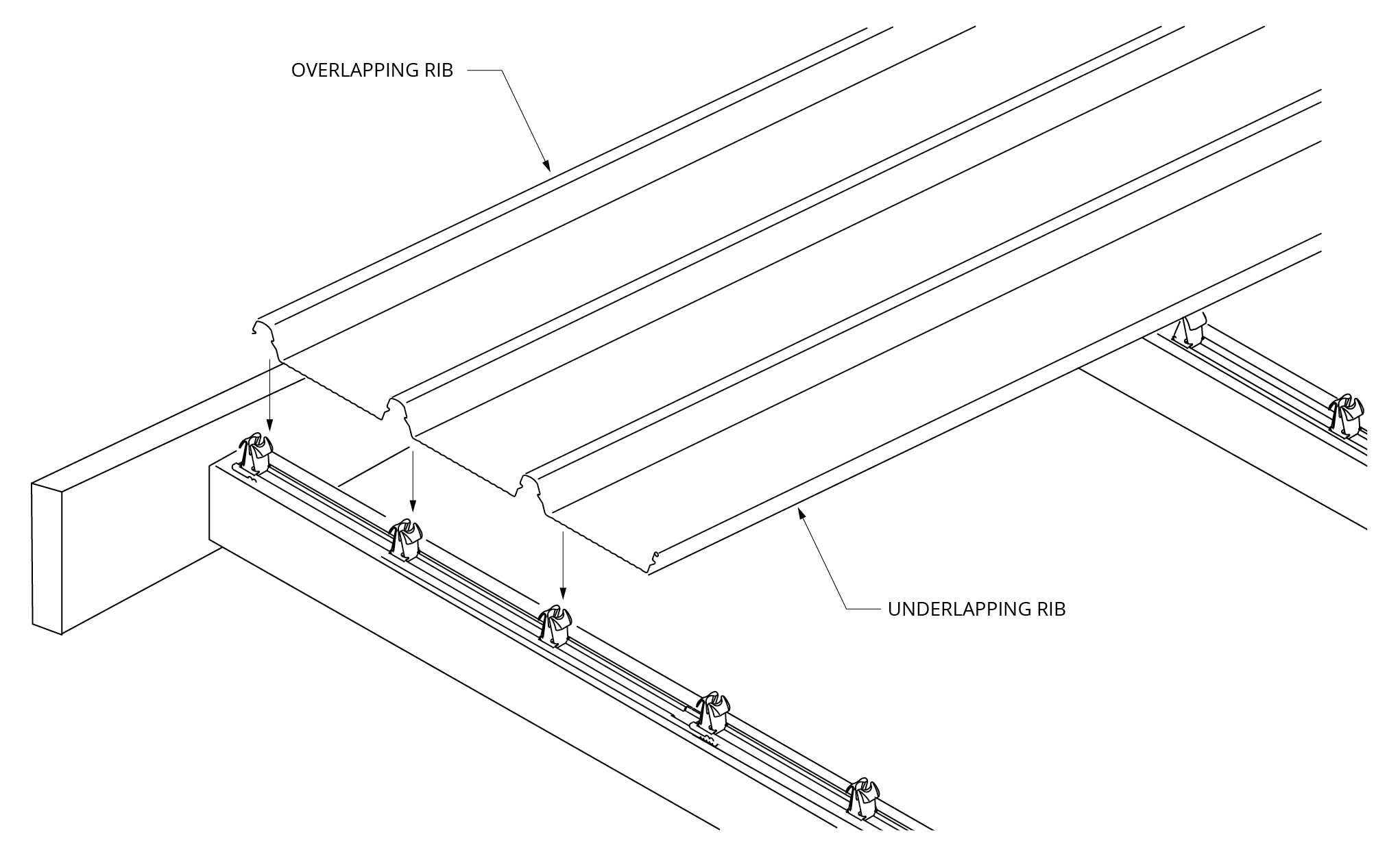
Figure 4

Figure 5
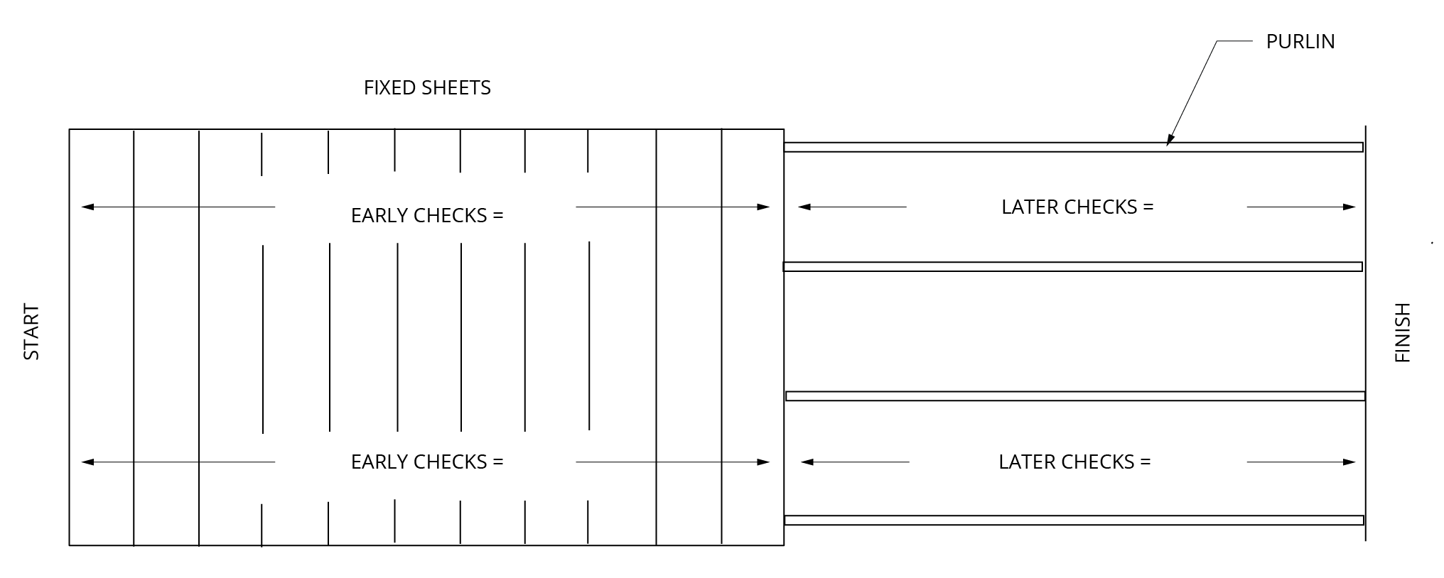
Figure 6
Benefits of King-Lap™
- Low profile system maintains roof aesthetics with clean, long run roof lines for KingKlip® 700 cladding.
- Avoids step joins and purlin complexity to provide a cost effective way to achieve a long-length roofing design, even when using shorter roof sheets.
- Fast and easy to install – minimal change to current KingKlip® 700 installation practice.
- Tested and proven in our NATA-accredited testing facility. If installed correctly, will preserve all existing roofing warranties and capacities.
- Safe and effective weather resistant seal.
- Suitable for cyclonic applications.
- Readily allows for thermal movement of roof sheets.
- As a stand alone solution, compatible with translucent sheeting.
King-Lap™ is comprised of brackets which are fixed to the ribs and two separate weather strips.
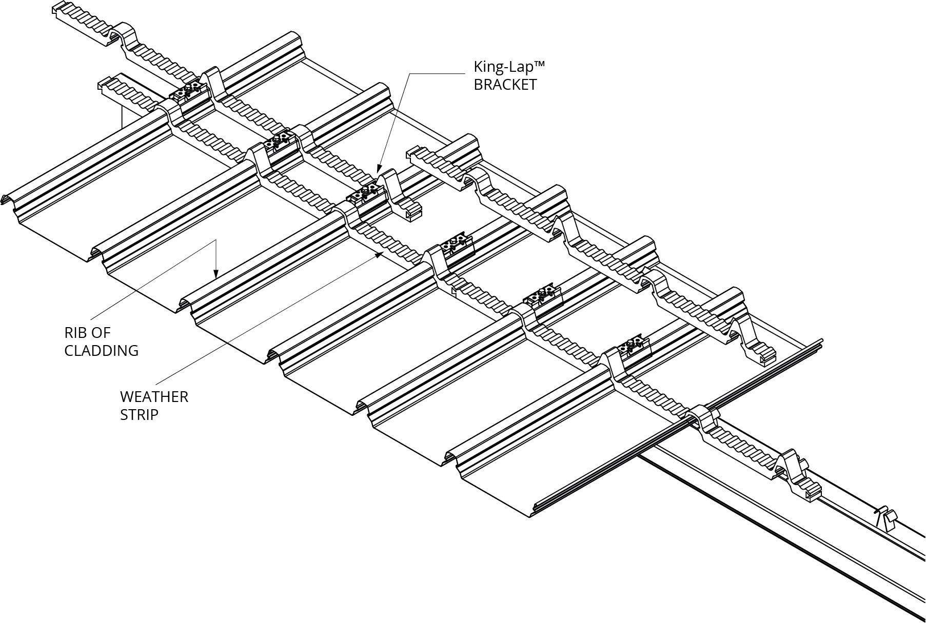
Figure 1
Background on thermal expansion
All metals expand and contract with changes in temperature. Although steel is by far the least affected of all the metals commonly used for roof and wall cladding, the changes in length experienced in very long runs of roofing are significant.
When a King-Lap™ is used, the length of each individual sheet is necessarily shorter, thus reducing the impact of thermal movement.
King-Lap™ is an expansion joint/lap joint hybrid
An expansion joint involves overlapping the ends of the upper sheets over the ends of the lower sheets. With King-Lap™, no extra purlin is needed at the joint.
A weather strip provides protection from wind-blown rain and is made from closed cell polyethylene foam. It is used between the upper and lower sheets and laid in pairs, one either side of the King-Lap™ bracket to provide a weather resistant barrier from wind driven rainwater. It also provides air flow to reduce likelihood of condensate build-up.
The King-Lap™ bracket is a pressed metal component that saddles the rib of the KingKlip®700 roofing by engaging the “S” bends of the lower sheet and is clipped into place. The bracket is fixed to the lower sheet by fasteners through the pre-punched holes however this allows the upper sheet to move relative to the bracket due to thermal expansion.
Testing
Made from Australian-made G550 AZ150 ZINCALUME® steel, King-Lap™ is strong. King-Lap™ has been tested for performance in wind uplift and weather-resistance at Fielders® NATA-accredited materials science testing laboratory. This means you can be confident that King-Lap™ will perform to specification when installed according to our design limitations and installation guidelines.
Wind uplift tests were performed to ensure King-Lap™ clips met the performance standards required.
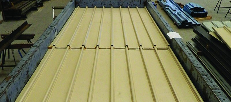
Figure 2
Weather test rig is used to test weather-resistance by blowing simulated wind borne rain.
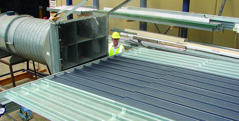
Figure 3
King-Lap™ joint layout and fixing
This will allow normal concealed fastening at the support and thus allowing thermal movement to occur at the King-Lap™. To install the King-Lap™ bracket, locate each King-Lap™ bracket as per Figure 5, then hand press to snap fit each King-Lap™ bracket to the KingKlip®700 (Figure 4a, 4b). For non-cyclonic areas, using a low torque setting on the drill to ensure the cladding is not stripped, secure through the top hole of the King-Lap™ and also through the crest of the lower sheet (Figure 4a). For cyclonic areas, use two fasteners by fixing through the sides of the King-Lap™ bracket into the sides of the rib (Figure 4b).
Weather strips are laid either side of the King-Lap™ brackets and offset (see installation steps).
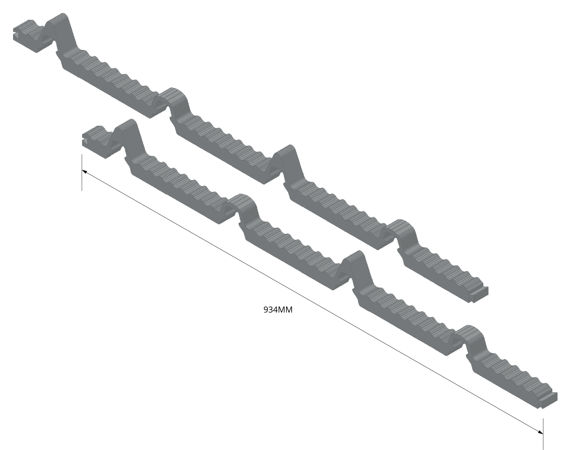
Figure 4
Fixing of King-Lap™ brackets to cladding.
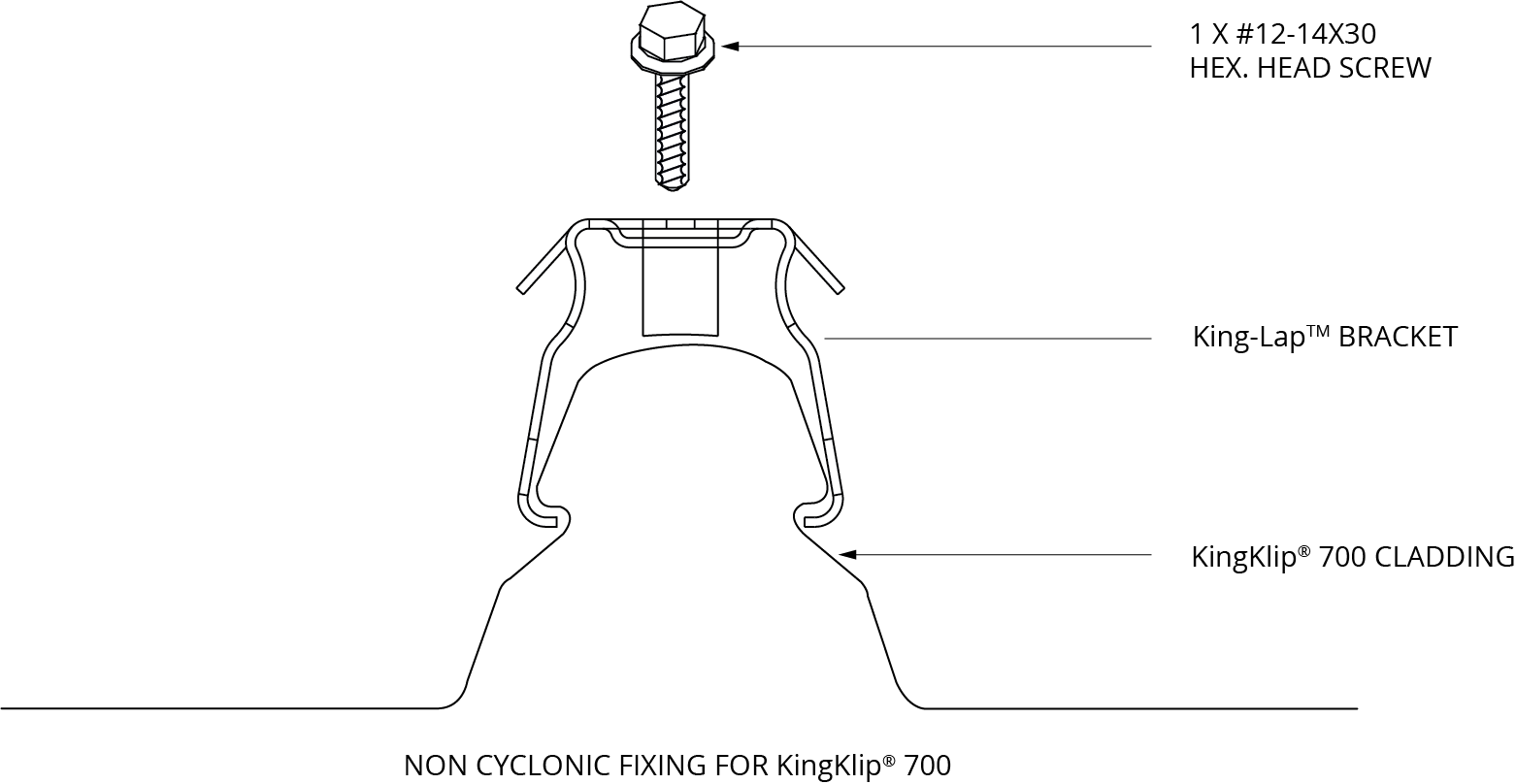
Figure 4a
Fixing of King-Lap™ brackets to cladding.

Figure 4b
Details of King-Lap™ at support.
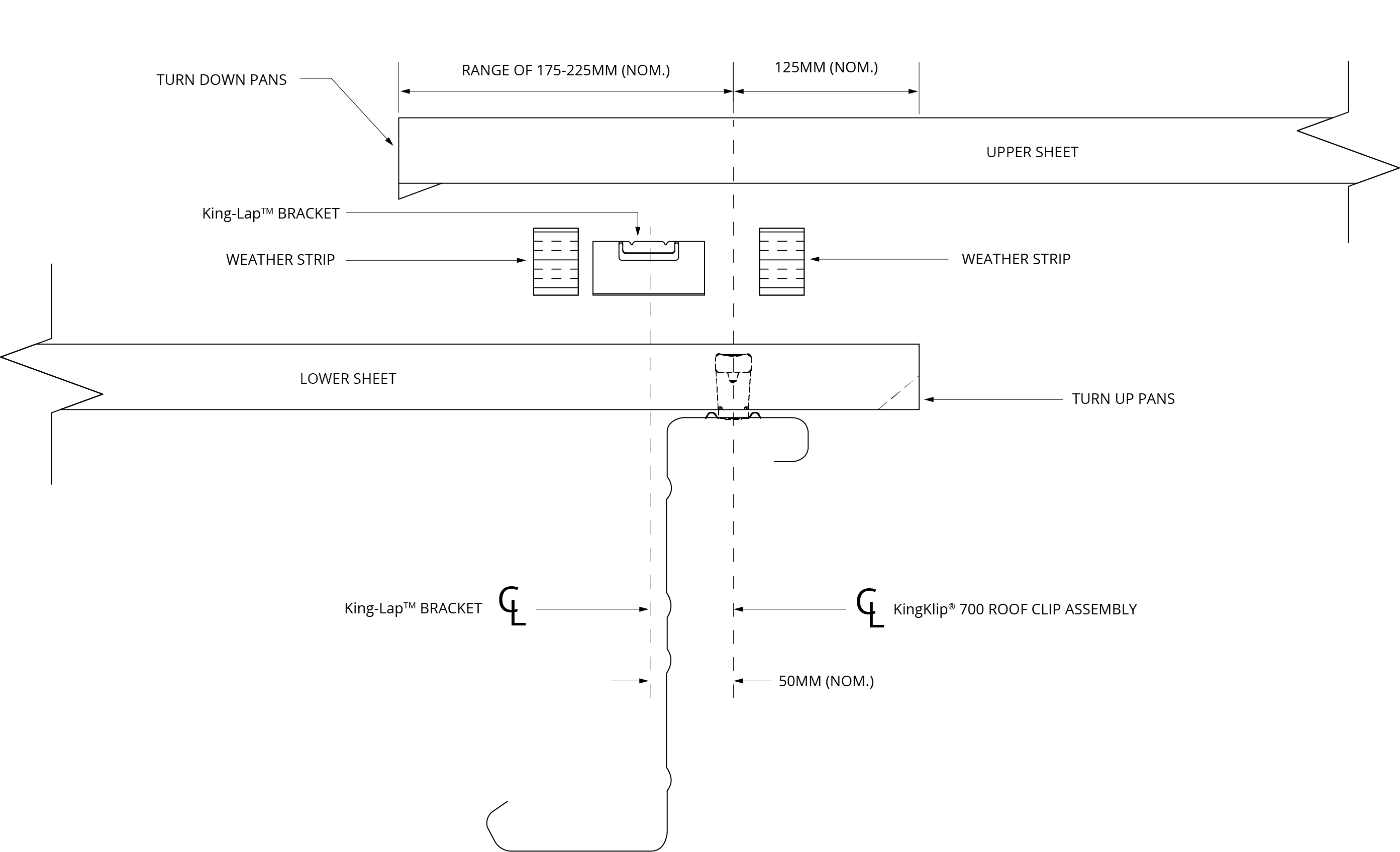
Figure 5
NOTE: The installer must make allowance for added sheet length for upper and lower sheets or any intermediate sheet resulting from multiple joints to construct the joint.
When specifying or ordering, please refer to the layout schematic detailed below.
This layout shows the location and types of clips/brackets required to fit a KingKlip®700 using King-Lap™ end joint.
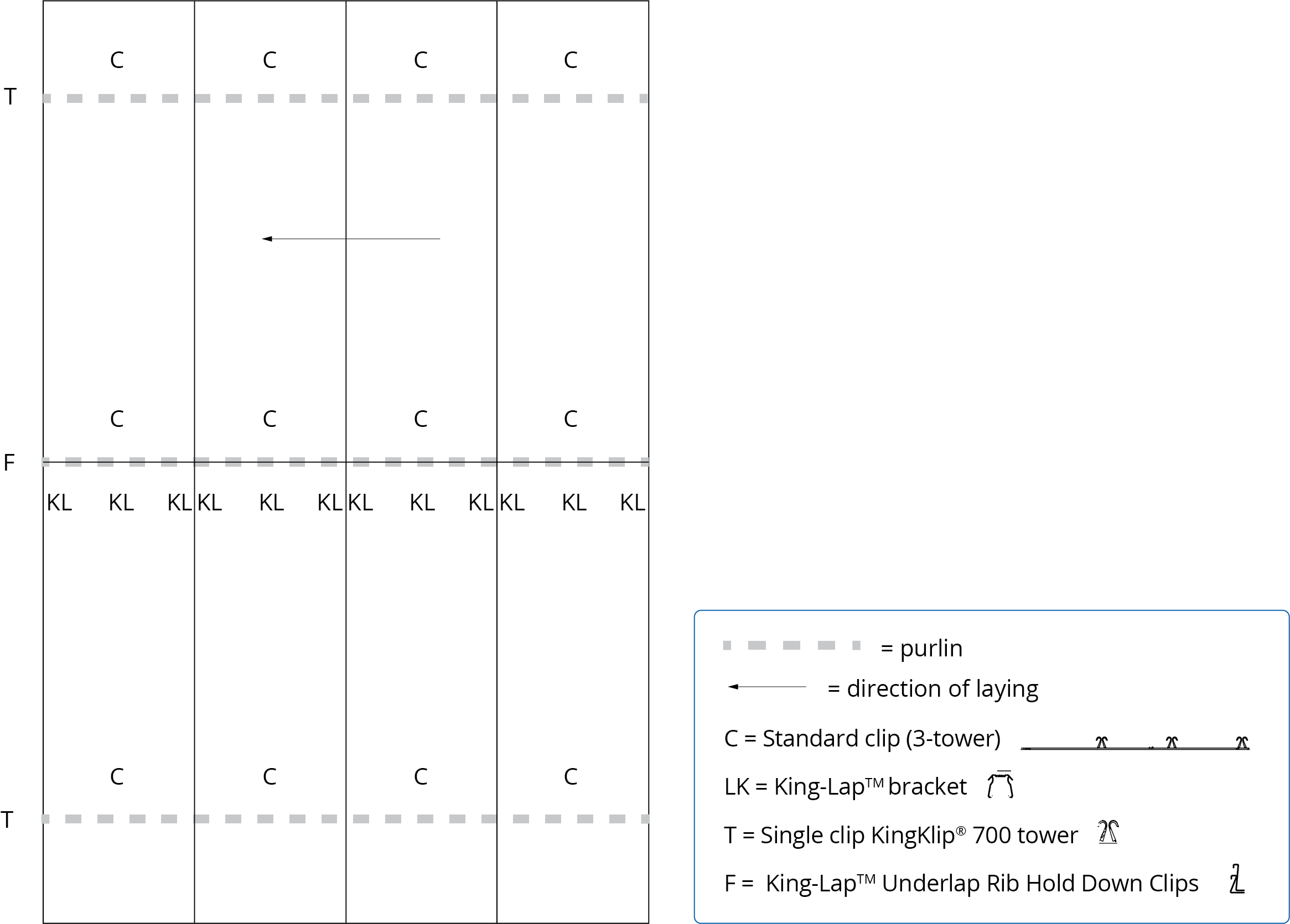
Figure 6: Layout of clips
King-Lap® assembly components
| King-Lap® assembly components | |
| King-Lap® brackets | 43 per 10m |
| Weather strip | 22 per 10m |
| King-Lap® Underlap Rib Hold Down Clips (F) for each finishing end of the King-Lap® joint | 1 |
Turning-down the upper sheet at the King-Lap™ end joint.
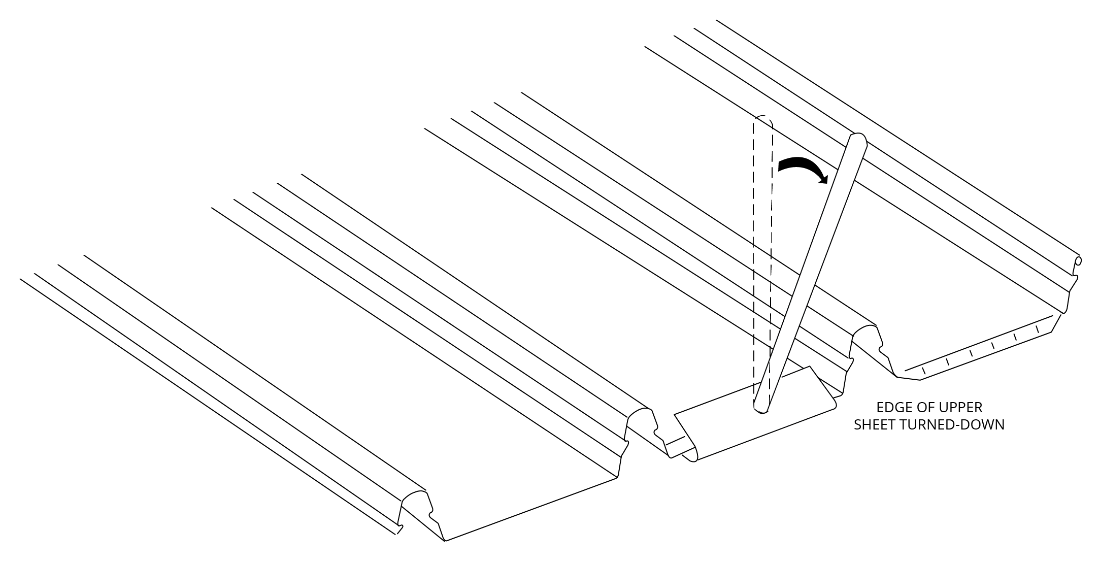
Figure 8
Laying sequence for KingKlip®700 end joint.
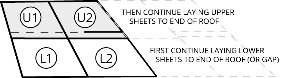
Figure 9
Step 1:
The installation of KingKlip®700 should generally be in accordance to the instructions given in the Fielders® Roofing and Walling Installation Manual.
Install the lower sheets of the KingKlip®700 prior to installing upper sheets as per the above sequence. The number of sheets laid will depend upon the site conditions and installer programme. Packers (10mm thick) may be required on the lowest purlin of the upper sheet for roofs of less than 2° slope and less than 1400mm span. For further information contact your nearest Fielders® Service Centre.
Step 2: Turn-up of pans
The pans on the upper end of the lower sheet are to be turned-up as detailed prior to fitting King-Lap™ brackets.
Place King-Lap™ brackets.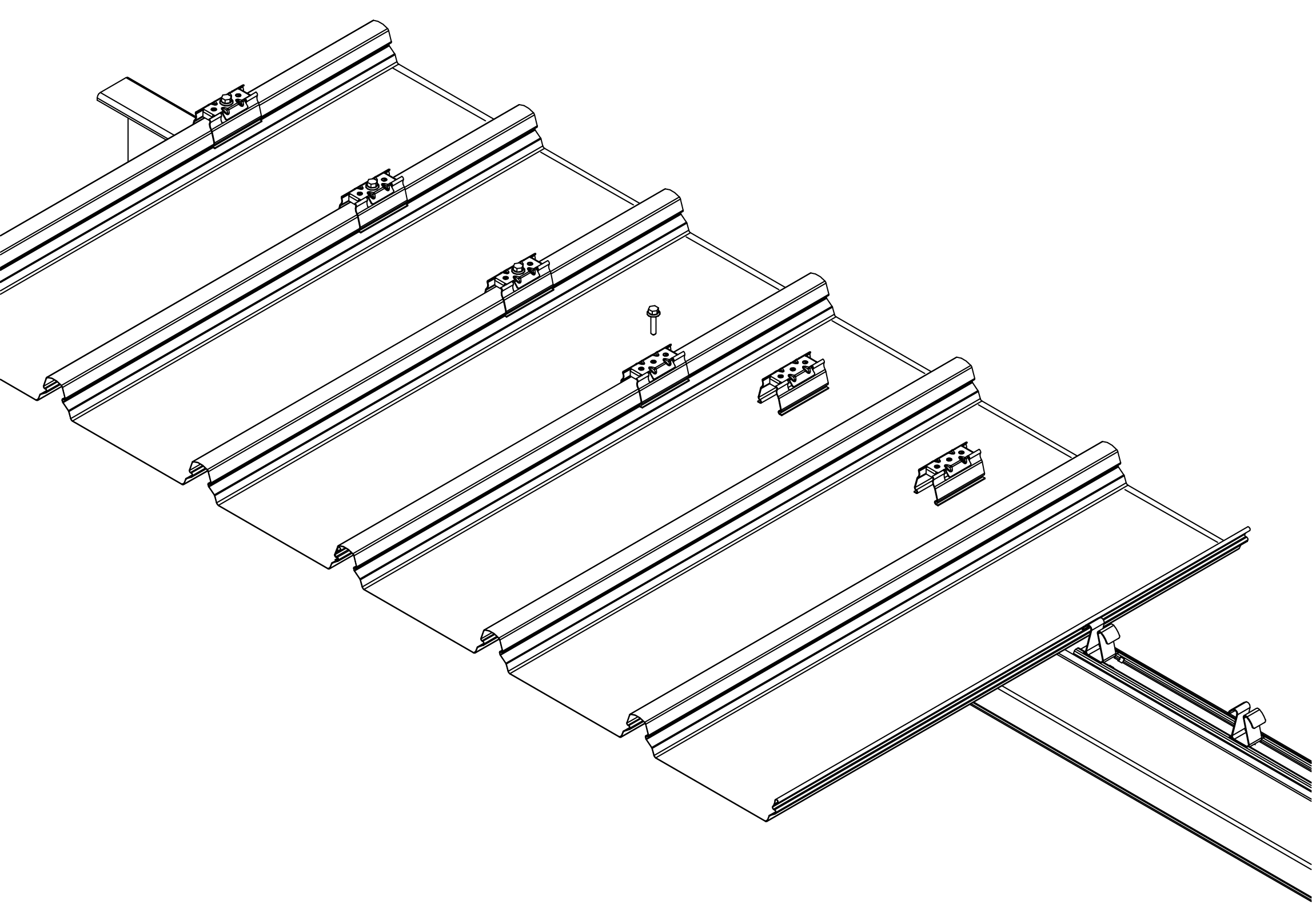
Figure 10
Step 3: Attach brackets to cladding
Once the required number of lower sheets are installed position the King-Lap™ brackets on the ribs and fix as detailed in Figures 1 and 5. Use a stringline or straight edge to ensure clips are aligned.
Lay King-Lap™ weather strip either side.
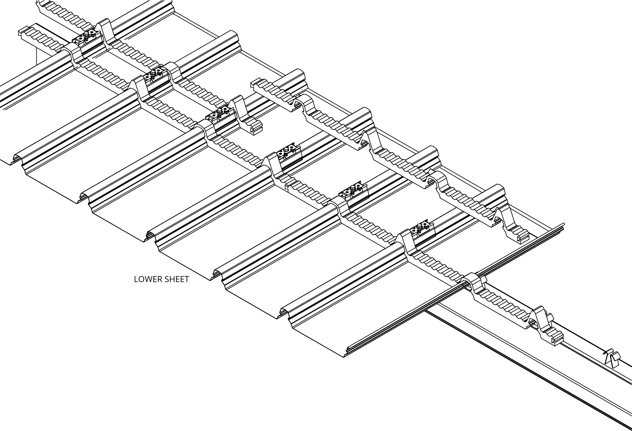
Figure 11
Turn-up of lower sheet of KingKlip®700 at King-Lap™ end joint.
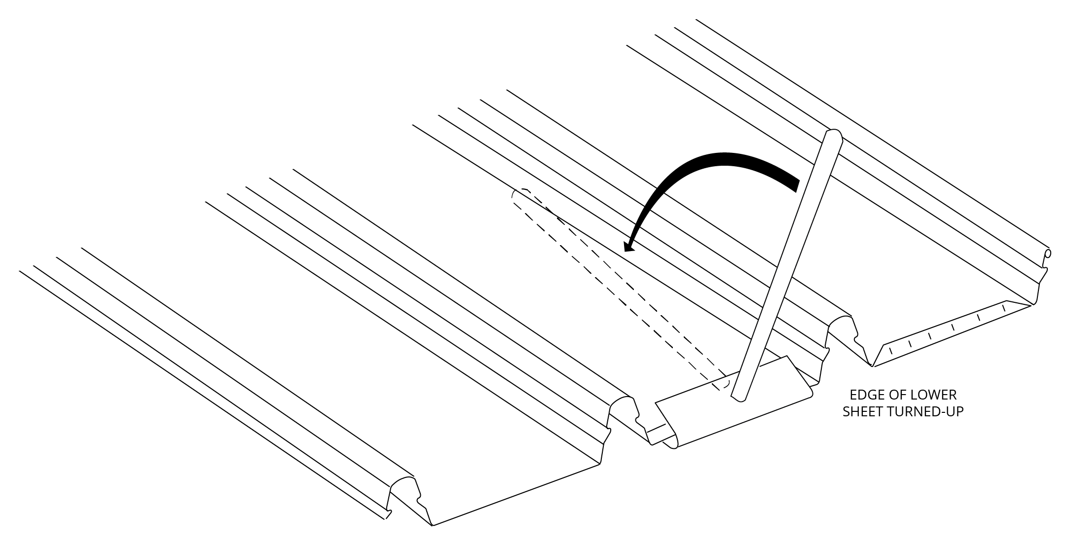
Figure 7
Step 4: Place weather strips
Interlocking weather strips are installed on top of cladding so they interlock to similar weather strips each side. The weather strips are placed on both sides and adjacent to the brackets.
The join on the weather strip should not be positioned adjacent to the male leg (underlap rib). Furthermore the two rows of weather strips must have the join in alternating pans (i.e. the joins are off-set).
Ensure the weather strips properly nest into the ‘S’ bends of the ribs and this allows for a staggered ventilation path.
Place upper sheet over King-Lap™ end joint.
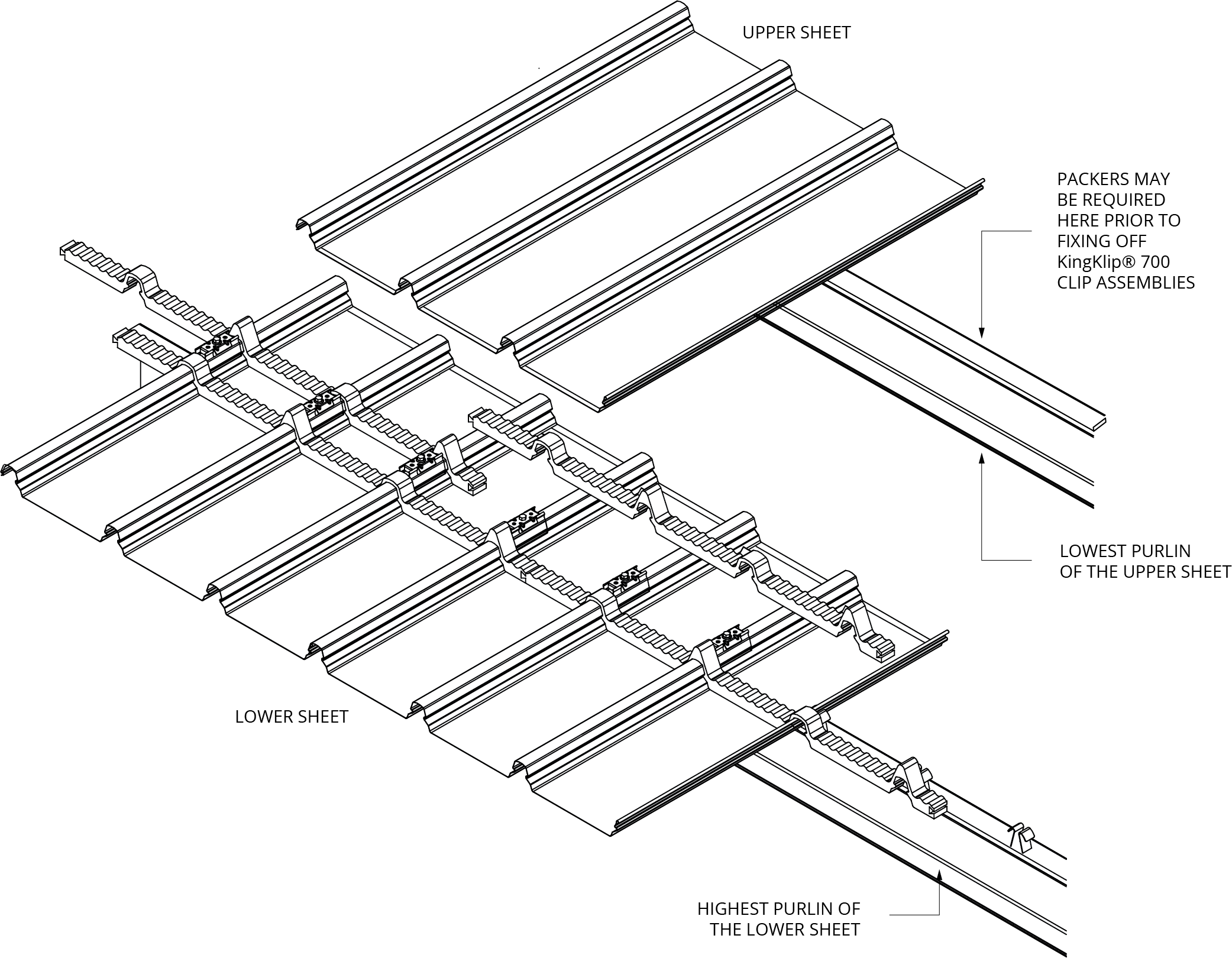
Figure 12
Step 5: Lay upper sheet over King-Lap™
Prepare the upper sheets by turning down the pans at the lower end of the sheet as detailed.
Position the upper sheets, taking care not to dislodge the previously installed weather strips.
While standing on the lower sheet, install the upper sheet onto the King-Lap™ brackets by first engaging the inner ribs and then the female side-lap rib (listen for the “snap” engagement). This engagement is done by foot pressure. Ensure correct engagement of the male leg onto the King-Lap™ bracket.
Install the remainder of the upper sheet onto the standard fixing clips using the standard process.
King-Lap™ Underlap Rib Hold Down Clips (F).
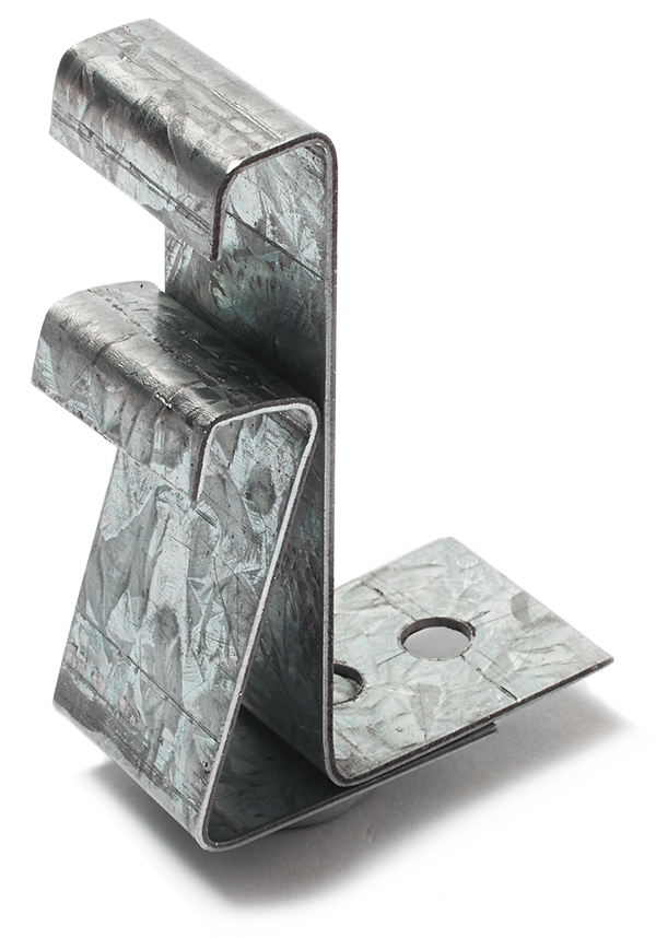
Figure 13
Step 6: Finishing
Continue the above process to the finishing edge/end of the roof. At the finishing edge of the roof, it is necessary to secure the two underlap ribs using Underlap Rib Hold Down Clips (F) screwed into position. The overhanging weather strips can be cut or torn off. It is now ready to receive barge flashing. Avoid walking at the roof edge.
Completed King-Lap™
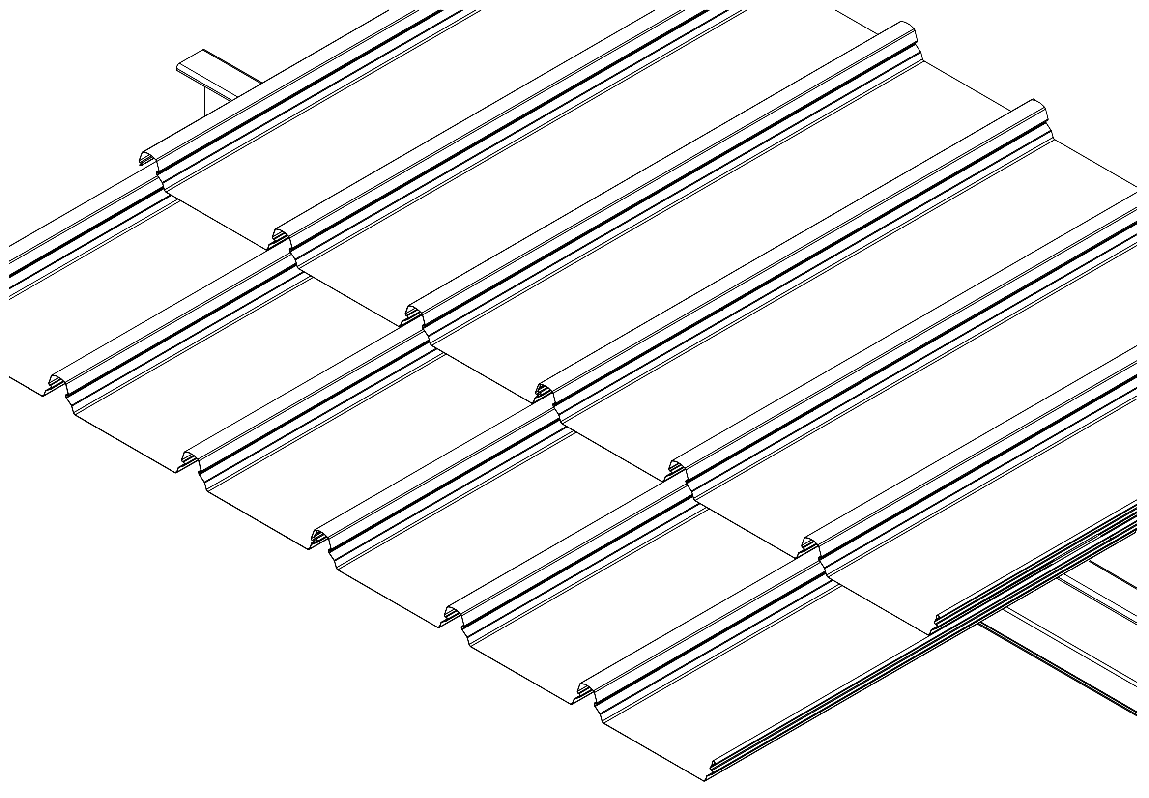
Figure 14
Figure KK NC 002 End Spans, Internal Spans and Overhangs
Figure KK MKII KingKlip® NY 001 - Concealed Fix Clipping System
Figure 1
Figure 2a: M1 Clip
Figure 2b: M2 Clip
Figure 3
Figure 4
Figure 5
Figure 6
Benefits of King-Lap™
- Low profile system maintains roof aesthetics with clean, long run roof lines for KingKlip® 700 cladding.
- Avoids step joins and purlin complexity to provide a cost effective way to achieve a long-length roofing design, even when using shorter roof sheets.
- Fast and easy to install – minimal change to current KingKlip® 700 installation practice.
- Tested and proven in our NATA-accredited testing facility. If installed correctly, will preserve all existing roofing warranties and capacities.
- Safe and effective weather resistant seal.
- Suitable for cyclonic applications.
- Readily allows for thermal movement of roof sheets.
- As a stand alone solution, compatible with translucent sheeting.
King-Lap™ is comprised of brackets which are fixed to the ribs and two separate weather strips.
Figure 1
Background on thermal expansion
All metals expand and contract with changes in temperature. Although steel is by far the least affected of all the metals commonly used for roof and wall cladding, the changes in length experienced in very long runs of roofing are significant.
When a King-Lap™ is used, the length of each individual sheet is necessarily shorter, thus reducing the impact of thermal movement.
King-Lap™ is an expansion joint/lap joint hybrid
An expansion joint involves overlapping the ends of the upper sheets over the ends of the lower sheets. With King-Lap™, no extra purlin is needed at the joint.
A weather strip provides protection from wind-blown rain and is made from closed cell polyethylene foam. It is used between the upper and lower sheets and laid in pairs, one either side of the King-Lap™ bracket to provide a weather resistant barrier from wind driven rainwater. It also provides air flow to reduce likelihood of condensate build-up.
The King-Lap™ bracket is a pressed metal component that saddles the rib of the KingKlip®700 roofing by engaging the “S” bends of the lower sheet and is clipped into place. The bracket is fixed to the lower sheet by fasteners through the pre-punched holes however this allows the upper sheet to move relative to the bracket due to thermal expansion.
Testing
Made from Australian-made G550 AZ150 ZINCALUME® steel, King-Lap™ is strong. King-Lap™ has been tested for performance in wind uplift and weather-resistance at Fielders® NATA-accredited materials science testing laboratory. This means you can be confident that King-Lap™ will perform to specification when installed according to our design limitations and installation guidelines.
Wind uplift tests were performed to ensure King-Lap™ clips met the performance standards required.
Figure 2
Weather test rig is used to test weather-resistance by blowing simulated wind borne rain.
Figure 3
King-Lap™ joint layout and fixing
This will allow normal concealed fastening at the support and thus allowing thermal movement to occur at the King-Lap™. To install the King-Lap™ bracket, locate each King-Lap™ bracket as per Figure 5, then hand press to snap fit each King-Lap™ bracket to the KingKlip®700 (Figure 4a, 4b). For non-cyclonic areas, using a low torque setting on the drill to ensure the cladding is not stripped, secure through the top hole of the King-Lap™ and also through the crest of the lower sheet (Figure 4a). For cyclonic areas, use two fasteners by fixing through the sides of the King-Lap™ bracket into the sides of the rib (Figure 4b).
Weather strips are laid either side of the King-Lap™ brackets and offset (see installation steps).
Figure 4
Fixing of King-Lap™ brackets to cladding.
Figure 4a
Fixing of King-Lap™ brackets to cladding.
Figure 4b
Details of King-Lap™ at support.
Figure 5
NOTE: The installer must make allowance for added sheet length for upper and lower sheets or any intermediate sheet resulting from multiple joints to construct the joint.
When specifying or ordering, please refer to the layout schematic detailed below.
This layout shows the location and types of clips/brackets required to fit a KingKlip®700 using King-Lap™ end joint.
Figure 6: Layout of clips
King-Lap® assembly components
| King-Lap® assembly components | |
| King-Lap® brackets | 43 per 10m |
| Weather strip | 22 per 10m |
| King-Lap® Underlap Rib Hold Down Clips (F) for each finishing end of the King-Lap® joint | 1 |
Turning-down the upper sheet at the King-Lap™ end joint.
Figure 8
Laying sequence for KingKlip®700 end joint.
Figure 9
Step 1:
The installation of KingKlip®700 should generally be in accordance to the instructions given in the Fielders® Roofing and Walling Installation Manual.
Install the lower sheets of the KingKlip®700 prior to installing upper sheets as per the above sequence. The number of sheets laid will depend upon the site conditions and installer programme. Packers (10mm thick) may be required on the lowest purlin of the upper sheet for roofs of less than 2° slope and less than 1400mm span. For further information contact your nearest Fielders® Service Centre.
Step 2: Turn-up of pans
The pans on the upper end of the lower sheet are to be turned-up as detailed prior to fitting King-Lap™ brackets.
Place King-Lap™ brackets.
Figure 10
Step 3: Attach brackets to cladding
Once the required number of lower sheets are installed position the King-Lap™ brackets on the ribs and fix as detailed in Figures 1 and 5. Use a stringline or straight edge to ensure clips are aligned.
Lay King-Lap™ weather strip either side.
Figure 11
Turn-up of lower sheet of KingKlip®700 at King-Lap™ end joint.
Figure 7
Step 4: Place weather strips
Interlocking weather strips are installed on top of cladding so they interlock to similar weather strips each side. The weather strips are placed on both sides and adjacent to the brackets.
The join on the weather strip should not be positioned adjacent to the male leg (underlap rib). Furthermore the two rows of weather strips must have the join in alternating pans (i.e. the joins are off-set).
Ensure the weather strips properly nest into the ‘S’ bends of the ribs and this allows for a staggered ventilation path.
Place upper sheet over King-Lap™ end joint.
Figure 12
Step 5: Lay upper sheet over King-Lap™
Prepare the upper sheets by turning down the pans at the lower end of the sheet as detailed.
Position the upper sheets, taking care not to dislodge the previously installed weather strips.
While standing on the lower sheet, install the upper sheet onto the King-Lap™ brackets by first engaging the inner ribs and then the female side-lap rib (listen for the “snap” engagement). This engagement is done by foot pressure. Ensure correct engagement of the male leg onto the King-Lap™ bracket.
Install the remainder of the upper sheet onto the standard fixing clips using the standard process.
King-Lap™ Underlap Rib Hold Down Clips (F).
Figure 13
Step 6: Finishing
Continue the above process to the finishing edge/end of the roof. At the finishing edge of the roof, it is necessary to secure the two underlap ribs using Underlap Rib Hold Down Clips (F) screwed into position. The overhanging weather strips can be cut or torn off. It is now ready to receive barge flashing. Avoid walking at the roof edge.
Completed King-Lap™
Figure 14

Figure KK NC 002 Roofing and Walling: End Spans, Internal Spans and Overhangs
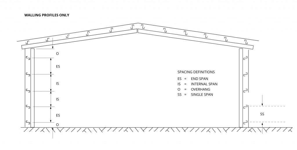 Figure KK NC 003 Walling only: End Spans, Internal Spans and Overhangs
KingKlip® 700 WA Non cyclonic S-Clip Concealed Fix Clip System
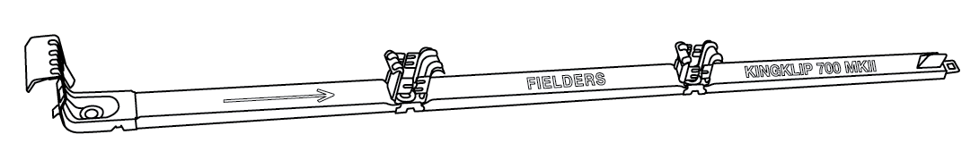
Figure KK MKIII KingKlip® NC 001 - Concealed Fix Clipping System

Figure 1

Figure 2

Figure 3
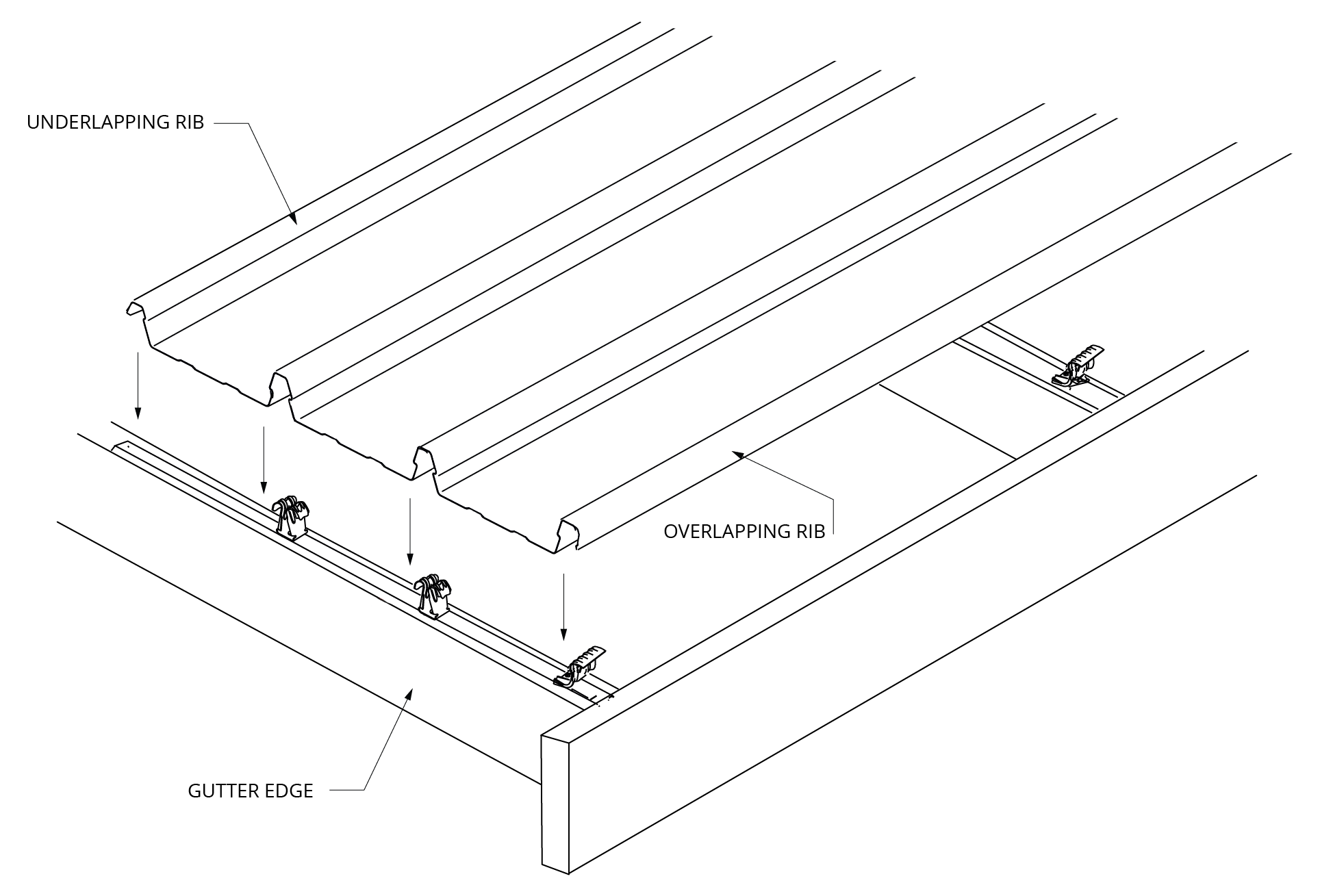
Figure 4a
Figure 4b
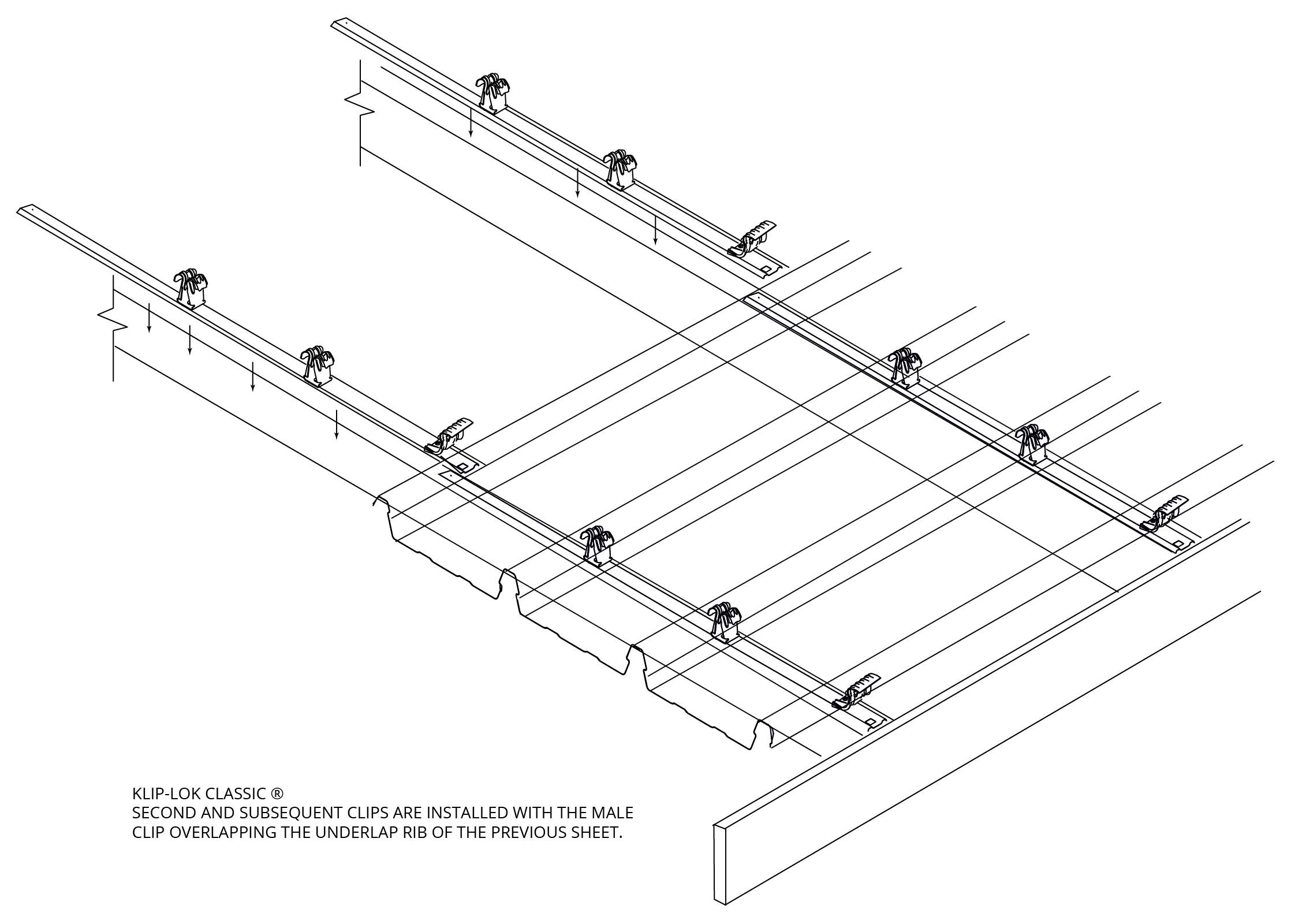
Figure 5
Figure 6
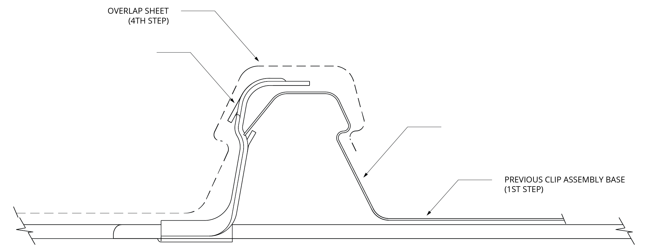
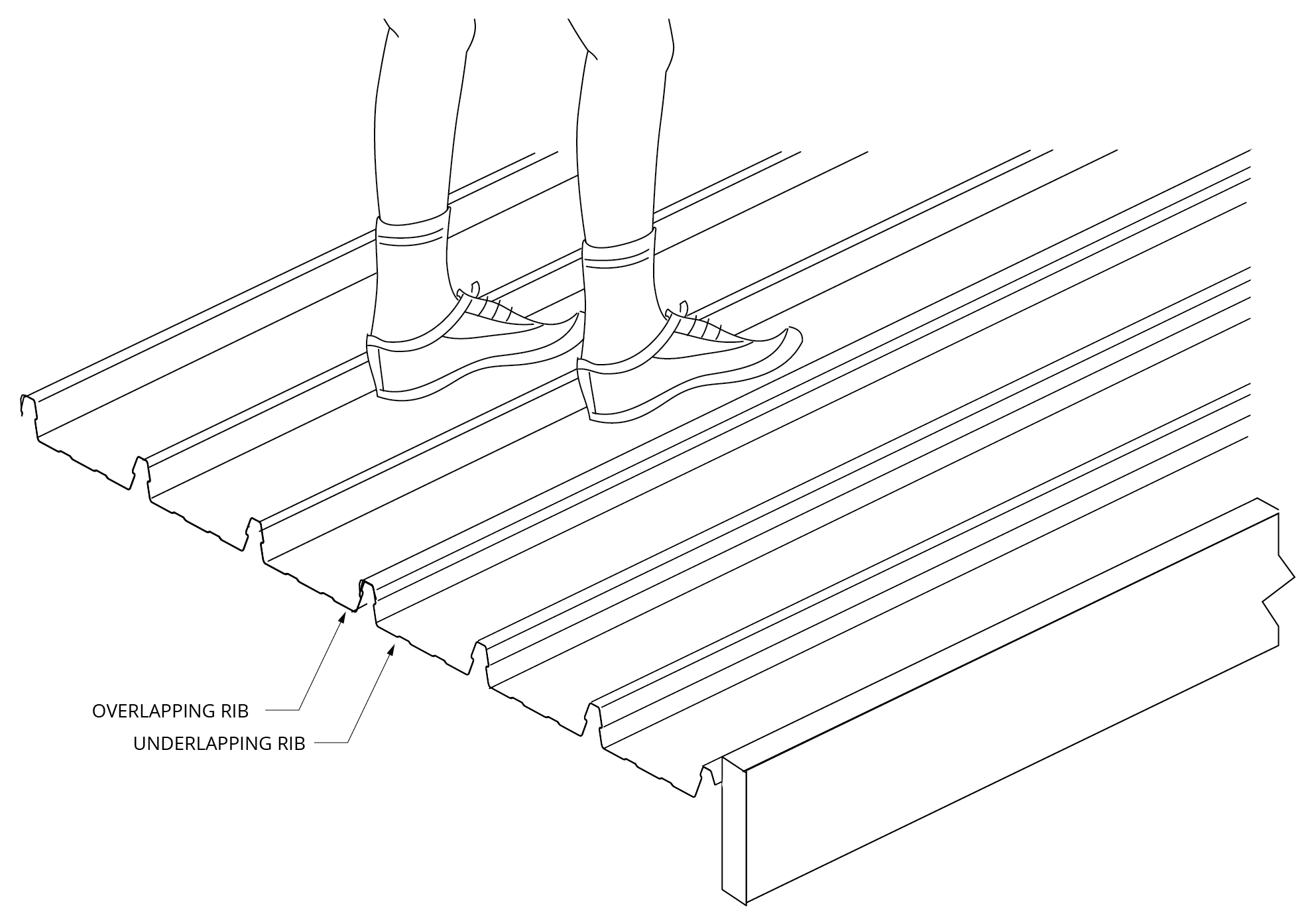
Figure 7
Figure 8
Box Gutter

Figure KK NC 002 Roofing and Walling: End Spans, Internal Spans and Overhangs
Figure KK NC 003 Walling only: End Spans, Internal Spans and Overhangs
KingKlip® 700 WA Non cyclonic S-Clip Concealed Fix Clip System
Figure KK MKIII KingKlip® NC 001 - Concealed Fix Clipping System
Figure 1
Figure 2
Figure 3
Figure 4a
Figure 4b
Figure 5
Figure 6
Figure 7
Figure 8
Box Gutter