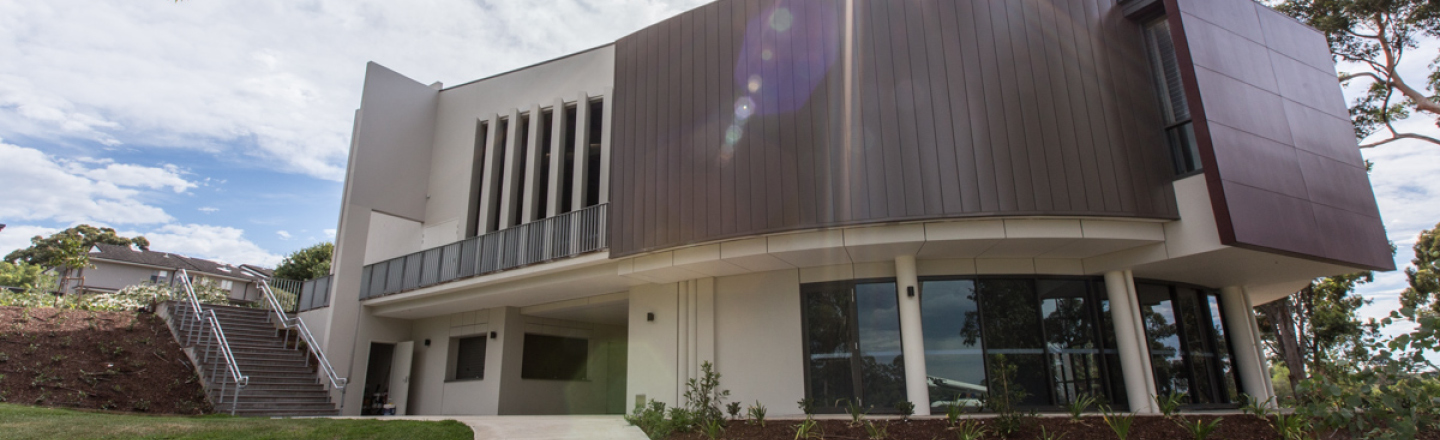
About Boulevard™
Where a flat recessed joint look is wanted without compromising the quality of the materials, Fielders® Boulevard™ is the solution. A contemporary wall cladding, Boulevard™, is available in a wide array of colours and finishes and is the most versatile in the Finesse® range. It offers sophisticated European technologies combined with Fielders® local know-how to deliver a high end look to any project.
Boulevard™ is a pierced-fixed wall cladding system installed with a ventilated air space. It involves laying interlocking panels on a metal framework fixed to the supporting structure. The panels are simply connected by the use of an interlocking groove giving the elegant appearance of a recessed joint.
Boulevard™ can be laid vertically or horizontally. The choice of direction implies different aesthetics and technical solutions for the main flashings. Panels are fixed directly on plywood or steel battens.
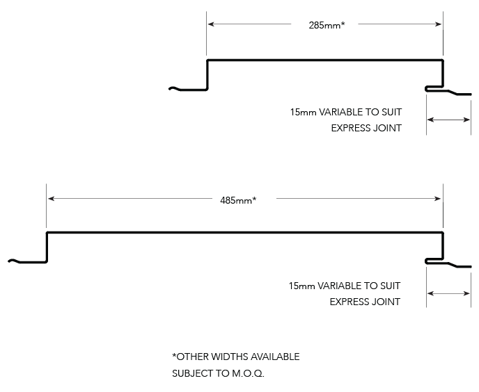
Boulevard™ is available in two standard widths 285mm and 485mm, all with a side depth of 22mm. The panel comes in lengths from 0.5m to 8.0m, with a width of longitudinal joint of 5mm to 18mm, with 15mm being the standard.

Material Specifications
| Property | 285mm Pan Width | 485mm Pan Width | Notes | |||||
| Base Metal Thickness (mm) | 0.55 | 0.70 | 0.75 | 0.55 | 0.70 | 0.75 | BMT | |
| Total Coated Thickness (mm) | 0.60* | 0.75* | 0.80* | 0.60* | 0.75* | 0.80* | TCT | |
| Mass / Unit Length | ZINCALUME® | 1.76 | 2.25 | 2.23 | 2.65 | N/A | 3.36 | kg/m |
| COLORBOND® | 1.78* | 2.29 | 2.24* | 2.67* | 3.37* | |||
| Mass / Unit Area | ZINCALUME® | 5.94 | 7.51 | 8.03 | 5.34 | N/A | 7.23 | kg/m2 |
| COLORBOND® | 6.07* | 7.64 | 8.17* | 5.47* | 7.35* | |||
| Nominal Panel Width (mm) | 280 | mm | ||||||
| Maximum Purlin / Girt Spacing (mm) | 600 | |||||||
| Minimum Yield Strength (MPa) | G300 | |||||||
| Coating Class | AM100 - COLORBOND® Steel AM100 - COLORBOND® Metallic AM125 - ZINCALUME® AM150 - COLORBOND® Ultra Steel | Minimum Coating g/m2 of Zinc - Aluminium |
||||||
| Tolerance | Sheet length ±3mm Cover width ±2mm |
|||||||
| Thermal Expansion | 2.9mm average per 5.0 metre @ 50˚C change |
|||||||
Notes:
- 0.75mm is available subject to minimum order quantities.
- The COLORBOND®; and ZINCALUME® material is in accordance to AS 1397, AS 1365 and AS 2728. The installation of the cladding should be in accordance to AS 1562.1 and HB39.
- *is based on standard COLORBOND®; single-sided material. For other painted steel options please contact a Fielders® representative.
Cyclonic Testing
Fielders® have undertaken cyclonic testing of the Boulevard™ profile in a 285mm panel width for walling applications in accordance with the loading sequence in AS4040.3 2018 for wall cladding systems. Design data provided for Boulevard™ is based on the following Australian Standards:
- AS 1170.2:2011 Structural design actions Part 2: Wind actions
- AS 1562.1-2018 Design and installation of sheet roof and wall cladding Part 1: Metal
- AS4040.0-1992 (R2016) Methods of testing sheet roof and wall cladding Part 0: Introduction, list of methods and general requirements
- AS4040.1-1992 (R2016) Methods of testing sheet roof and wall cladding Method 1: Resistance concentrated loads
- AS4040.2-1992 Methods of testing sheet roof and wall cladding Method 2: Resistance to wind pressures for non-cyclone regions
- AS4040.3 2018 Methods of testing sheet roof and wall cladding Method 3: Resistance to wind pressures for cyclone regions
- AS4055:2012 Wind Loads for Housing
- SA HB 39: 2015 Handbook - Installation code for metal roof and wall cladding National Construction Code of Australia
Boulevard™ can be supported on one of three supporting structures; plywood, steel battens or Fielders® KingFlor® KF40®. The cyclonic wind load capacities are shown in Table BL WC CY 001.
Cyclonic Impact Resistance from Wind-Borne Debris
Parts of a building envelope (cladding, doors, windows) may be required to resist windborne debris according to AS/NZS 1170.2: 2011 and Technical Note No. 4, ‘Simulated windborne debris impact testing of building envelope components’, Cyclone Testing Station, James Cook University. These standards specify debris impact loading by timber member of 4kg mass with nominal cross-section of 100mm x 50mm and 8mm diameter spherical steel balls. BOULEVARD™ (walling) cyclonic assemblies have been evaluated to effectively resist cyclonic wind-borne debris for wind region C and D when used in conjunction with plywood or KF40® backing for walling applications. Please refer to the relevant fixing requirements for BOULEVARD™.
Limit State Wind Pressure Capacities (kPa)
| Cover Width (mm) | CkD Structural Plywood | Steel Batten | KF40® |
| 285 | 8.00 | 4.05 | 10.5 |
Notes:
- 1. Support and fastener spacings as detailed in figures BL ID CY 001-003.
- 2. Capacities have been derived from testing based on the following criteria:
- 3. CKD Structural plywood to be supported at max. 600mm centres
- 15mm thick for pressure requirements - walling applications
- 19mm thick for debris impact requirements - walling applications
- 4. 40mm steel battens shall be a minimum of 0.75mm BMT G550 steel with a maximum of batten space of 450mm c/c and a maximum batten span of 1.2m. Battens to be fixed to minimum of 1.5mm BMT G550 steel supports
- 5. KF40® shall be minimum of 0.75mm BMT and supported at a maximum of 1.2m c/c to minimum 1.5mm BMT G550 steel supports.
Installation Layout
Plywood
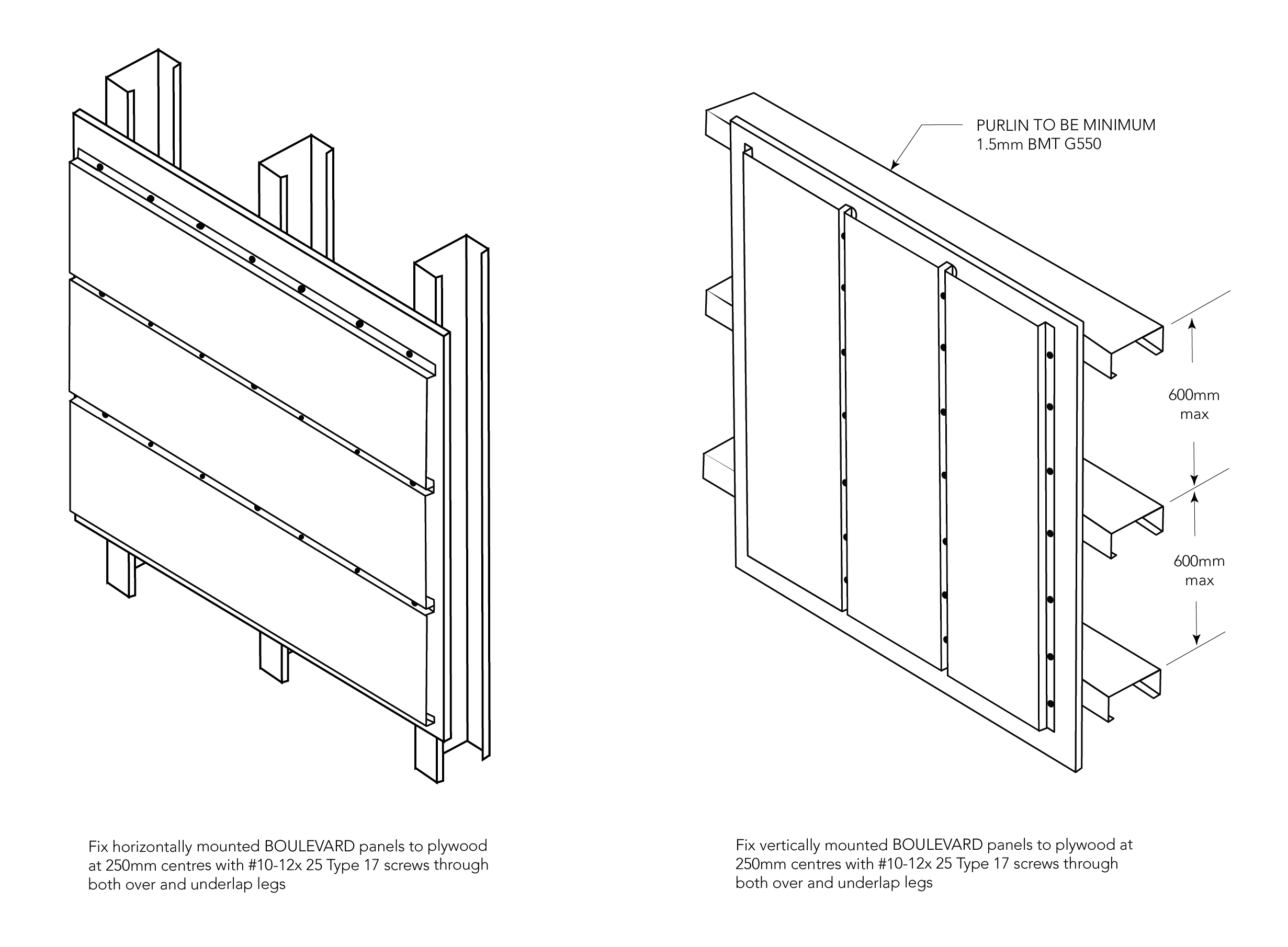
Figure BL ID CY 001
Steel Batten
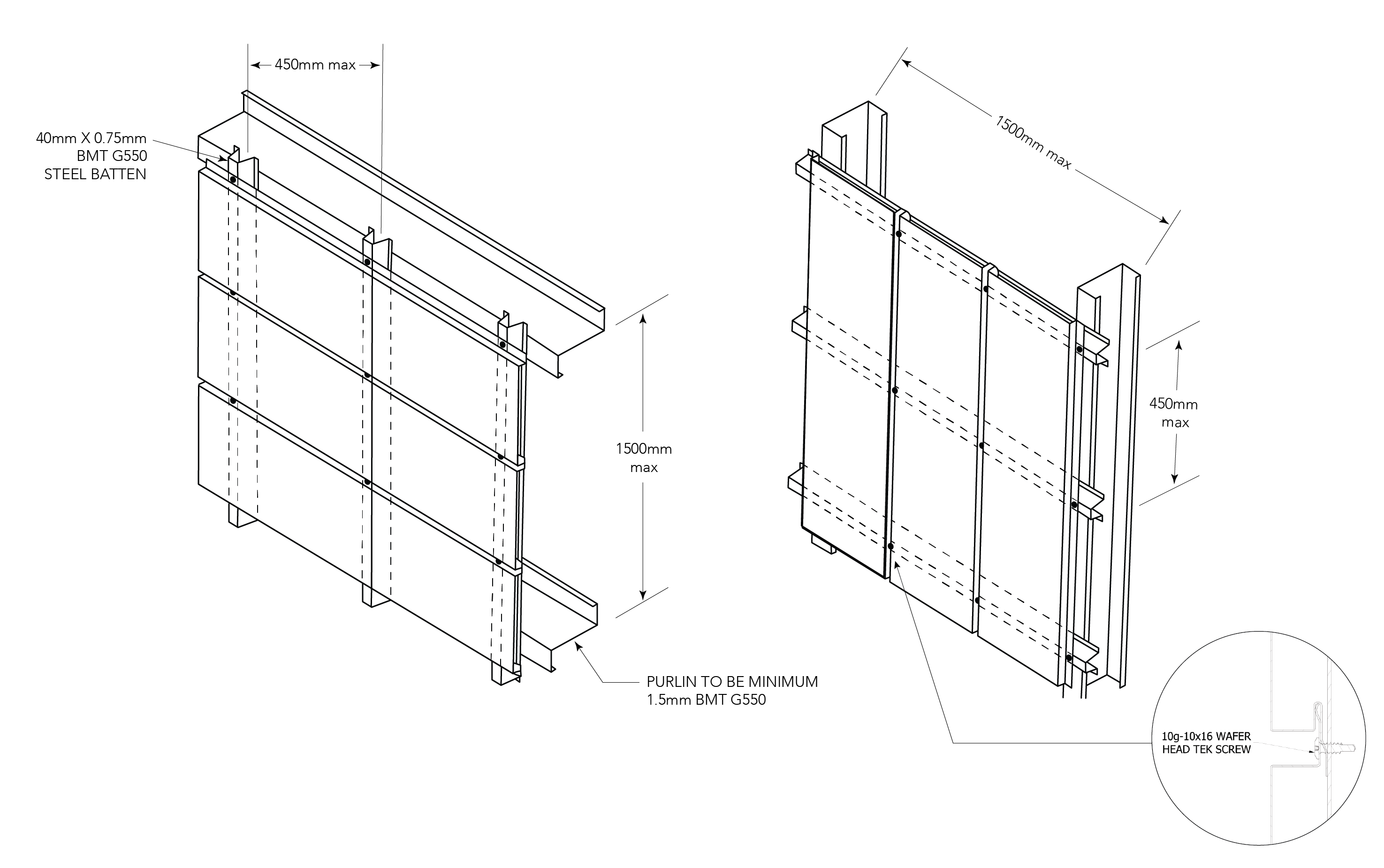
Figure BL ID CY 002
KingFlor® KF40®
Where resistance to wind-borne debris is required, as per AS/NZS 1170.2: 2011, KF40 backing is required as per the following details:

Figure BL ID CY 003
Installation Guide
Boulevard™ provides a water screen only and needs to be fitted on a water tight barrier. This may consist of a precast wall or steel sheeting backing, such as Panelform™, or another waterproof membrane like heavy duty roof sarking. Prior to commencement ensure the surface that the system is being fixed to is free of sharp edges and in the correct plane.
If the membrane is to be fixed before the 40mm batten use the following procedures. It is recommended that the membrane be Panelform™ as this will allow the membrane to be made watertight without the chance of movement and vibration.
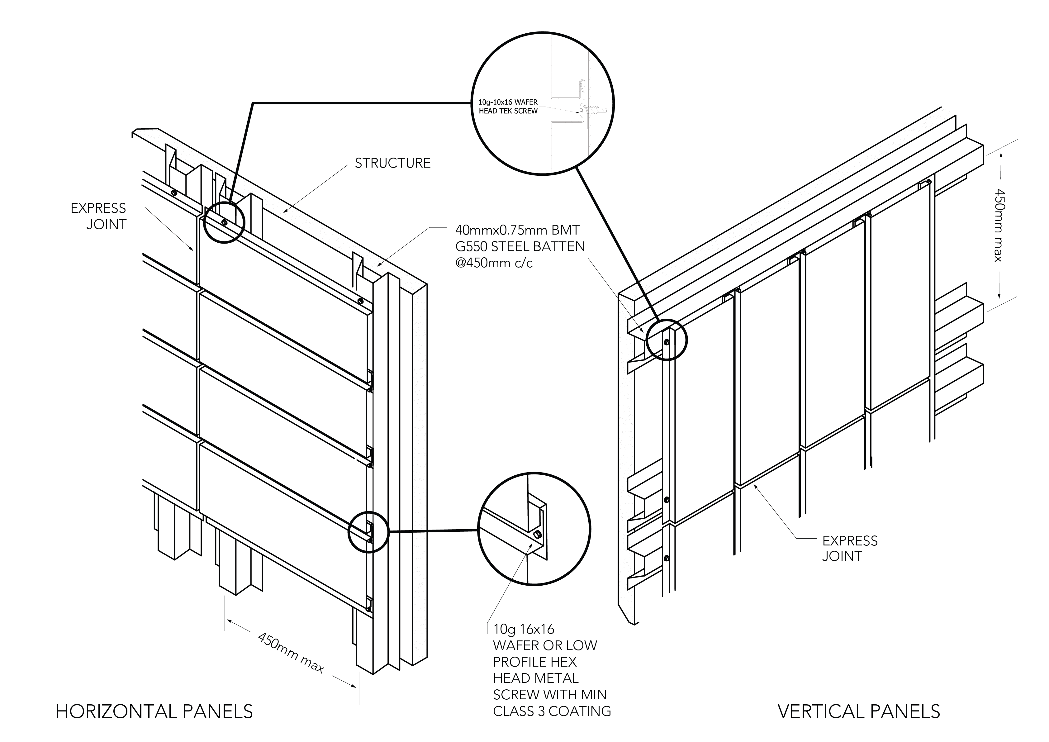
Figure BL ID CY 004
Fixing of the Membrane
(Sisalation with insulation sarking attached)*
-
Check that the steel work or concrete is free of any sharp edges or protrusions that may puncture the membrane.
-
The sarking must be a minimum of 453 Sisalation or equivalent with the Sisalation to the outside face.
-
The sarking must be hung and sealed at the top. It must be free of ripples and puckers with holding battens between the 40mm vertical battens securing it to the supporting member. See BL ID CY 011.
-
All laps in the sarking must be made with 150mm lap sealed with double sided tape between the faces of the foil and taped with sisal tape on the outside face.
-
The perimeter of the membrane (blanket) must be sealed also with premium quality Sisal tape with holding or 40mm battens to secure it. See BL ID CY 014.
Note: - It is essential that attention is paid to ensuring that sarking is air tight, fixed in a way that it won’t flap or tear away at the laps or edges. -
At the bottom of the façade a flashing is required to direct any water from the blanket membrane external of the façade. This will be done in a way as to allow any water to pass between the flashing and the foot mould. See BL ID CY 012.
-
If any of the membrane is to be fixed horizontally a different fixing procedure is to be followed; please contact your local Fielders® Representative.
Fixing of the Backing Plates
-
The backing plates should be full length where possible and fixed with Teks with a Neo washer or a 3mm pop rivet at a maximum of 1200mm centers.
-
If pop rivets are used they should be sealed rivets or sealed with silicone.
-
Any laps should be a minimum of 100mm.
-
The top of all backing plates should have a return 10mm fold to prevent water from being blown over the end of the plate. See BL ID CY 015.
-
Backing plates for Express joints should be 100mm wide overall with 10mm return fold on both sides if the Express joint is 15mm wide. See BL ID CY 007.
Fixing of the 40mm Battens
-
The battens should be fixed on both sides with 10g-16x16mm Hex Head Tek Screws to the girts through the membrane. See BL ID CY 007 and BL ID CY 008. If an insulation blanket is fitted the screws should be 10g-16x25mm Hex Head Tek Screws.
-
If fixed to a concrete wall the fixing centers of the battens should be a maximum of 450mm apart.
-
All vertical 40mm battens should be fixed at a maximum of 450mm apart.
-
All battens fixed to support vertical joints, external and internal corners should be positioned so that the return edge of the backing plate is center of the face of the batten. See BL ID CY 007 and BL ID CY 008. This allows the fastener fixing the panel to be fixed in a location that doesn’t penetrate the backing plate.
Note:
Care should be taken not to puncture the membrane while fixing the 40mm battens. If it is punctured it should be taped on both sides of the puncture.
Fixing of the Panels (Horizontal)
-
1. The top mould of parapet cap should be fixed first with the female edge downward. See BL ID CY 011.
-
The panels should have a foam block both ends fixed 25mm inside the stop end of the panel with the center of the foam block center to the 10mm return fold on the side of the backing plate. See BL ID CY 007, BL ID CY 008, BL ID CY 015.
-
A small corner should be removed off the bottom of the foam block to allow water or condensation to drain out freely. See BL ID CY 015.
-
This is required on straight panels and internal corners but not on external corners.
-
Measure out a matrix and mark the steel battens for the full length with the width of the panel plus gap so that when the panels are placed in position the bottom edge of the female rib can be lined up to the marks. This will ensure that the panels are fixed parallel with the same gap along the complete face. See BL ID CY 017.
-
Before installing a panel, a silicone bead must be applied to the back of the male and female edges from the center of the foam block to the edge of the panel. See BL ID CY 015.
-
The male edge of the panel is then inserted into the female edge leaving a gap that is predetermined, lining up the bottom edge of the panel with the mark on the hat section. See BL ID CY 012 and BL ID CY 016.
-
Screw the trailing female edge to the hat section with 10g-16x16mm Wafer Head Tek Screws.
-
Continue to fix all the panels until the bottom of the façade is reached.
-
When all sections of the façade are complete the foot mould is then fitted with the top vertical edge engaging the female recess on the panel. The predetermined gap between the panels should be maintained between the foot mould and the bottom panel.
-
The foot mould must be fitted in a way to allow water to drain between the foot mould and the flashing at the bottom of the membrane.
-
If the top of the façade has a fall (not horizontal), cut and fold the panels as in BL ID CY 009.
-
When the side of a façade finishes against a brick or concrete wall it should be done as per BL ID CY 014.
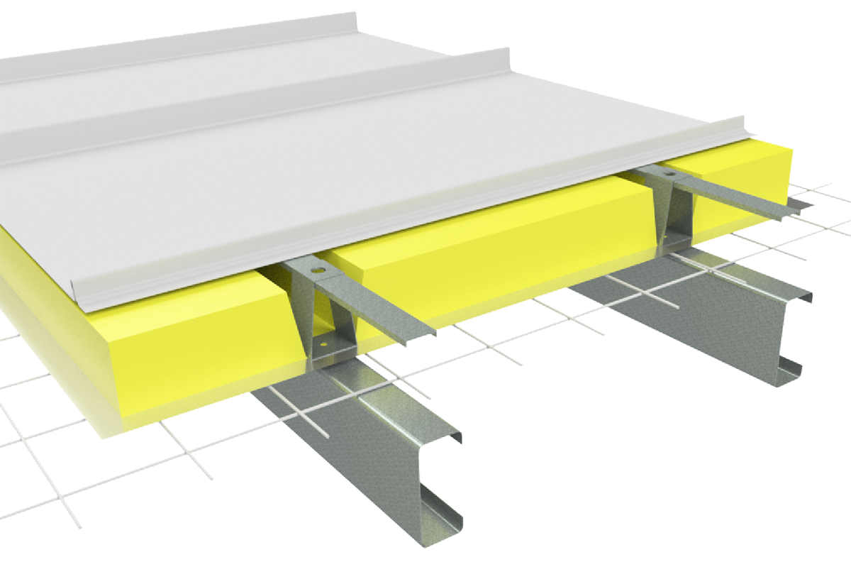
Insulation
Care needs to be taken when installing insulation with Boulevard™ roof sheeting. When insulation thicknesses up to 50mm are installed the screws may need to be increased depending on the thickness and density of the insulation. When the screw is properly tightened into metal there should be a minimum of three (3) threads protruding past the support being fixed in to. For timber, the screw must have a minimum embedment of 25mm into timber.
When insulation is required in conjunction with Finesse® profiles, Fielders® recommend the use of a thermal spacer to help maintain Rw values as well as minimising any bulging in the profile caused by the insulation.
Insulation blankets and batts can cause wide flat pan cladding to bow out between the supports, between fasteners along the support, or bow the pans. For insulation blankets and batts as well as more dense glass wool and rock wool, and thicker insulation, spacers are recommended.
BL INS CY 001
Note:
Image displayed using Shadowline profile
Recommended Fasteners
| Supports | Recommended Fastener (without insulation) |
| Steel 1.5mm | 10g-16x16mm Wafer or low profile Hex Head Tek Screw with a minimum class 3 of coating |
| Plywood | 10g-16x25mm Wafer or low profile Hex Head Type 17 Screw with a minimum class 3 of coating |
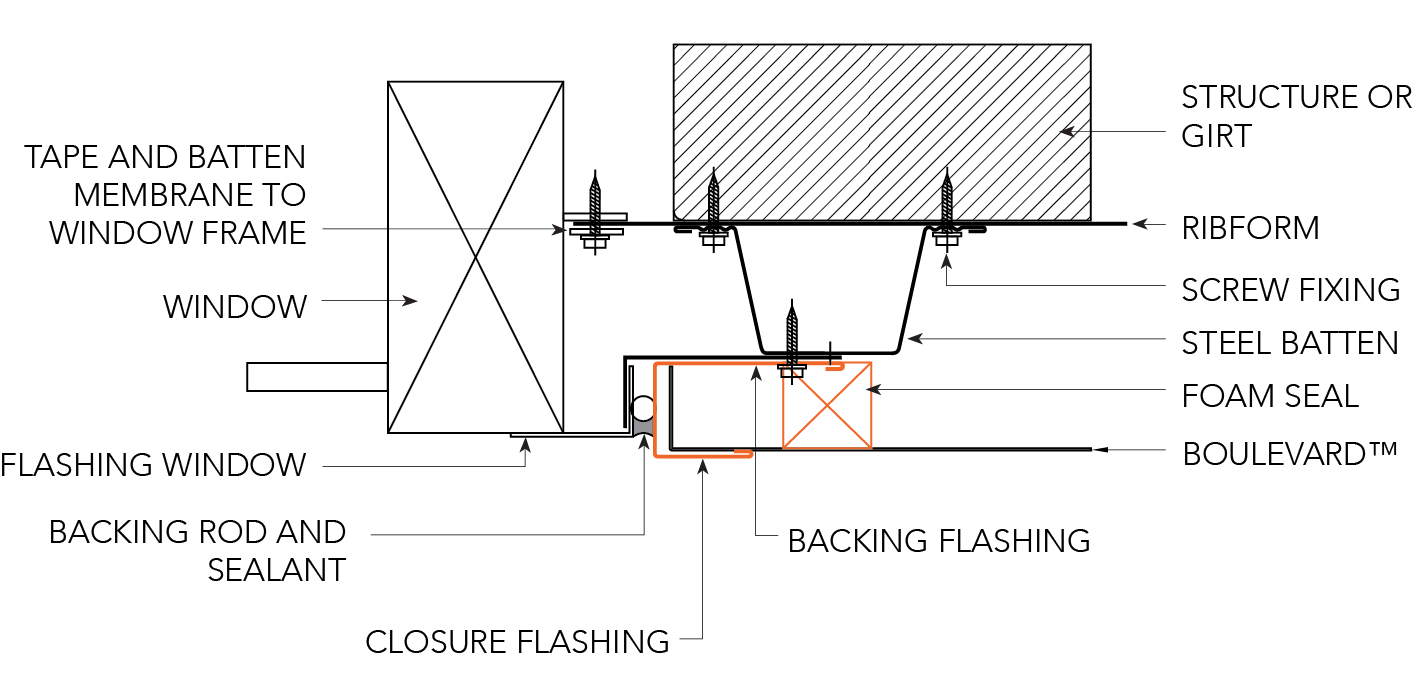
Fixing of Windows and Doorways
-
When fixing the windows & doorways (penetrations) remember that the panels are the waterproof seal and the membrane is the air seal and backup water seal.
-
The membrane must be sealed to the penetrations in a way that it can’t over time break away. This may require the fitting of a holding batten. It also must be draining to the outside of the building.
-
The panels over the penetrations must be flashed to the penetration allowing any water that drains from the membrane to escape between the flashing and the top of the penetration.
-
BL ID CY 010-016 show some typical details to the top, bottom and sides of window penetrations.
Note:
Boulevard™ creates a water screen and not a watertight barrier. If a watertight barrier is required it is recommended that an additional cladding layer is included behind the Boulevard™ such as Panelform™. For further information contact Fielders®.
Oil Canning
Oil canning is a characteristic of thin gauge cold formed metal products which is caused by the internal stresses with the metal. There are many factors that influence the degree of oil canning.
For further information about Oil Canning, please refer to our Oil Canning reference page.
Installation Details
Standard Fixing Detail
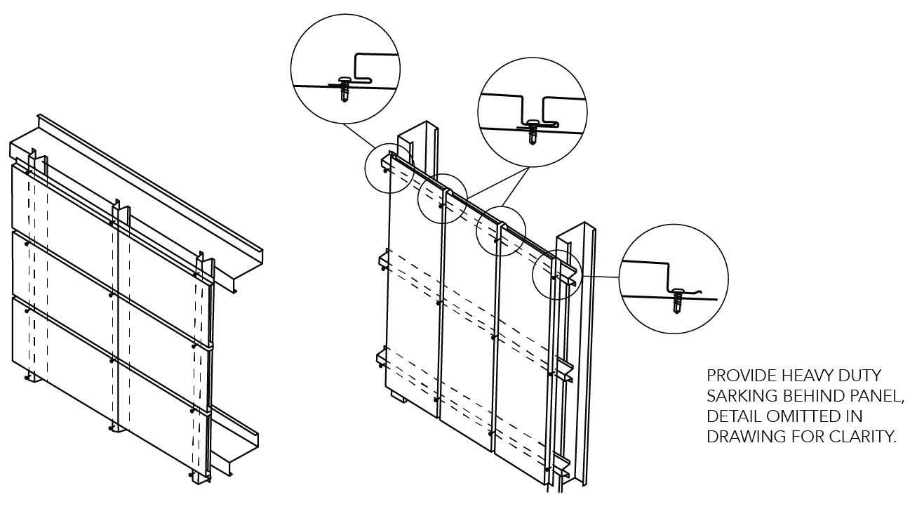
Figure BL ID CY 005
Express Joint Detail
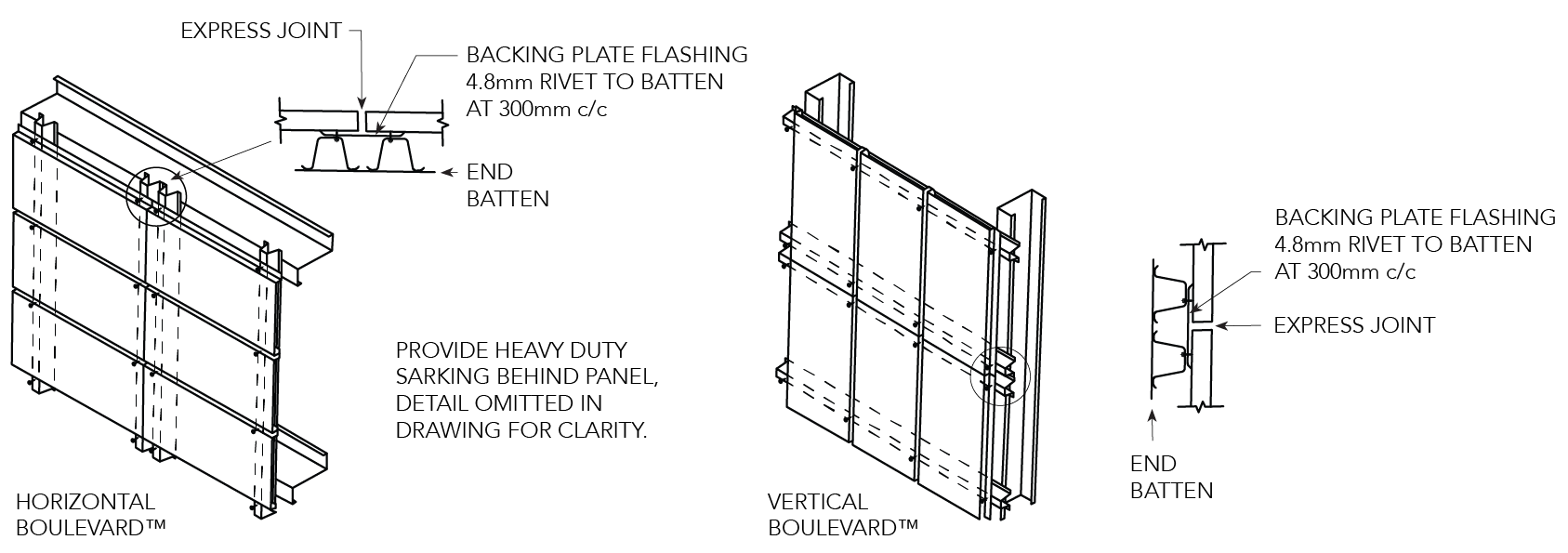
Figure BL ID CY 006
Top of Facade/ Parapet — Horizontal Panels
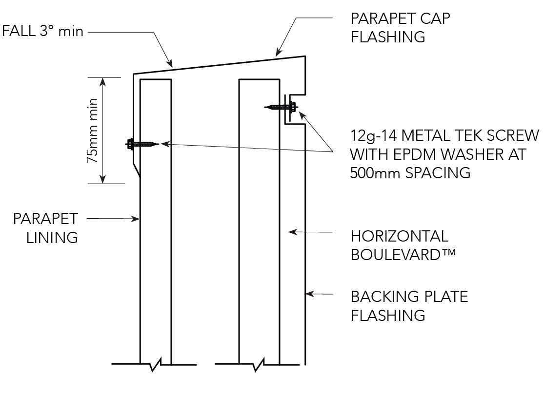
Figure BL ID CY 007
Top of Facade/ Parapet — Vertical Panels
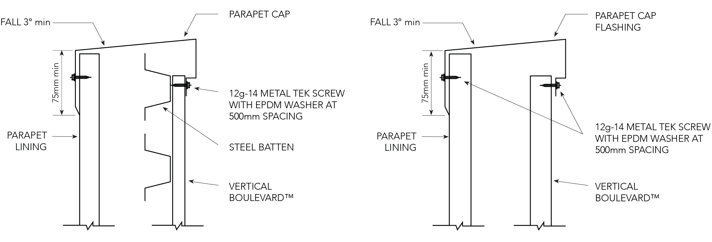
Figure BL ID CY 008
Pitched Roof
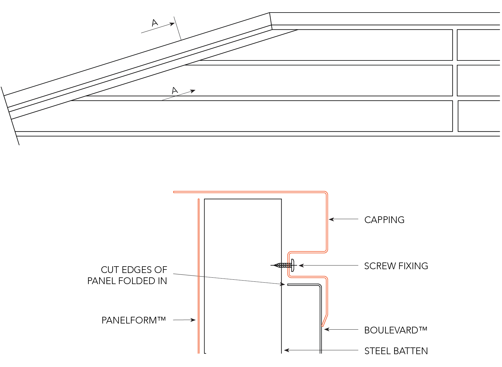
Figure BL ID CY 009
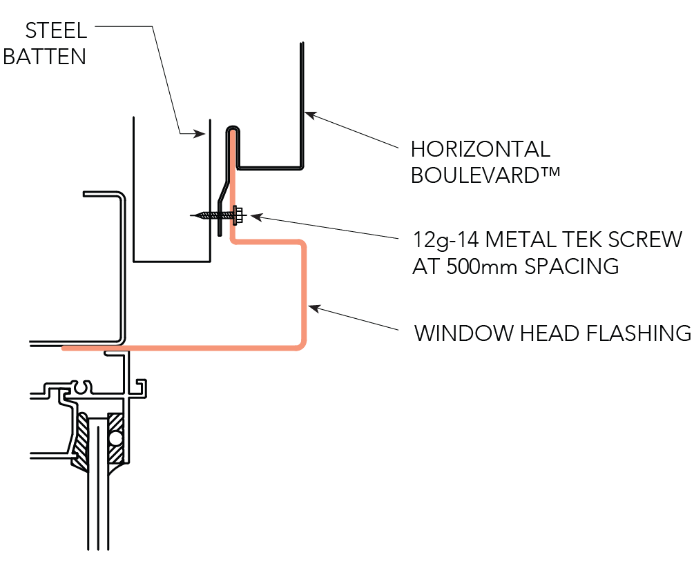
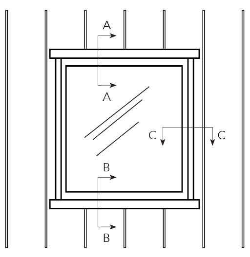
Window Details - Horizontal Panels
Horizontal Panel around opening
Figure BL ID CY 010
Section D-D Head
OPTION A
OPTION B
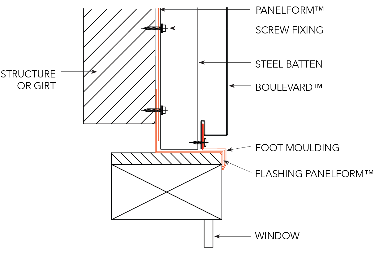
Figure BL ID CY 011
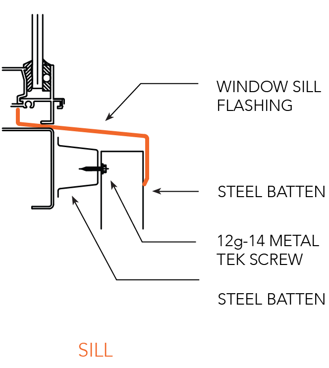
Section E-E Sill
OPTION A
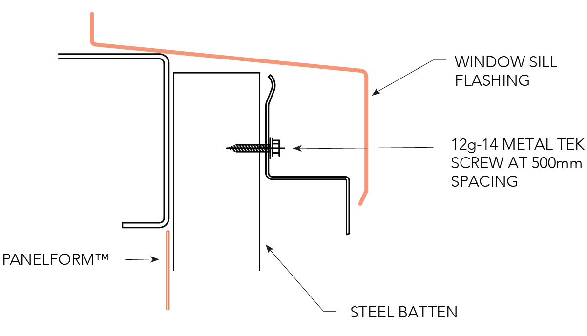
OPTION B
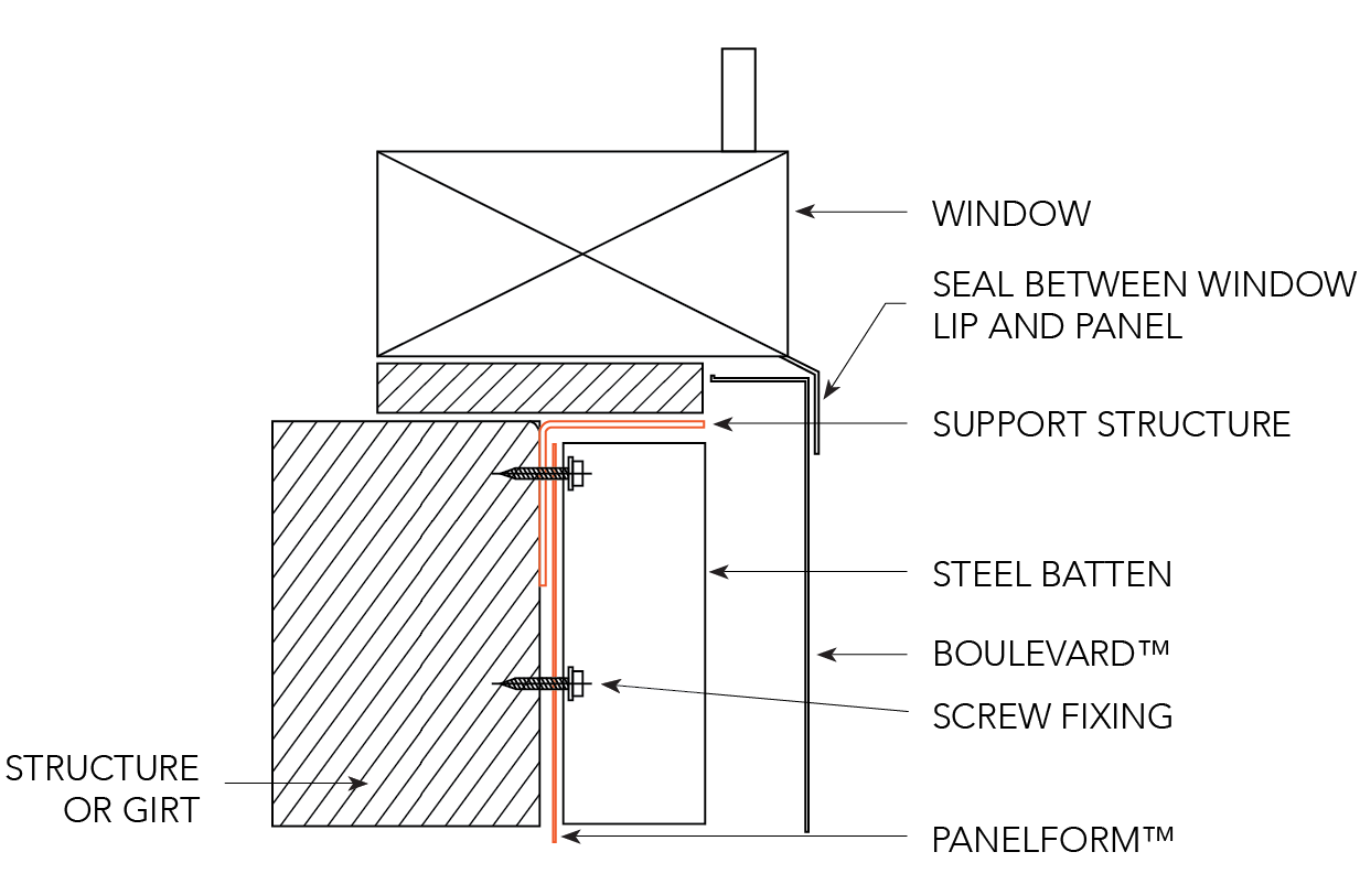
Figure BL ID CY 012
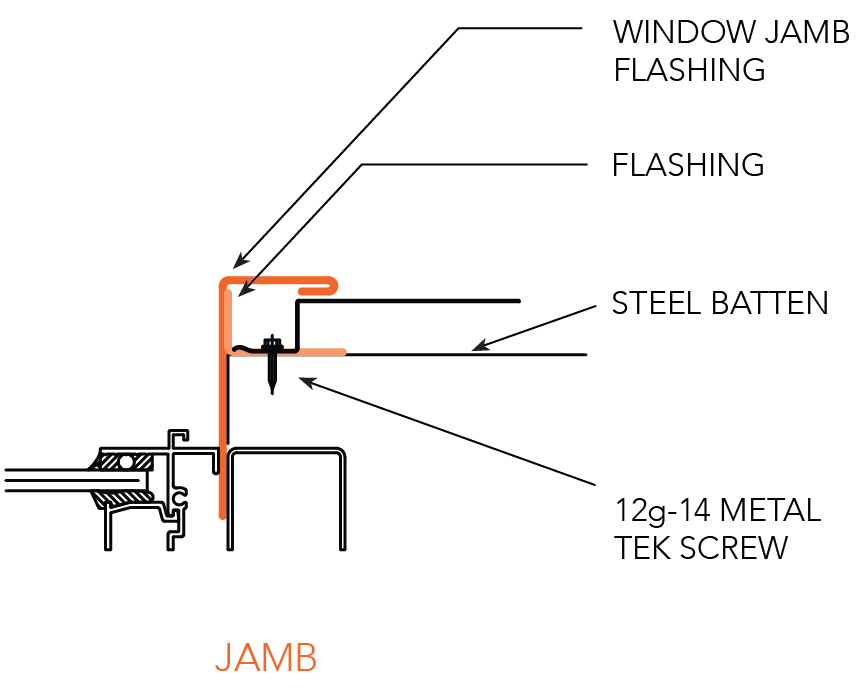
Section F-F Jamb
OPTION A
OPTION B

Figure BL ID CY 013
Window Details - Vertical Panels
VERTICAL PANEL AROUND OPENING
Vertical Panel around opening
SECTION A-A JAMB
SECTION B-B SILL
SECTION C-C HEAD
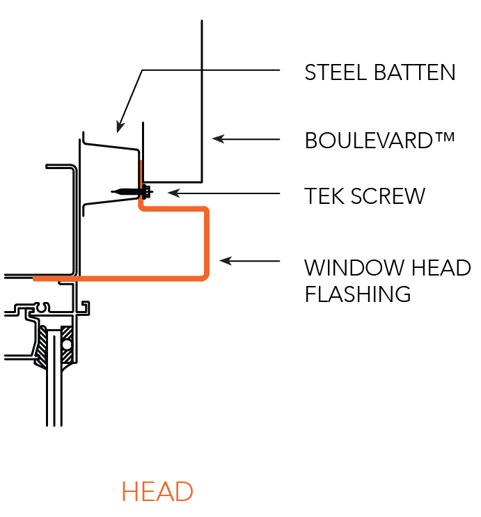
Figure BL ID CY 014
Express Joints
VERTICAL PANEL HORIZONTAL EXPRESS JOINT SECTION
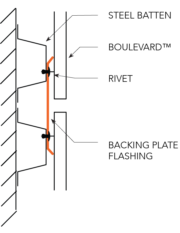
HORIZONTAL PANEL VERTICAL EXPRESS JOINT SECTION VIEW
OPTION A
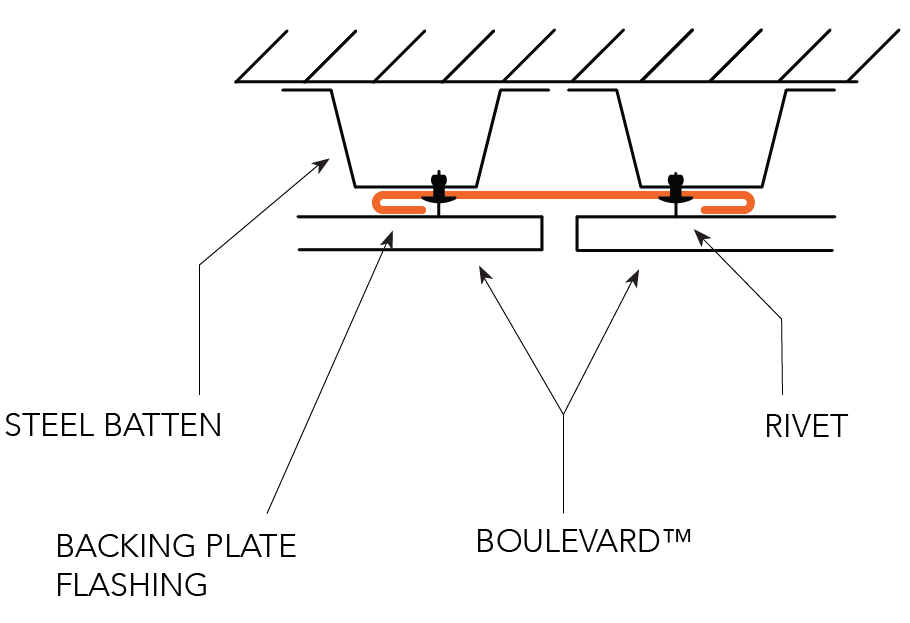
OPTION B
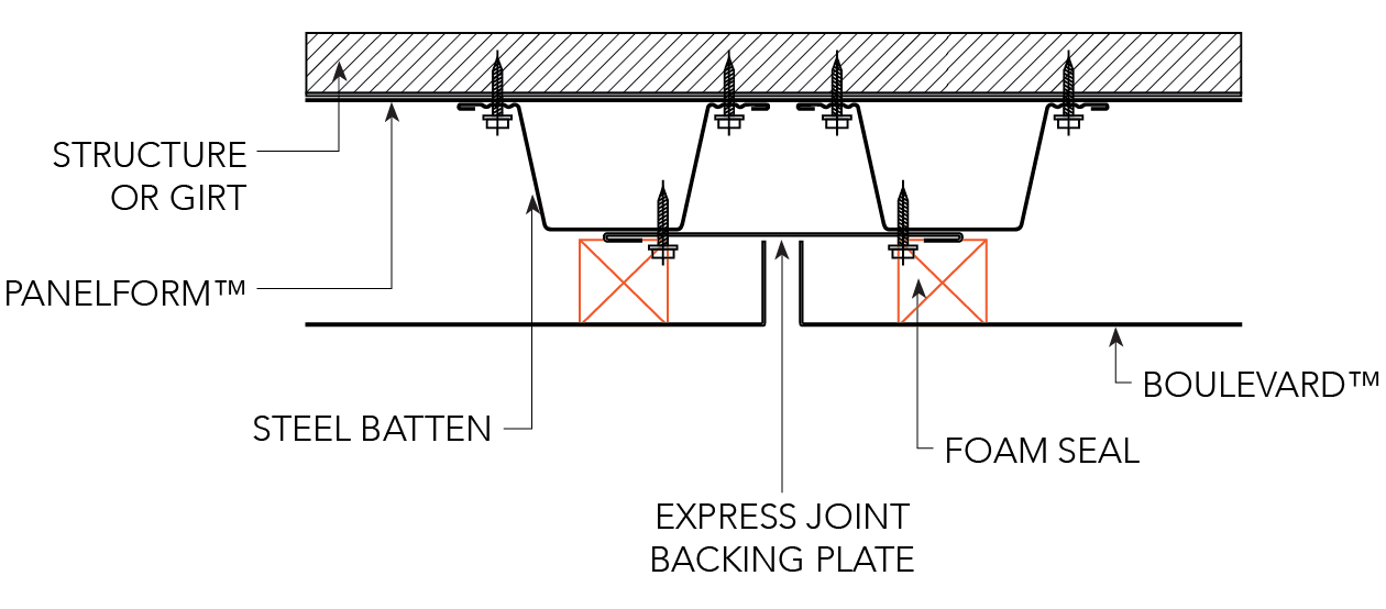
Figure BL ID CY 015
Express Joint Vertical Panel
OPTION A
OPTION B
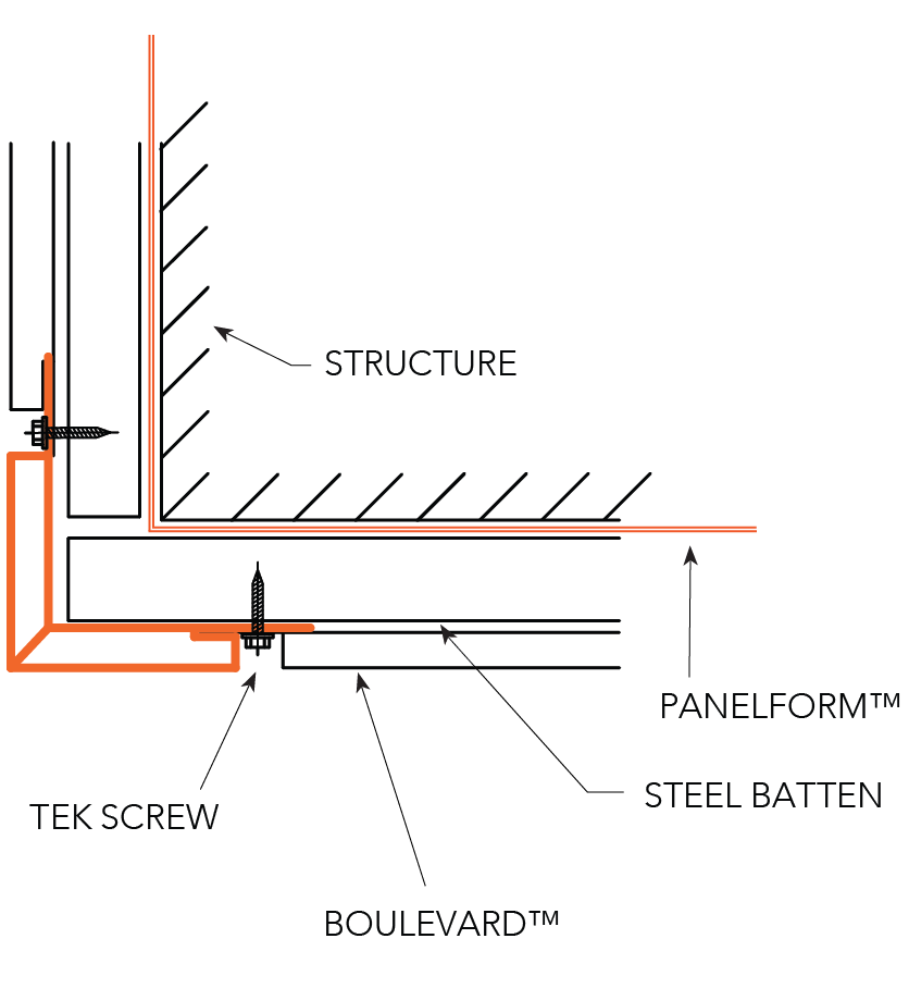
Figure BL ID CY 016
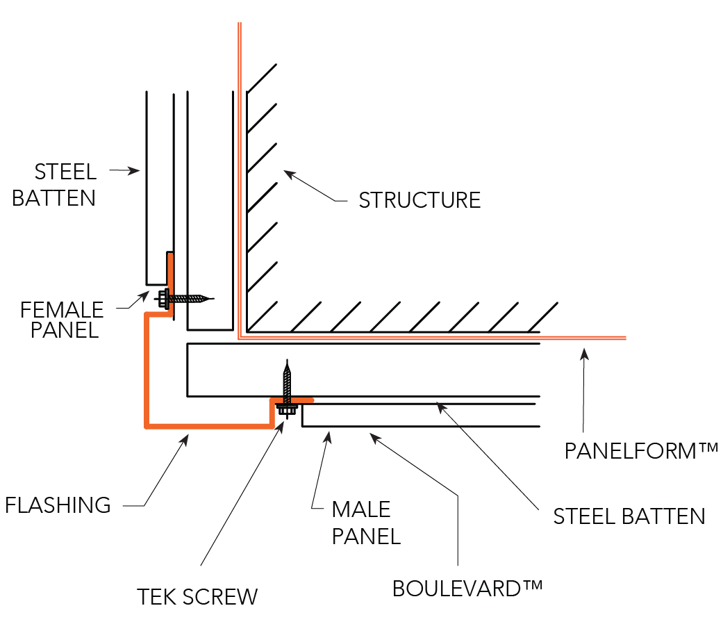
Internal Corner - Horizontal Panels
OPTION A
OPTION B

Figure BL ID CY 017
Interior Corner - Vertical Panels
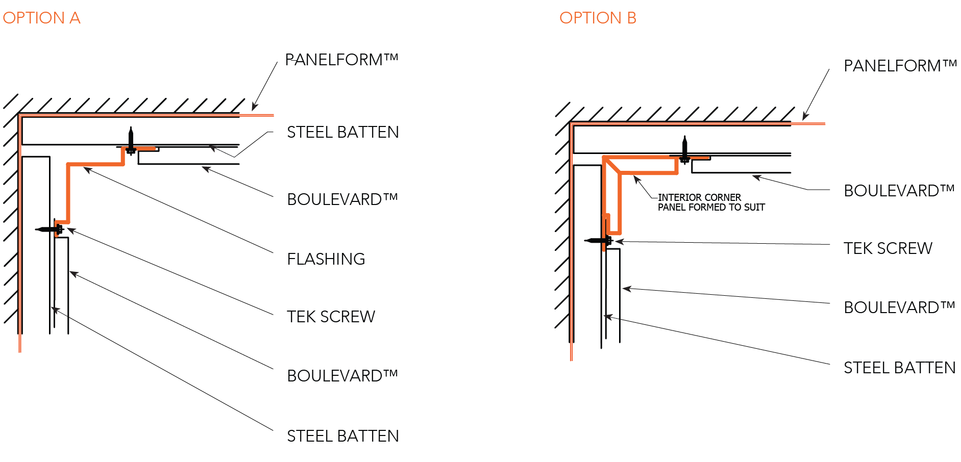
Figure BL ID CY 018
Exterior Corner - Horizontal Panels
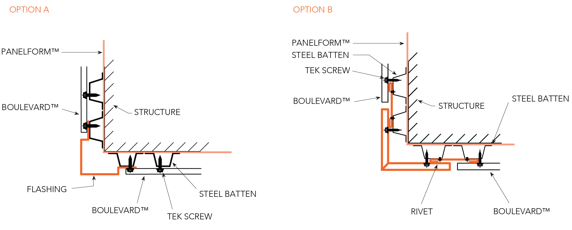
Figure BL ID CY 019
External Corner
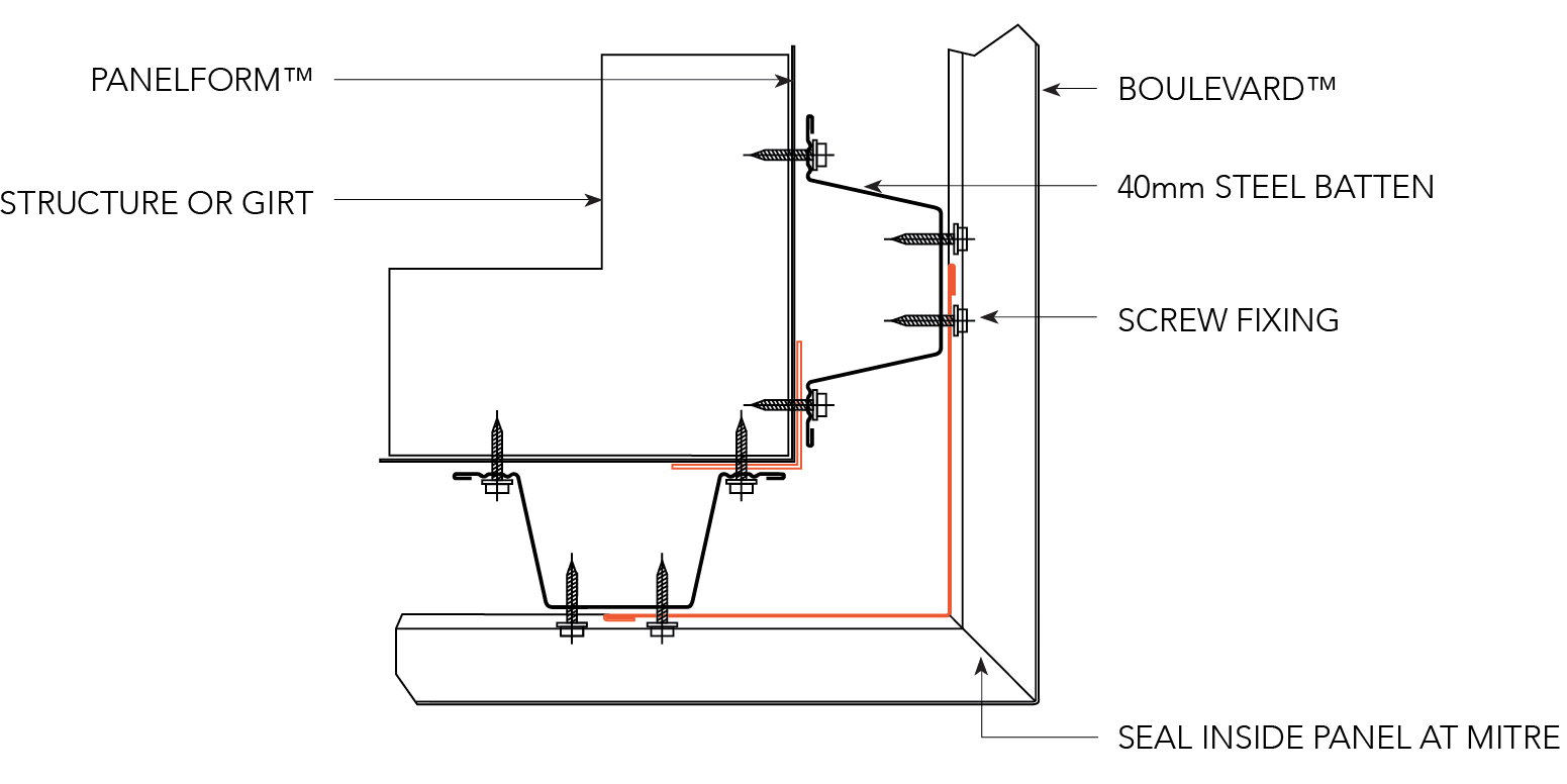
Figure BL ID CY 020
Exterior Corner - Vertical Panels
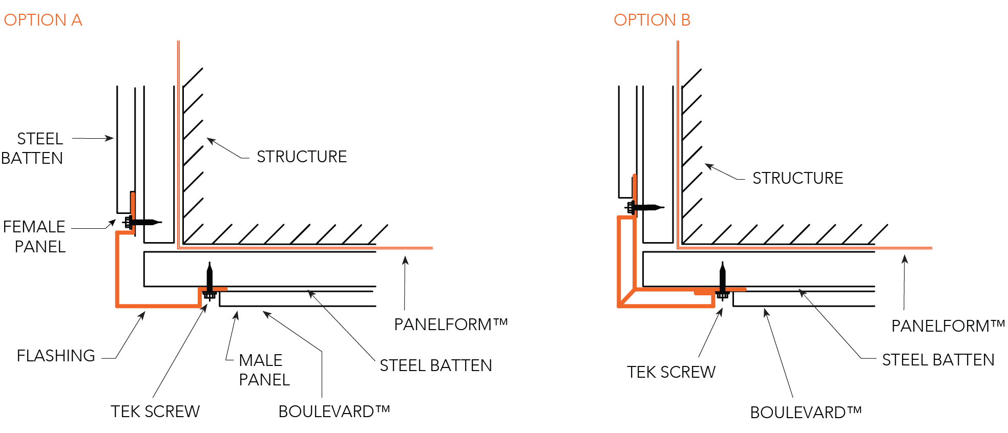
Figure BL ID CY 021
Foot Mould - Horizontal Panels
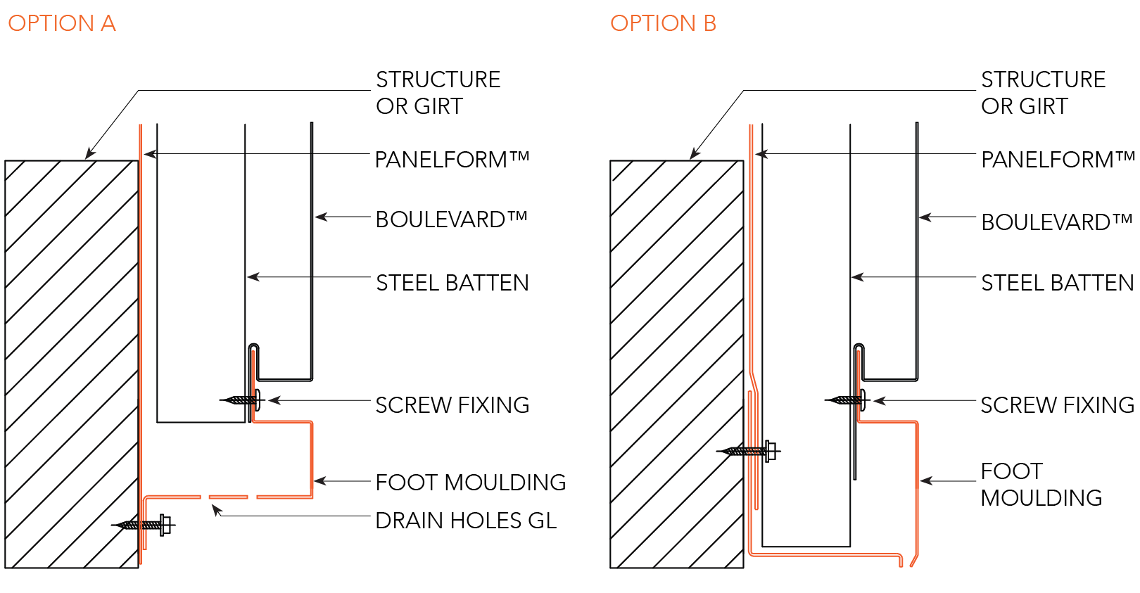
Figure BL ID CY 022
Foot Mould - Vertical Panels
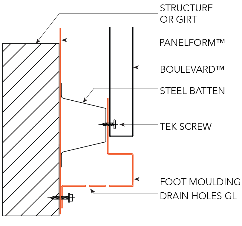
Figure BL ID CY 023
Side of Facade
Figure BL ID CY 024
Edge Detail
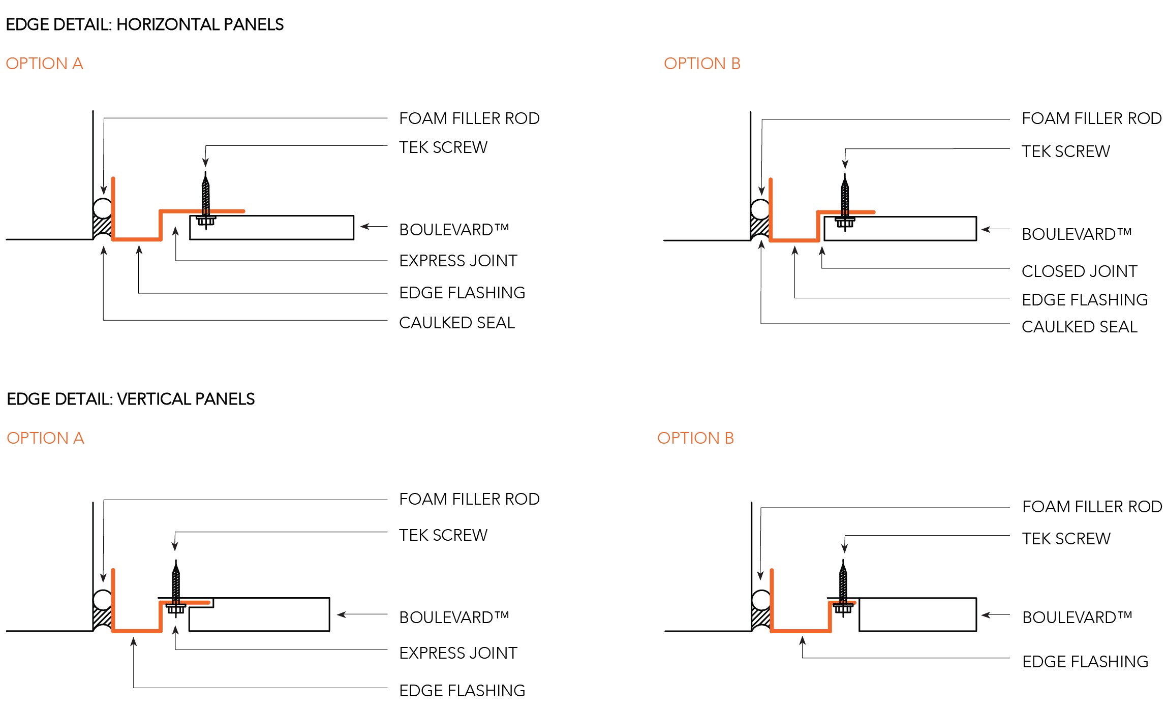
Figure BL ID CY 025
Typical Panel Section
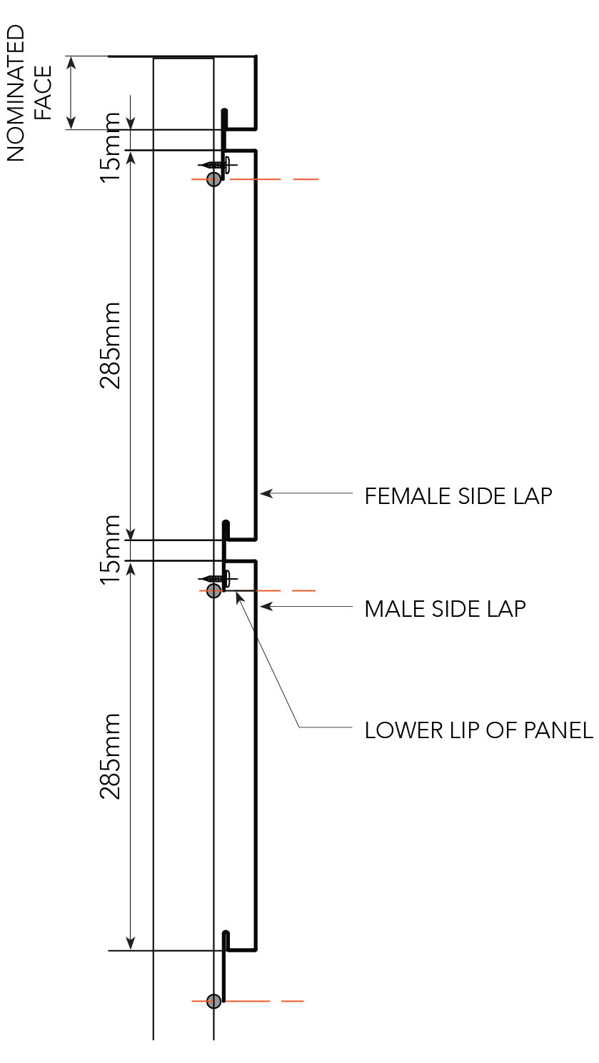
Figure BL ID CY 026
Panel Marking Matrix
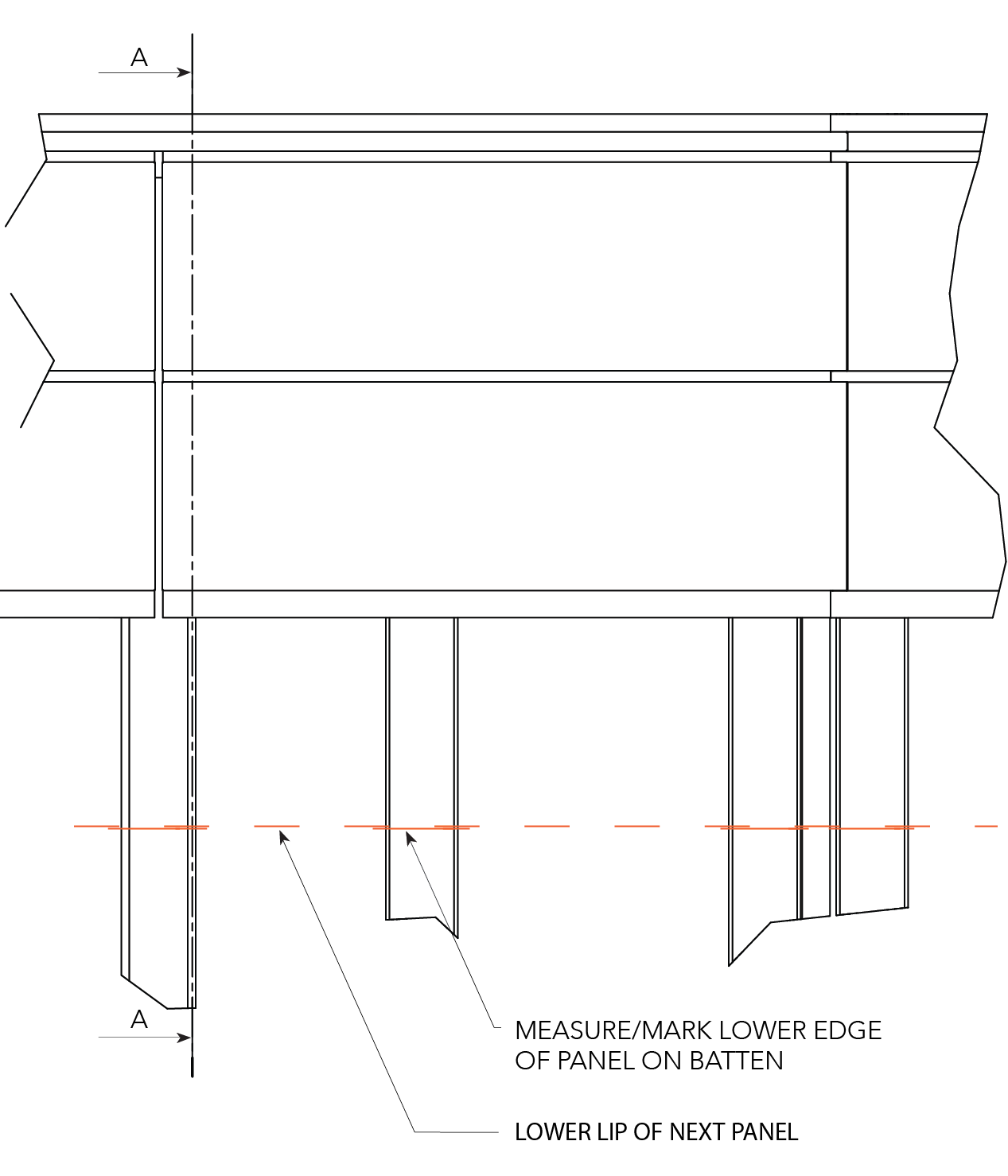
Figure BL ID CY 027
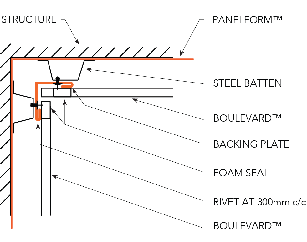
Backing Plates
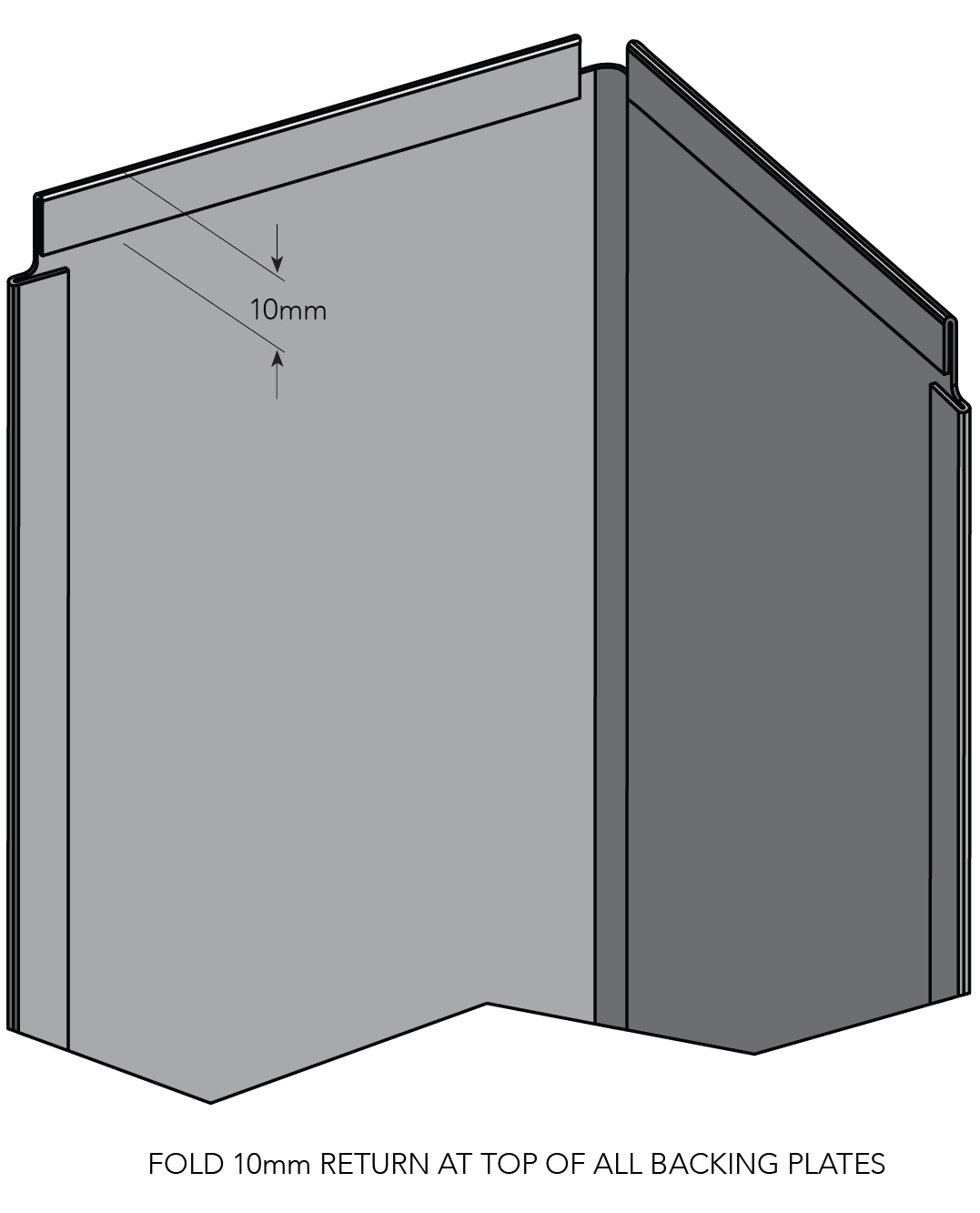
Figure BL ID CY 028
Foam Seal
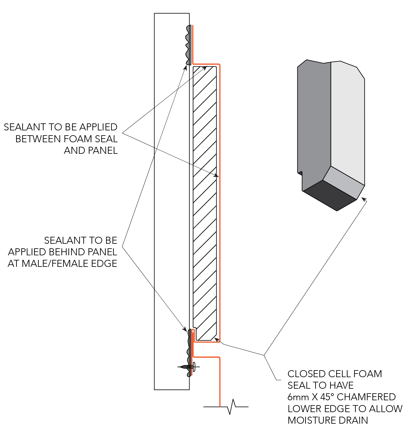
Figure BL ID CY 029
Note:
1. Foam is required for horizontal panels to stop water egress behind the panels.
2. Foam to be 30x30mm Biycell foam strip.