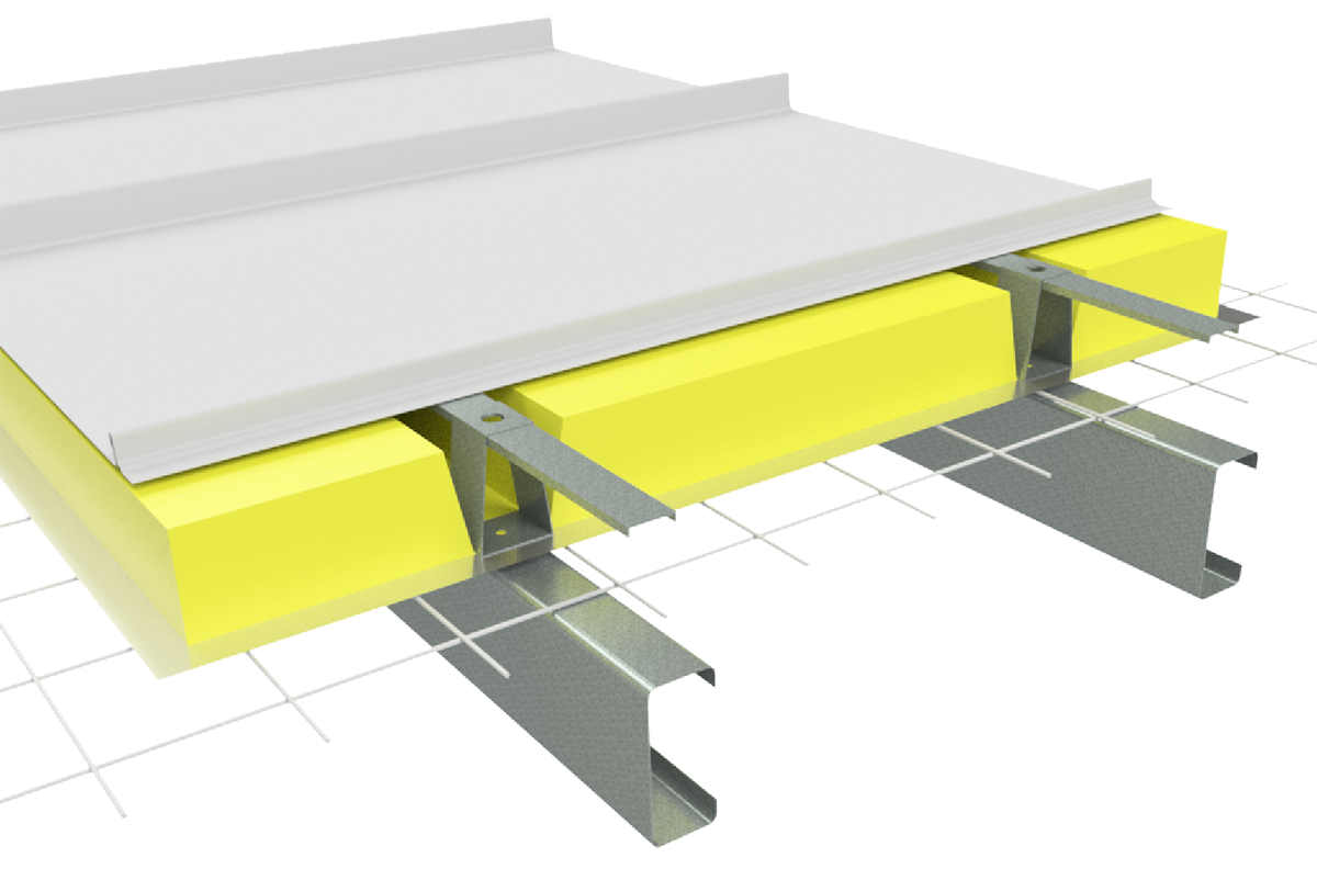
About Shadowline® 305 WA
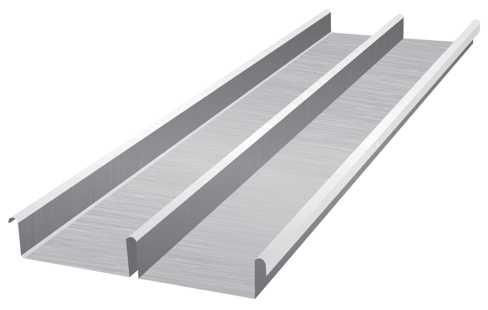
Fielders® Shadowline® 305 WA is a two pan, low-pitched roof deck that can be used down to a minimum of one degree pitch as a concealed fix button punched deck (see Figure SLWA IG NC 001) or as a pierced fix wall cladding. Fielders® Shadowline® 305 WA is only available in Western Australia.
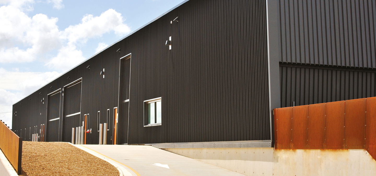
When used as a wall cladding Fielders® Shadowline® 305 WA can be fixed both horizontally and vertically through each pan to each girt with a hexagon head self-drilling and tapping screw. The exact specification is subject to project requirements. An unobtrusive fixing option is the ‘Irius’ screw from Power Fasteners.
Fielders® Shadowline® 305 WA can be rolled to any transportable length in ZINCALUME® with the full range of COLORBOND® colours in 0.70 BMT gauge.
Lead time for the Shadowline® 305 WA profile is subject to the material finish and the colour availability. Smaller quantities are available as a stock item, subject to normal rolling schedules. For substantial quantities the lead time generally does not exceed two to three weeks. Contact your local Fielders® office for further information.

Material Specifications
| Property | Notes | ||
| Base Metal Thickness (mm) | 0.70 | BMT | |
| Total Coated Thickness (mm) | 0.75* | TCT | |
| Mass / Unit Length | ZINCALUME® | 2.82 | kg/m |
| COLORBOND® | 2.85* | ||
| Mass / Unit Area | ZINCALUME® | 9.23 | kg/m2 |
| COLORBOND® | 9.36* | ||
| Minimum Yield Strength | G300 | Base Steel Designation | |
| Coating Class | AM100 - COLORBOND® Steel AM125 - ZINCALUME® AM150 - COLORBOND® Ultra Steel | Minimum Coating g/m2 of Zinc - Aluminium |
|
| Coverage (mm) | 305 | ||
| Tolerance | Sheet Length ±10mm Cover Width ±5mm | ||
| Thermal Expansion | 2.9mm average per 5m at 50°C change | ||
Notes:
- Shadowline® 305 WA is manufactured from materials in accordance to AS 1397 and AS 2728. It is to be installed in accordance with AS 1562 and HB 39.
- The sectional properties are theoretical values per sheet width. These properties are gross values only.
- *is based on Standard COLORBOND®; single-sided material. For other painted steel options please contact a Fielders® representative.
Rainfall Capacity
For further information, please refer to sections “Rainfall Intensity” and “Water Carrying Capacity and Rainwater Run-Off”.
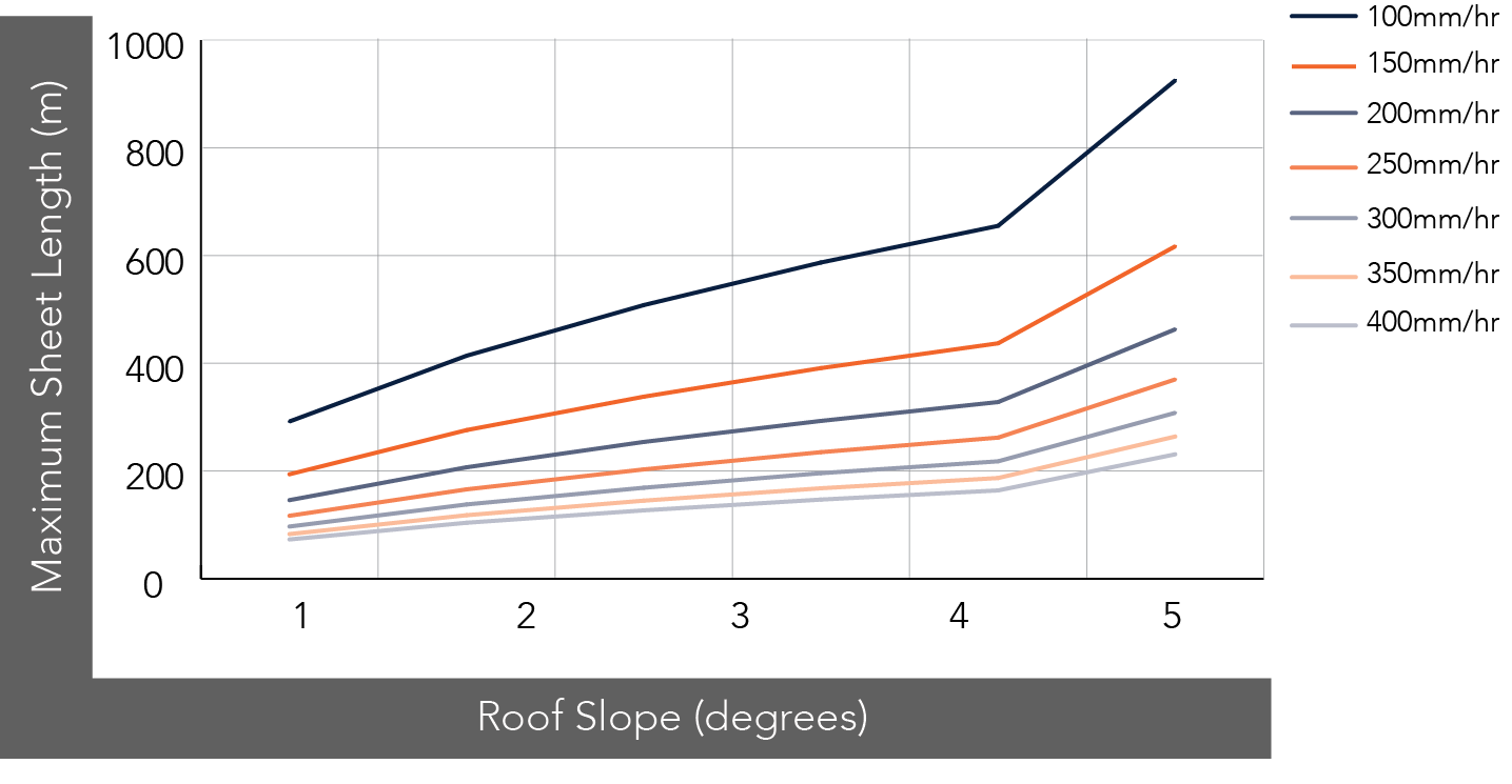
Figure SLWA RC NC 001
Maximum Roof Length (m)
| Roof Slope (degrees) | Rainfall Capacity (mm/hr) | ||||||
| 100 | 150 | 200 | 250 | 300 | 350 | 400 | |
| 1 | 292 | 194 | 146 | 117 | 97 | 83 | 73 |
| 2 | 414 | 276 | 207 | 166 | 138 | 118 | 104 |
| 3 | 508 | 338 | 254 | 203 | 169 | 145 | 127 |
| 4 | 587 | 391 | 293 | 235 | 196 | 168 | 147 |
| 5 | 655 | 437 | 328 | 262 | 218 | 187 | 164 |
| 10 | 925 | 617 | 463 | 370 | 308 | 264 | 231 |
Note:
- Minimum recommended slope is 1°. Sheet lengths greater than 24m are not recommended due to thermal expansion and contraction.
Shadowline® 305 WA Button Punched
Button punching is a concealed-fix roofing and walling installation option.
Refer to installation guidelines for further information.

Figure SLWA BP 001
Wind Load Capacity: Limit State Design: Button Punched: 0.70mm BMT
| Span (mm) | Single Span | End Span | Internal Span | |||
| Serv. (kPa) | Strength (kPa) | Serv. (kPa) | Strength (kPa) | Serv. (kPa) | Strength (kPa) | |
| 900 | 2.60 | 3.60 | 1.45 | 4.20 | 2.05 | 5.20 |
| 1200 | 2.10 | 3.25 | 1.45 | 3.80 | 1.90 | 4.90 |
| 1500 | 1.70 | 2.85 | 1.40 | 3.45 | 1.80 | 4.55 |
| 1800 | 1.35 | 2.70 | 1.35 | 3.15 | 1.65 | 4.15 |
| 2100 | 1.10 | 2.40 | 1.30 | 2.75 | 1.55 | 3.65 |
| 2400 | 0.95 | 2.20 | 1.25 | 2.45 | 1.45 | 3.05 |
| 2700 | 0.80 | 1.95 | 1.15 | 2.25 | 1.30 | 2.50 |
Note:
- Values in the table above have been generated based on testing into steel supports with at thickness of 1.0 mm.
- Values are based on no insulation under the sheeting.
- Serv. denotes serviceability
Figure SLWA NC 001 End Spans, Internal Spans and Overhangs illustrates the terminology end spans, internal spans, and overhangs and their reference to the supporting substructure. This terminology has been used in the following Maximum Recommended Span and Wind Load Capacity tables.
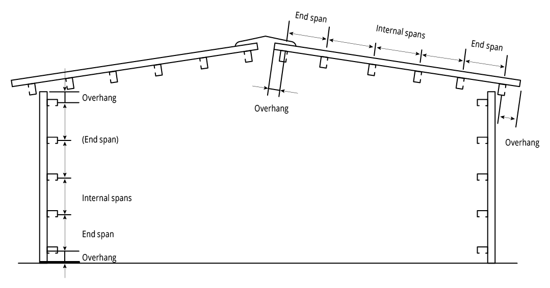
Figure SLWA NC 001 End Spans, Internal Spans and Overhangs
Maximum Recommended Roof Cladding Span
| Wind Region | Base Metal Thickness (mm) | Terrain Category 2 | Terrain Category 3 | ||||
| Single (mm) | End (mm) | Internal (mm) | Single (mm) | End (mm) | Internal (mm) | ||
| A | 0.70 | 1500 | - | 2500 | 1800 | 2000 | 2500 |
| B | 0.70 | - | - | 2500 | 1800 | 2000 | 2500 |
Importance Level 2
Maximum Roof Height H = 10m
External Pressure Coefficients:
Cp,e = -0.65 (walling)
Cp,e = -0.9 (roofing)
Internal Pressure Coefficient:
Cp,i = 0.2
Local Pressure Factors:
Kl = 2.0 (end & single spans)
Kl = 1.0 (internal spans)
Table SLWA RS NC 004 - Shadowline® WA Non-Cyclonic
Notes:
- Maximum roofing spans comply with both strength and serviceability wind pressure requirements.
- Spans shown in italics are limited by foot traffic requirements.
Maximum Recommended Wall Cladding Span
| Wind Region | Base Metal Thickness (mm) | Terrain Category 2 | Terrain Category 3 | ||||
| Single (mm) | End (mm) | Internal (mm) | Single (mm) | End (mm) | Internal (mm) | ||
| A | 0.70 | 1900 | 2200 | 2700 | 2500 | 2700 | 2700 |
| B | 0.70 | 1500 | 1400 | 2700 | 2300 | 2700 | 2700 |
Importance Level 2
Maximum Roof Height H = 10m
External Pressure Coefficients:
Cp,e = -0.65 (walling)
Cp,e = -0.9 (roofing)
Internal Pressure Coefficient:
Cp,i = 0.2
Local Pressure Factors:
Kl = 2.0 (end & single spans)
Kl = 1.0 (internal spans)
Table SLWA RS NC 003 - Shadowline® WA Non-Cyclonic
Notes:
- Maximum walling spans comply with both strength and serviceability wind pressure requirements.
Shadowline® 305 WA Pierced Fixed
A pierced fixed wall cladding installation option is also available.
Refer to installation guidelines for further information.

Figure SLWA PF 001
Wind Load Capacity: Limit State Design: Pierced Fixed: 0.70mm BMT
| Span (mm) | End Span | Internal Span | ||
| Serv. (kPa) | Strength (kPa) | Serv. (kPa) | Strength (kPa) | |
| 900 | 4.09 | 12.09 | - | - |
| 1200 | 3.63 | 9.34 | 4.24 | 12.09 |
| 1500 | 3.48 | 7.16 | 3.50 | 9.34 |
| 1800 | 3.21 | 5.09 | 3.27 | 7.16 |
| 2100 | 2.74 | 3.67 | 3.09 | 5.09 |
| 2400 | 2.46 | 3.63 | 2.74 | 3.67 |
| 2700 | 1.98 | 3.09 | - | - |
| 3000 | 1.78 | 2.88 | - | - |
| 3300 | 1.49 | 2.38 | - | - |
Note:
- Serv. denotes serviceability
Button punching is a concealed-fix roofing and walling installation option.
Refer to installation guidelines for further information.
Figure SLWA BP 001
Maximum Recommended Roof Cladding Span
| Wind Region | Base Metal Thickness (mm) | Terrain Category 2 | Terrain Category 3 | ||||
| Single (mm) | End (mm) | Internal (mm) | Single (mm) | End (mm) | Internal (mm) | ||
| A | 0.70 | 3000* | 3000* | 3000* | 3000* | 2000 | 2500 |
| B | 0.70 | 3000* | 3000* | 3000* | 3000* | 2000 | 2500 |
Importance Level 2
Maximum Roof Height H = 10m
External Pressure Coefficients:
Cp,e = -0.65 (walling)
Cp,e = -0.9 (roofing)
Internal Pressure Coefficient:
Cp,i = 0.2
Local Pressure Factors:
Kl = 2.0 (end & single spans)
Kl = 1.0 (internal spans)
Table SLWA RS NC 002 - Shadowline® WA Non-Cyclonic
Notes:
- Maximum roofing spans comply with both strength and serviceability wind pressure requirements.
- Spans shown in italics are limited by foot traffic requirements.
- * Spans in excess of 3000mm may be available subject to enquiry. Long spans require particular attention to installation practice.
Maximum Recommended Wall Cladding Span
| Wind Region | Base Metal Thickness (mm) | Terrain Category 2 | Terrain Category 3 | ||
| End (mm) | Internal (mm) | End (mm) | Internal (mm) | ||
| A | 0.70 | 3000* | 3000* | 3000* | 3000* |
| B | 0.70 | 3000* | 3000* | 3000* | 3000* |
Importance Level 2
Maximum Roof Height H = 10m
External Pressure Coefficients:
Cp,e = -0.65 (walling)
Cp,e = -0.9 (roofing)
Internal Pressure Coefficient:
Cp,i = 0.2
Local Pressure Factors:
Kl = 2.0 (end & single spans)
Kl = 1.0 (internal spans)
Table SLWA RS NC 001 - Shadowline® WA Non-Cyclonic
Notes:
- Maximum walling spans comply with both strength and serviceability wind pressure requirements.
- *Spans in excess of 3000mm may be available subject to enquiry. Wall applications or long spans require particular attention to installation practice.
Installation
Installation Guide: Button Punched (Concealed Fixed)
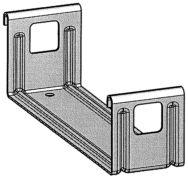
Figure SLWA NC 001
Step 1
Fix a clip to the first and last purlin.
Step 2
Attached a string line to the first and last clip as a guide to fix the remainder of the clips to the purlins in between.
Step 3
Place the first sheet over the clips with the correct length into the gutter.
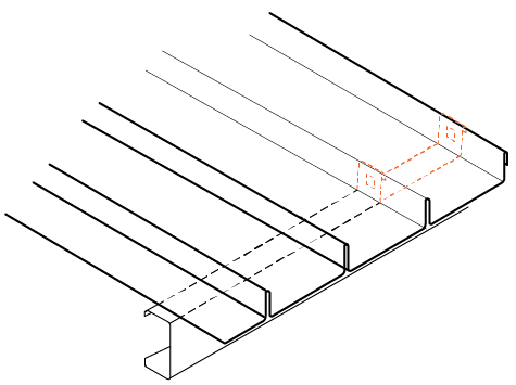
Figure SLWA IG NC 001
Step 4
Using the rib closing tool squeeze the male rib of the first sheet. Place top clip over each squashed male rib and fix to purlin. This needs to be done to prevent the sheet from lifting in the wind before the barges are fitted. The use of string lines will assist in ensuring sheets are installed straight.
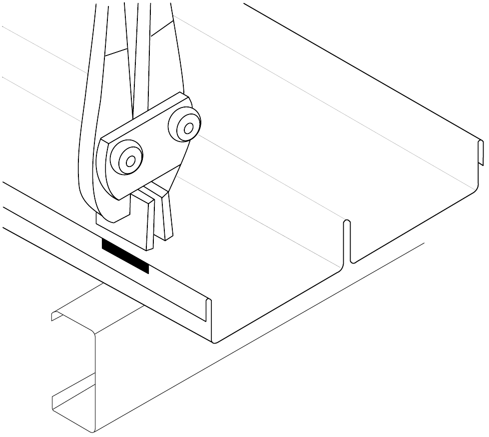
Figure SLWA IG NC 002
Step 5
Make a small non-permanent mark in the pan to enable you to locate the clips in the latter locking operation with the button punch.
Step 6
Position the female rib of the next sheet over the male rib and clips ensuring that it is fully engaged. Fully engage the sheet with the clips using foot pressure on the ribs over each clip. You can do this by walking along the full length of the sheet with one foot in the tray next to the overlapping rib and the other foot applying pressure to the top of the interlocking ribs at regular intervals.
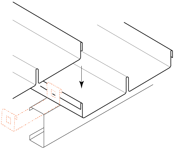
Figure SLWA IG NC 003
Step 7
Repeat steps 3 to 5.
Step 8
All lapped ribs must be locked along their length, by button punching at the clips, and if necessary between the clips (typically at 900mm centre to centre). Punching to a string line guide stretched across the sheeting is recommended as random punching marks the appearance of the finished work.
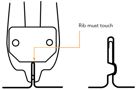
Figure SLWA IG NC 004
You must button punch through the hole in each top fixing clip, you can locate the clip with the non-permanent mark made previously. When operating the punching tool, stand on the pan of the overlapping sheet to ensure that the sheets are fully engaged.
Ends of Sheets
Wind can drive water uphill under the flashings or cappings. Also, at the low end of a roof, wind or capillary action can cause water to run back up the underside of the sheeting. To minimise these problems, turn the pans up at the top of sheets, and turn them down at the bottom. A tool is available for these jobs (ref. Figure SLWA IG NC 005).
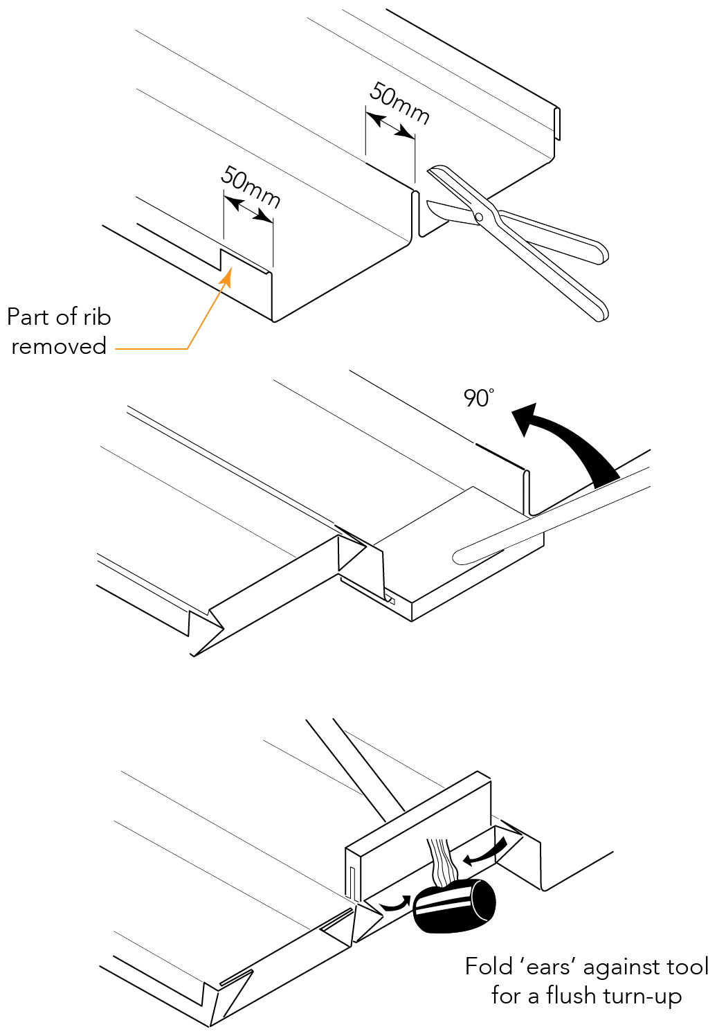
Figure SLWA IG NC 005
Turning-up
Flush turn-ups are usually used on Shadowline® 305 WA. Cut off a portion of the female rib for at least 50mm. For a flush turn-up, you also need to cut the crown of the centre rib for at least 50mm.
Holding the end of the tool against the end of the sheet, pull the handle up 90°. If turning-up flush, fold the protruding ears flush against the turn-up tool with a rubber mallet (ref. Figure SLWA IG NC 005).
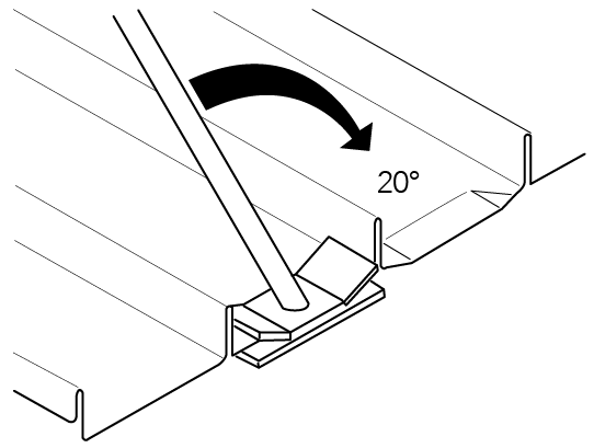
Figure SLWA IG NC 006
Turning-down
All roofing on slopes below 1 in 5 (10°) must be turned-down.
Turning-down is usually done after the sheeting is fixed on the roof, provided there is no obstruction to the operation of the turn-down tool.
Push the turn-down tool over the end of the tray, as far as it will go.
Hold the tool hard against the end of the tray and push the handle to form a turn-down of about 20° (ref. Figure SLWA IG NC 006).
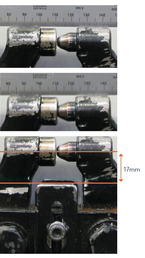
Setting Your Button Punch
Step 1
First set the depth that the button punch will punch.
Step 2
Place the button punch on its handles and lean it against a support with the button lining up with the face of the cup.
Step 3
Measure between the two punch holders (in photo about 24mm).
Step 4
Close the handles until the gap decreases by 2.0mm.
Step 5
Adjust the stop adjustment until it is set at that distance.
Step 6
Setting the distance down from the top of the rib of the roof sheet that the button punch is located.
Step 7
The distance from the centre of the button punch to the support guides is 17mm as shown.
Step 8
If this needs to be adjusted, loosen the set screws, adjust the stop and retightened.
Step 9
After you do the first button punch check that it is in fact punching to that dimension.
Step 10
Some minor adjustment may be required as it should punch in the centre of the hole in the clip.
Recommended Fasteners
Recommended Fasteners Button Punched
| Supports | Recommended Fastener (Without Insulation) |
| Steel 1.0 to 3.5mm | 10g-16x16mm Wafer Head Tek Screw |
| Timber Hardwood | 10g-12x25mm Wafer Head Type 17 Screw |
| Timber Softwood | 10g-12x25mm Wafer Head Type 17 Screw |
| Steel Battens (0.55 to 1.0mm) | 10g-16x16mm Wafer Head Tek Screw |
Recommended Fasteners Pierced Fixed
| Supports | Recommended Fastener (Without Insulation) |
| Steel 1.0 to 3.5mm | 14g-10x25mm Hex Head Tek Screw |
| Timber Hardwood | 14g-10x25mm Hex Head Type 17 Screw |
| Timber Softwood | 14g-10x25mm Hex Head Type 17 Screw |
| Steel Battens (0.55 to 1.0mm) | 14g-10x25mm Hex Head Tek Screw |
Roof to Wall Connection Detail 1
Step 1 - Rib Caps Cut and Folded from Flat Sheet
Development of Cap on Flat Sheet
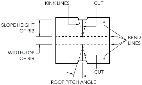
Figure SLWA IG NC 007
Step 2
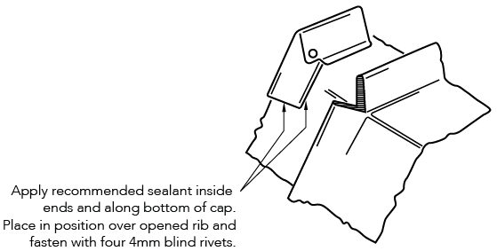
Figure SLWA IG NC 008
Step 3
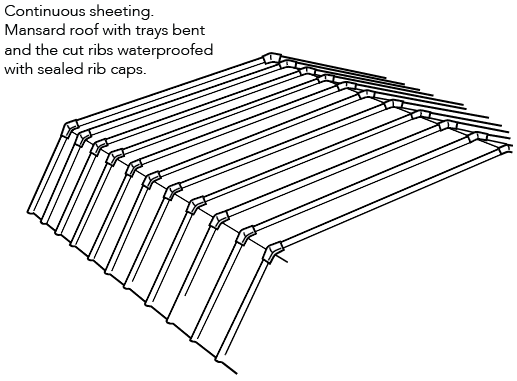
Figure SLWA IG NC 009
Roof to Wall Connection Detail 2
Step 1
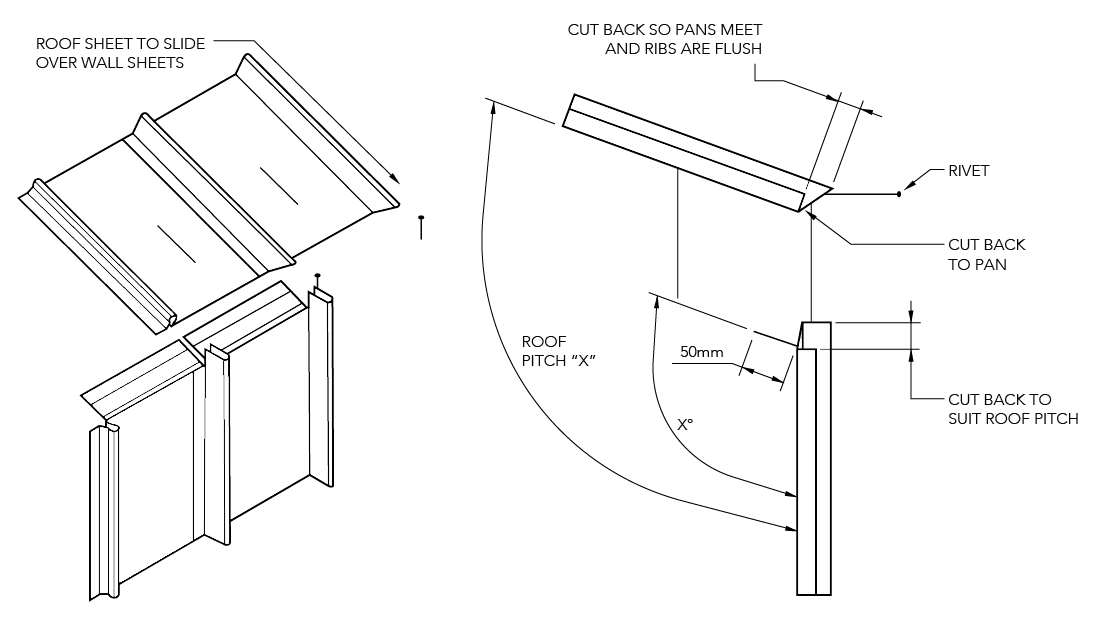
Figure SLWA IG NC 010
Step 2
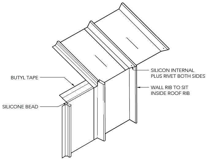
Figure SLWA IG NC 011
Step 3
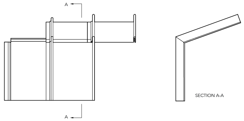
Figure SL IG NC 012
Maximum Sheet Length
See section “Thermal Expansion and Contraction of Steel Sheeting”.
Designing Without Step Joints
Refer to section "Long Length Roofing Solutions".
Insulation
Care needs to be taken when installing insulation with Shadowline® 305 WA roof sheeting. When insulation thicknesses up to 50mm are installed the screws may need to be increased depending on the thickness and density of the insulation. When the screw is properly tightened into metal there should be a minimum of three (3) threads protruding past the support being fixed in to. For timber, the screw must have a minimum embedment of 25mm into timber.
When insulation is required in conjunction with Finesse® profiles, Fielders® recommend the use of a thermal spacer to help maintain Rw values as well as minimising any bulging in the profile caused by the insulation.
Insulation blankets and batts can cause wide flat pan cladding to bow out between the supports, between fasteners along the support, or bow the pans. For insulation blankets and batts as well as more dense glass wool and rock wool, and thicker insulation, spacers are recommended.