About Spanform™
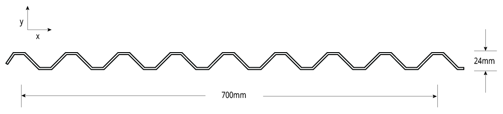
Spanform™ is the multi-rib and multi-purpose roofing and walling panel from Fielders®. Offering impressive spanning qualities and optimum durability, Spanform™ provides the flexibility you need to design and build a variety of steel projects. Using innovative design, Spanform™ has higher and squarer ribs to provide its impressive strength. Despite being similar to corrugated steel in appearance, Spanform™ can achieve much more as a steel roofing and walling product. Available in long lasting ZINCALUME® and COLORBOND® steel, suitable as either roofing or walling product.

Material Specifications
| Property | Notes | |||
| Base Metal Thickness (mm) | 0.42 | 0.48 | BMT | |
| Total Coated Thickness (mm) | 0.47* | 0.53* | TCT | |
| Mass / Unit Length | ZINCALUME® | 3.30 | 3.70 | kg/m |
| COLORBOND® | 3.36* | 3.77* | ||
| Mass / Unit Area | ZINCALUME® | 4.71 | 5.29 | kg/m2 |
| COLORBOND® | 4.48* | 5.38* | ||
| 2nd moment of area about principal axis (103 mm4) | Ix | 35 | 40 | |
| Iy | 19840 | 22670 | ||
| Section modulus about principal axis (103 mm3) | Zx | 3 | 3 | |
| Zy | 52 | 59 | ||
| Warping Constant (109 mm6) | Iw | 2 | 2 | |
| Torsion Constant (mm4) | J | 24 | 35 | |
| Minimum Yield Strength | G550 | Base Steel Designation | ||
| Coating Class | Z600 (Heritage Galvanised) AM100 (COLORBOND® Steel) AM125 (ZINCALUME®) AM150 (COLORBOND® Ultra Steel) Z450 (Galvanised) | Minimum Coating g/m2 of Zinc - Aluminium |
||
| Coverage (mm) | 700 | |||
| Tolerance | Sheet Length ±7mm Cover Width ±4mm | |||
| Thermal Expansion | 2.9mm average per 5m at 50°C change | |||
Notes:
- SpanformTM is manufactured from materials in accordance to AS 1397 and AS 2728. It is to be installed in accordance with AS 1562 and HB 39.
- The sectional properties are theoretical values per sheet width. These properties are gross values only.
- *is based on Standard COLORBOND®; single-sided material. For other painted steel options please contact a Fielders® representative.
Rainfall Capacity
For further information, please refer to sections "Rainfall Intensity" and "Water Carrying Capacity and Rainwater Run-Off".
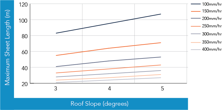
Figure SF RC CY 001
Maximum Roof Length (m)
| Roof Slope (degrees) | Rainfall Capacity (mm/hr) | ||||||
| 100 | 150 | 200 | 250 | 300 | 350 | 400 | |
| 3 | 83 | 55 | 41 | 33 | 28 | 24 | 21 |
| 4 | 95 | 64 | 48 | 38 | 32 | 27 | 24 |
| 5 | 107 | 71 | 53 | 43 | 36 | 31 | 27 |
Note:
- Minimum recommended slope is 3°. Sheet lengths greater than 24m are not recommended due to thermal expansion and contraction.
Load Span Tables
Cyclonic Testing
Fielders® have undertaken extensive and comprehensive testing on our roofing profiles for cyclonic regions. The following tables provide wind capacities and span values for the SpanformTM roofing profile in cyclonic region.
The cyclonic wind load capacities for SpanformTM roofing profile is shown in Table SF WC CY 001 below.
Figure SF CY 002 End Spans, Internal Spans and Overhangs illustrates the terminology end spans, internal spans, and overhangs and their reference to the supporting substructure. This terminology has been used in the following Maximum Recommended Span and Wind Load Capacity tables.
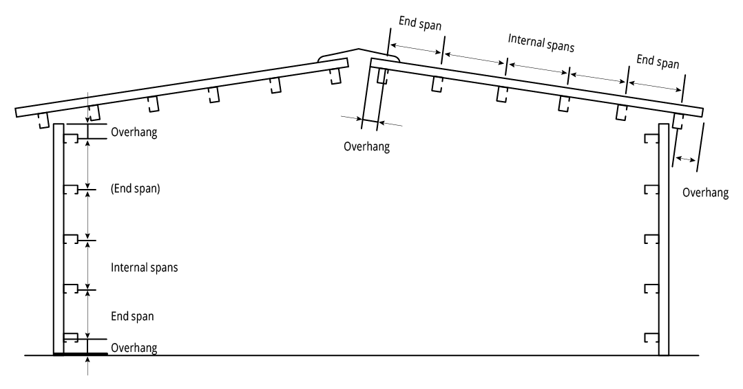
Figure SF CY 002 End Spans, Internal Spans and Overhangs
Wind Load Capacity: Strength Limit State Design: 0.42mm BMT
| Span (mm) | Single Span (kPa) | Double Span (kPa) | Multi (kPa) | |
| End Span | Internal Span | |||
| 900 | 12.45 | 7.59 | 6.14 | - |
| 1200 | 7.20 | 4.74 | 4.15 | 5.91 |
| 1500 | 4.70 | 3.30 | 3.07 | 4.31 |
| 1800 | 3.32 | 2.45 | 2.39 | 3.33 |
| 2100 | - | - | - | 2.68 |
Wind Load Capacity: Strength Limit State Design: 0.48mm BMT
| Span (mm) | Single Span (kPa) | Double Span (kPa) | Multi Spans (kPa) | |
| End Span | Internal Span | |||
| 900 | 14.31 | 8.60 | 7.60 | - |
| 1200 | 8.25 | 5.41 | 4.95 | 7.09 |
| 1500 | 5.39 | 3.78 | 3.55 | 5.02 |
| 1800 | 3.80 | 2.82 | 2.70 | 3.78 |
| 2100 | - | - | - | 2.98 |
Cyclonic Load Span Tables - Region C
Maximum Allowable Roof Spans for building heights ≤ 5m: Region C: 0.42mm BMT
| Terrain Category | Roof Area Notation & Uplift (kPa)* | Single Span (mm) | Double Span (mm) | Multi Spans (mm) | |
| End Span | Internal Span | ||||
| 1 & 2 | D - 4.18 | 1590 | 1300 | 1190 | 1530 |
| F - 5.35 | 1400 | 1110 | 990 | 1290 | |
| G - 6.53 | 1260 | 990 | 860 | 1120 | |
| 2.5 | D - 3.54 | 1740 | 1430 | 1350 | 1720 |
| F - 4.54 | 1530 | 1230 | 1120 | 1440 | |
| G - 5.54 | 1380 | 1090 | 970 | 1250 | |
Pa,r = 1:500
Vr = 66 m/s for Region C
Vr = 88 m/s for Region D
Md = 1.00
Fc = 1.05
FD = 1.1
Ms = 1.00
Mt = 1.00
Cp,i = 0.70
Cp,e = - 0.90
KL = 1.5 for Area F
KL = 2.0 for Area G
Table SF RS CY 001A - Spanform™ Cyclonic
Note:
- * Pressure is total ultimate value
Maximum Allowable Roof Spans for building heights ≤ 5m: Region C: 0.48mm BMT
| Terrain Category | Roof Area Notation & Uplift (kPa)* | Single Span (mm) | Double Span (mm) | Multi Spans (mm) | |
| End Span | Internal Span | ||||
| 1 & 2 | D - 4.18 | 1710 | 1410 | 1340 | 1690 |
| F - 5.35 | 1500 | 1210 | 1140 | 1440 | |
| G - 6.53 | 1350 | 1070 | 1000 | 1260 | |
| 2.5 | D - 3.54 | 1870 | 1560 | 1500 | 1880 |
| F - 4.54 | 1640 | 1340 | 1270 | 1600 | |
| G - 5.54 | 1480 | 1180 | 1110 | 1410 | |
Pa,r = 1:500
Vr = 66 m/s for Region C
Vr = 88 m/s for Region D
Md = 1.00
Fc = 1.05
FD = 1.1
Ms = 1.00
Mt = 1.00
Cp,i = 0.70
Cp,e = - 0.90
KL = 1.5 for Area F
KL = 2.0 for Area G
Table SF RS CY 001B - Spanform™ Cyclonic
Note:
- * Pressure is total ultimate value
Maximum Allowable Roof Spans for building heights 5m-10m: Region C: 0.42mm BMT
| Terrain Category | Roof Area Notation & Uplift (kPa)* | Single Span (mm) | Double Span (mm) | Multi Spans (mm) | |
| End Span | Internal Span | ||||
| 1 & 2 | D - 4.63 | 1510 | 1220 | 1110 | 1420 |
| F - 5.93 | 1330 | 1050 | 920 | 1200 | |
| G - 7.23 | 1200 | 930 | 800 | 1040 | |
| 2.5 | D - 4.13 | 1600 | 1300 | 1200 | 1540 |
| F - 5.30 | 1410 | 1120 | 1000 | 1290 | |
| G - 6.46 | 1270 | 990 | 870 | 1120 | |
Pa,r = 1:500
Vr = 66 m/s for Region C
Vr = 88 m/s for Region D
Md = 1.00
Fc = 1.05
FD = 1.1
Ms = 1.00
Mt = 1.00
Cp,i = 0.70
Cp,e = - 0.90
KL = 1.5 for Area F
KL = 2.0 for Area G
Table SF RS CY 002A - Spanform™ Cyclonic
Note:
- * Pressure is total ultimate value
Maximum Allowable Roof Spans for building heights 5m-10m: Region C: 0.48mm BMT
| Terrain Category | Roof Area Notation & Uplift (kPa)* | Single Span (mm) | Double Span (mm) | Multi Spans (mm) | |
| End Span | Internal Span | ||||
| 1 & 2 | D - 4.63 | 1620 | 1320 | 1250 | 1580 |
| F - 5.93 | 1430 | 1130 | 1060 | 1350 | |
| G - 7.23 | 1290 | 1000 | 930 | 1180 | |
| 2.5 | D - 4.13 | 1720 | 1420 | 1350 | 1700 |
| F - 5.30 | 1510 | 1210 | 1140 | 1450 | |
| G - 6.46 | 1360 | 1070 | 1000 | 1270 | |
Pa,r = 1:500
Vr = 66 m/s for Region C
Vr = 88 m/s for Region D
Md = 1.00
Fc = 1.05
FD = 1.1
Ms = 1.00
Mt = 1.00
Cp,i = 0.70
Cp,e = - 0.90
KL = 1.5 for Area F
KL = 2.0 for Area G
Table SF RS CY 002B - Spanform™ Cyclonic
Note:
- * Pressure is total ultimate value
Cyclonic Load Span Tables - Region D
Maximum Allowable Roof Spans for building heights ≤ 5m: Region D: 0.42mm BMT
| Terrain Category | Roof Area Notation & Uplift (kPa)* | Single Span (mm) | Double Span (mm) | Multi Spans (mm) | |
| End Span | Internal Span | ||||
| 1 & 2 | D - 6.66 | 1265 | 1000 | 820 | 1060 |
| F - 8.54 | 1125 | 800 | 540 | 705 | |
| G - 10.41 | 1015 | 605 | 255 | 355 | |
| 2.5 | D - 5.65 | 1385 | 1105 | 975 | 1260 |
| F - 7.24 | 1200 | 935 | 735 | 950 | |
| G - 8.83 | 1105 | 770 | 494 | 655 | |
Pa,r = 1:500
Vr = 66 m/s for Region C
Vr = 88 m/s for Region D
Md = 1.00
Fc = 1.05
FD = 1.1
Ms = 1.00
Mt = 1.00
Cp,i = 0.70
Cp,e = - 0.90
KL = 1.5 for Area F
KL = 2.0 for Area G
Table SF RS CY 003A - Spanform™ Cyclonic
Note:
- * Pressure is total ultimate value
Maximum Allowable Roof Spans for building heights ≤ 5m: Region D: 0.48mm BMT
| Terrain Category | Roof Area Notation & Uplift (kPa)* | Single Span (mm) | Double Span (mm) | Multi Spans (mm) | |
| End Span | Internal Span | ||||
| 1 & 2 | D - 6.66 | 1365 | 1080 | 1005 | 1260 |
| F - 8.54 | 1185 | 905 | 795 | 990 | |
| G - 10.41 | 1095 | 730 | 580 | 720 | |
| 2.5 | D - 5.65 | 1475 | 1175 | 1120 | 1410 |
| F - 7.24 | 1305 | 1030 | 940 | 1180 | |
| G - 8.83 | 1170 | 880 | 760 | 950 | |
Pa,r = 1:500
Vr = 66 m/s for Region C
Vr = 88 m/s for Region D
Md = 1.00
Fc = 1.05
FD = 1.1
Ms = 1.00
Mt = 1.00
Cp,i = 0.70
Cp,e = - 0.90
KL = 1.5 for Area F
KL = 2.0 for Area G
Table SF RS CY 003B - Spanform™ Cyclonic
Note:
- * Pressure is total ultimate value
Maximum Allowable Roof Spans for building heights 5m-10m: Region D: 0.42mm BMT
| Terrain Category | Roof Area Notation & Uplift (kPa)* | Single Span (mm) | Double Span (mm) | Multi Spans (mm) | |
| End Span | Internal Span | ||||
| 1 & 2 | D - 7.38 | 1190 | 920 | 715 | 925 |
| F - 9.46 | 1070 | 705 | 400 | 535 | |
| G - 11.54 | 950 | 485 | - | 145 | |
| 2.5 | D - 6.59 | 1275 | 1005 | 830 | 1075 |
| F - 8.45 | 1130 | 810 | 550 | 725 | |
| G - 10.30 | 1025 | 615 | 275 | 375 | |
Pa,r = 1:500
Vr = 66 m/s for Region C
Vr = 88 m/s for Region D
Md = 1.00
Fc = 1.05
FD = 1.1
Ms = 1.00
Mt = 1.00
Cp,i = 0.70
Cp,e = - 0.90
KL = 1.5 for Area F
KL = 2.0 for Area G
Table SF RS CY 004A - Spanform™ Cyclonic
Note:
- * Pressure is total ultimate value
Maximum Allowable Roof Spans for building heights 5m-10m: Region D: 0.48mm BMT
| Terrain Category | Roof Area Notation & Uplift (kPa)* | Single Span (mm) | Double Span (mm) | Multi Spans (mm) | |
| End Span | Internal Span | ||||
| 1 & 2 | D - 7.38 | 1290 | 1015 | 925 | 1160 |
| F - 9.46 | 1140 | 820 | 690 | 855 | |
| G - 11.54 | 1035 | 625 | 455 | 555 | |
| 2.5 | D - 6.59 | 1375 | 1090 | 1015 | 1270 |
| F - 8.45 | 1190 | 915 | 805 | 1005 | |
| G - 10.30 | 1100 | 740 | 595 | 735 | |
Pa,r = 1:500
Vr = 66 m/s for Region C
Vr = 88 m/s for Region D
Md = 1.00
Fc = 1.05
FD = 1.1
Ms = 1.00
Mt = 1.00
Cp,i = 0.70
Cp,e = - 0.90
KL = 1.5 for Area F
KL = 2.0 for Area G
Table SF RS CY 004B - Spanform™ Cyclonic
Note:
- * Pressure is total ultimate value
Allowable Roof Spans
The allowable roof spans for the SpanformTM roofing profile in Regions C and D are shown in Table SF RS CY 001 and Table SF RS CY 002.
The allowable spans have been determined from tests carried out in accordance with AS4040.0-1992, AS 1170.2-2011 and the NCC (BCA) 2016 Specification B1.2 for the design of buildings in cyclonic areas.
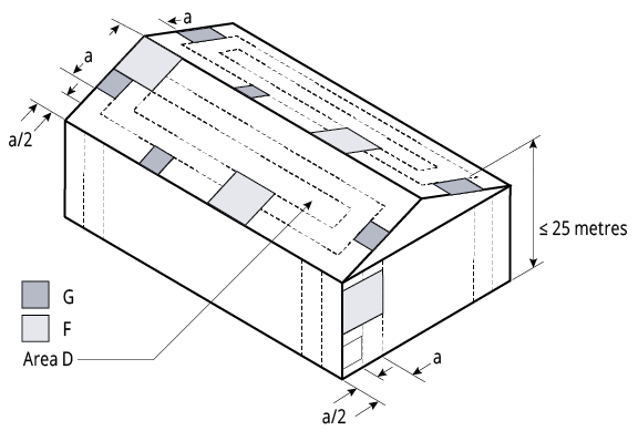
Figure SF CY Local Pressure Factors 002
Note:
The local pressure factors (KL) are shown in Figure SF CY Local Pressure Factors 002 are not applicable at the ridge where the roof pitch is less than 10°. The value of ‘a’ is the minimum of 0.2 breadth, 0.2 width or the height.
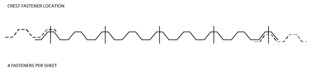
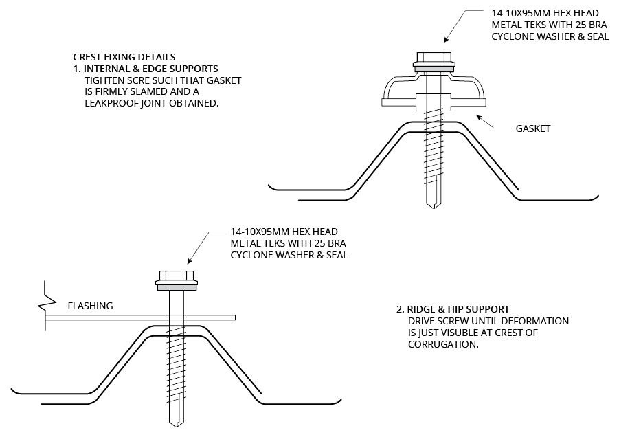
Fixing of Cladding
Fasteners must be selected to match the life expectancy of the cladding material. Recommendations from fastener manufacturers should be sought. Only fasteners complying with AS 3566:2002 and those that are compatible with the roofing material should be used for its fastening.
All fasteners used externally should be fitted with an EPDM seal. Do not use punches to form fastener holes. Fasteners are fixed at alternate crests of the SpanformTM roof sheeting.
Pierce Fixing
Fasteners must be selected to match the life expectancy of the cladding material. Recommendations from fastener manufacturers should be sought.
Only fasteners complying with AS 3566:2002 and those that are compatible with the roofing material should be used for its fastening.
Notes:
All fasteners used externally should be fitted with an EPDM seal (washer). Do not use punches form fastener holes.
Side Lap Fastening
Side lap fasteners may be necessary at mid spans for purlin spacings over 900mm and girt spacings over 1200mm to hold the sheet laps firmly in place and maintain a weather-proof joint. Use 10x16mm Hex Head Tek Screws with Neo washers.
Note:
Do not use punches to form fastener holes.
Insulation
Care needs to be taken when installing insulation with roof sheeting. When insulation thickness up to 50mm are installed the screws detailed in Table SF PF CY 001 may need to be increased depending on the thickness and density of the insulation. When the screw is properly tightened into metal there should be a minimum of three (3) threads protruding past the support being fixed in to. For timber the screw must penetrate the timber as much as the screws detailed in Table SF PF CY 001 do without insulation.
For insulation thicknesses greater than 50mm Fielders® recommend the use of a thermal spacer to help maintain Rw values as well as minimising any bulging in the profile caused by the insulation.
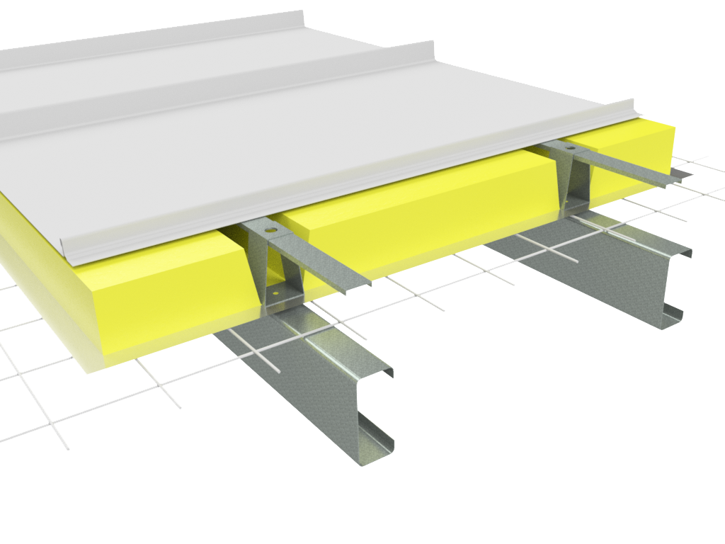
SP INS CY 001
Note:
Image displayed using Shadowline profile
Spanform™ Installation Procedure
For installation procedures see section “Typical Pierce Fix Installation Guide”. For general handling instructions refer to section “Maintenance and Care”.
Turning of Roof Sheeting Ends
Refer to section “Flashings, Cappings & Ends of sheets”.
Curving
For details regarding spring and crank curving of SpanformTM sheets, please see section “Curving of Steel Decks”.
Maximum Sheet Length
See section “Thermal Expansion and Contraction of Steel Sheeting”.
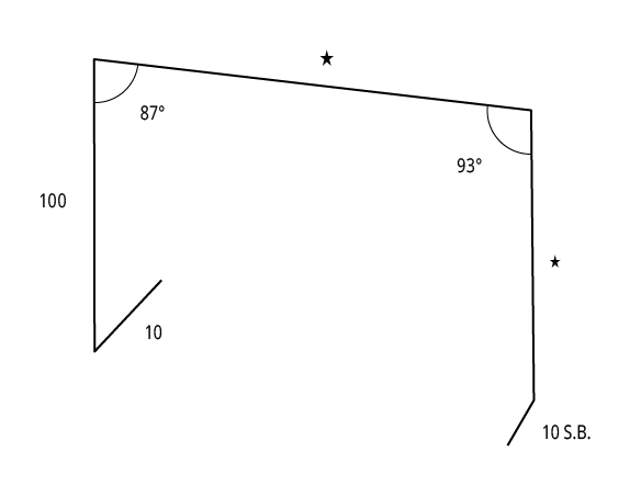
Spanform™ Flashings & Details
Masonry Parapet Side Wall (Low)
Product Code: SF1
Masonry Parapet Side Wall (High)
Product Code: SF2
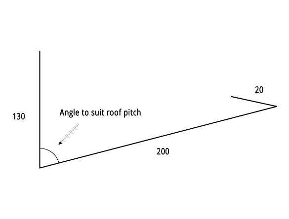
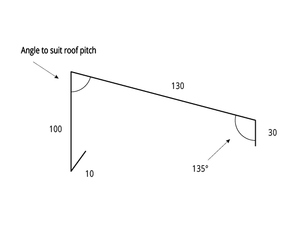
Apron Flashings
Product Code: SF3
GIRTH 330
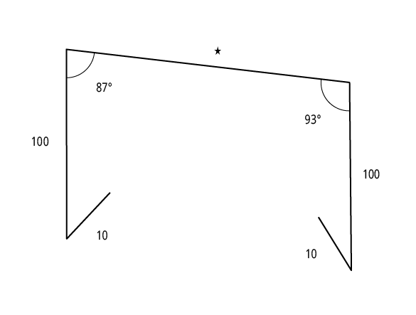
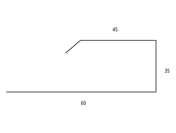
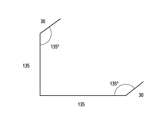
Overflashing
Product Code: SF4
GIRTH 112
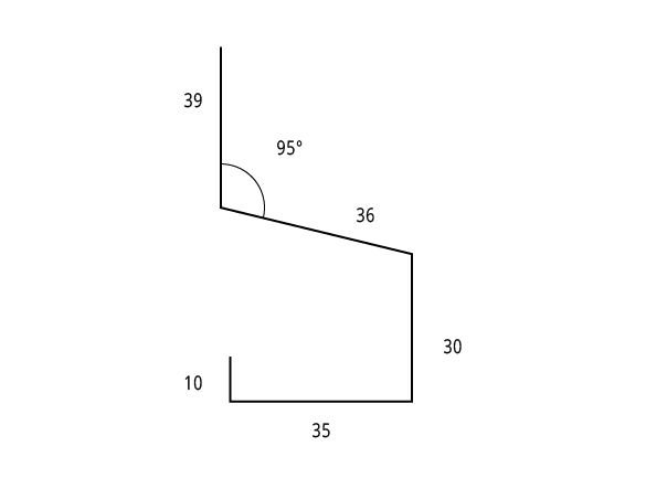
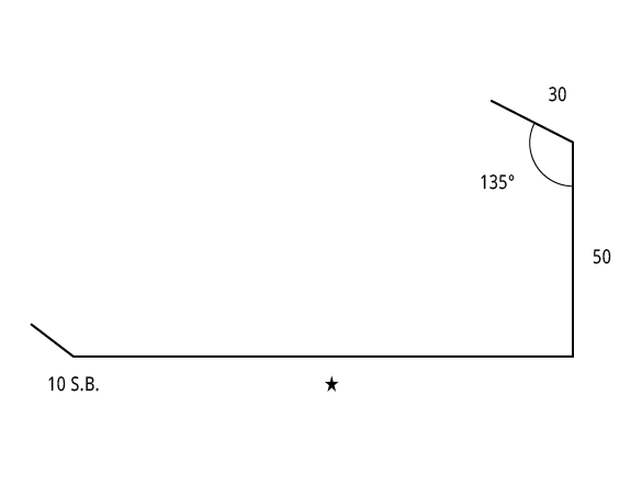
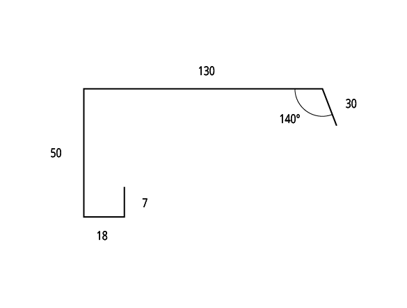
Headwall Apron Flashing
Product Code: SF5
GIRTH 350
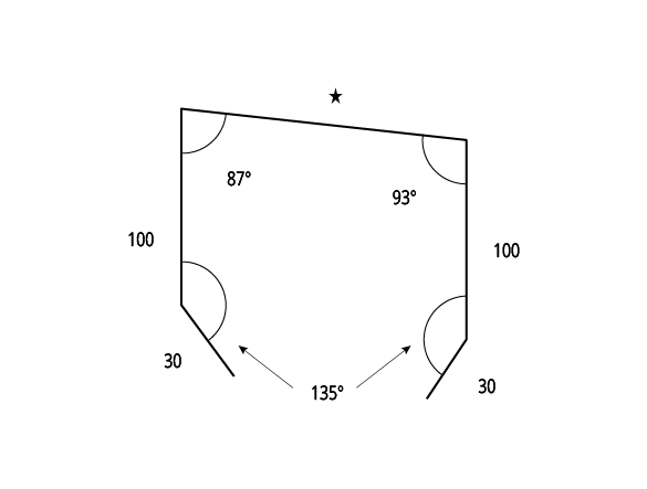
Soaker Gutter
Product Code: SF6
GIRTH 350
Soffit Corner Flashing
Product Code: SF7
GIRTH 149
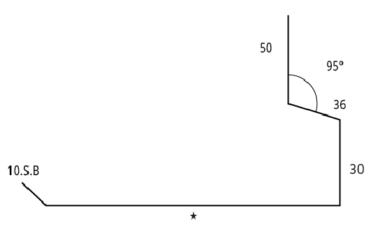
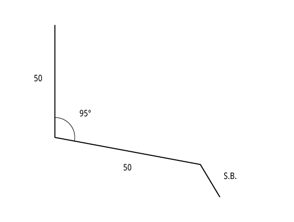
Shoe Flashing
Product Code: SF8
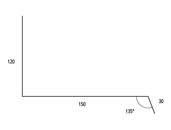
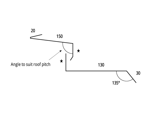
Offset Wall Flashing
Type 1
Product Code: SF9
GIRTH 150
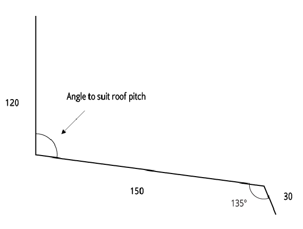
Offset Wall Flashing
Type 2
Product Code: SF10
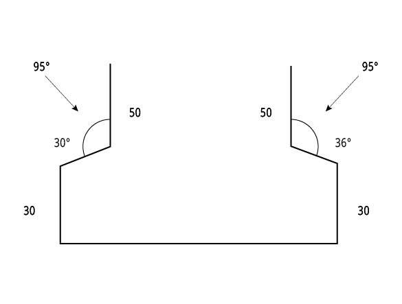
Valley Gutter
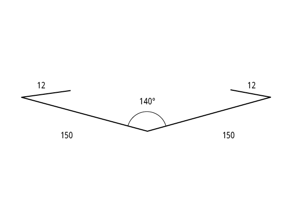
Product Code: SF11
GIRTH 324
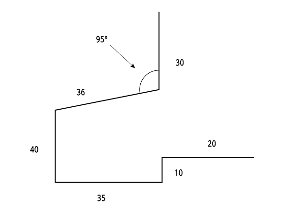
Under Over Flashing
Product Code: SF12
GIRTH 300
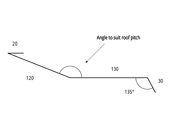
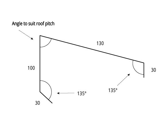
Mansard Roof Flashing
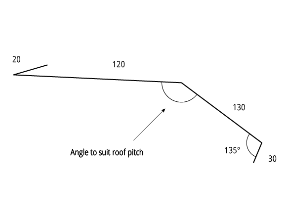
Product Code: SF13
GIRTH 330
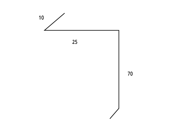
Industrial Door Jamb Flashing
Product Code: SF14
GIRTH 150
Opening Jamb Flashing
Product Code: SF15
Door Head Flashing
Product Code: SF16
GIRTH 100
Apex Capping
Type 1
Product Code: SF17
GIRTH 290
Apex Capping
Type 2
Product Code: SF18
GIRTH 270
Back Channel

Product Code: SF19
GIRTH 110
External Corner & Barge Capping
Product Code: SF20
GIRTH 330
Internal Corner Capping

Product Code: SF21
GIRTH 330
Barge Capping
Product Code: SF22
GIRTH 255
Fragmented Parapet Capping
Product Code: SF23
Two Piece Step Flashing
Product Code: SF24
Table SP FD CY 001
Notes:
1. * denotes size to be determined by application. All sizes are in mm and should be used as a guide only. They should be measured on-site to determine actual size.
2. S.B. denotes ‘Slight Break’.
3. Also refer to “Typical Roofing Details”.