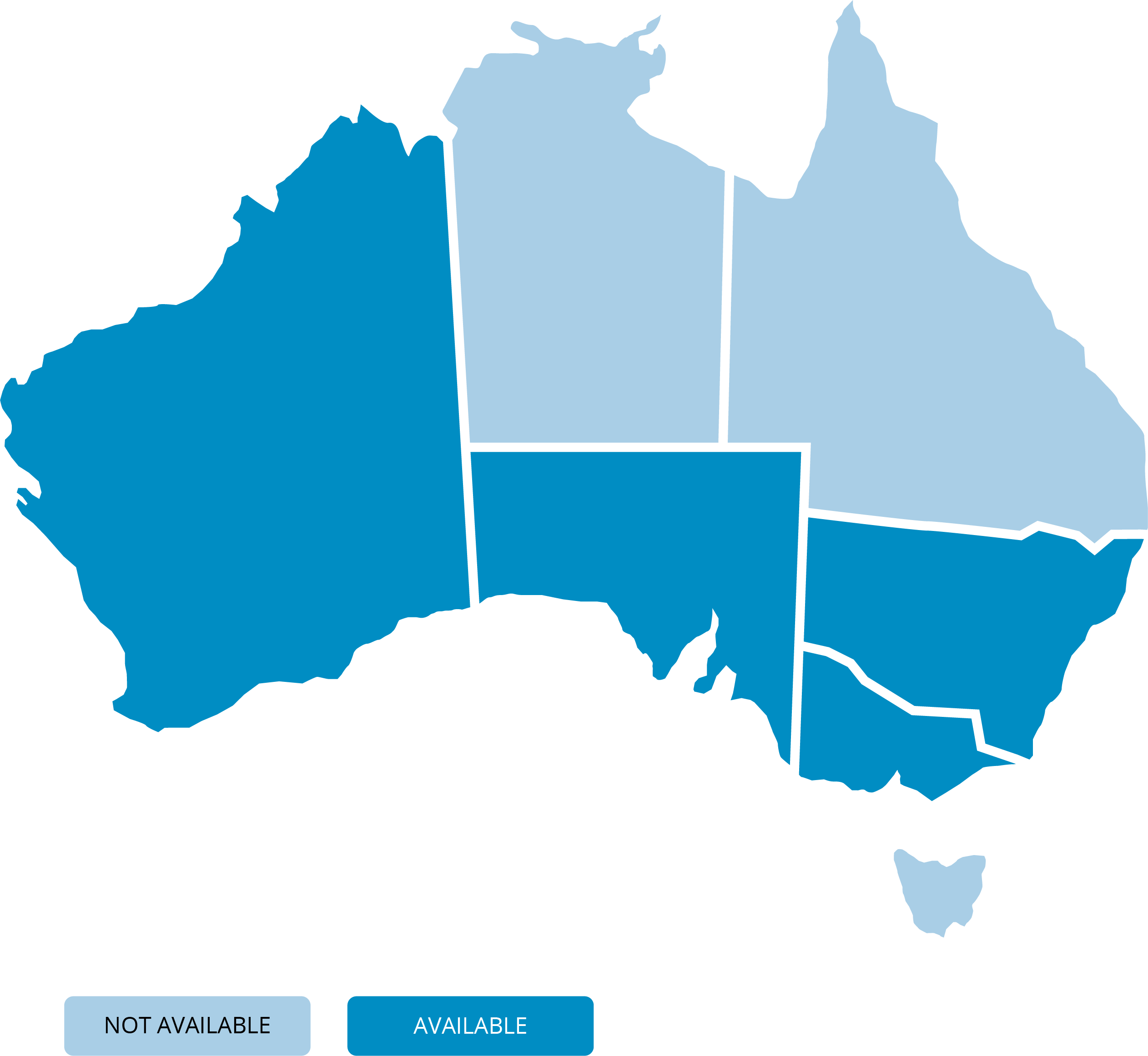
- nsw
- vic
- sa
- wa
You need to select a state...
SK NOTE: I was thinking of putting some placeholder blocks here to indicate there was more content to come (rough example below). But that is being used quite a lot now in apps where content loads automatically - so would be pretty misleading and may lead to a user waiting for something to happen. So still thinking of a better idea here...


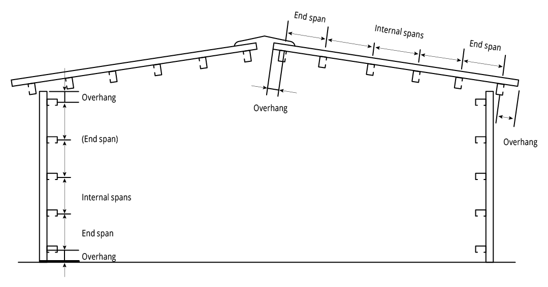
Figure MF NC 001 End Spans, Internal Spans and Overhangs
Pierce Fixing
Fasteners must be selected to match the life expectancy of the cladding material. Recommendations from fastener manufacturers should be sought.
Only fasteners complying with AS 3566:2002 and those that are compatible with the roofing material should be used for its fastening.
Notes:
All fasteners used externally should be fitted with an EPDM seal (washer). Do not use punches to form fastener holes.

Walling Fixing Details - Valley Fixed
6 fasteners per sheet
Figure MF NC 001 End Spans, Internal Spans and Overhangs
Pierce Fixing
Fasteners must be selected to match the life expectancy of the cladding material. Recommendations from fastener manufacturers should be sought.
Only fasteners complying with AS 3566:2002 and those that are compatible with the roofing material should be used for its fastening.
Notes:
All fasteners used externally should be fitted with an EPDM seal (washer). Do not use punches to form fastener holes.