

Figure KF 40 001
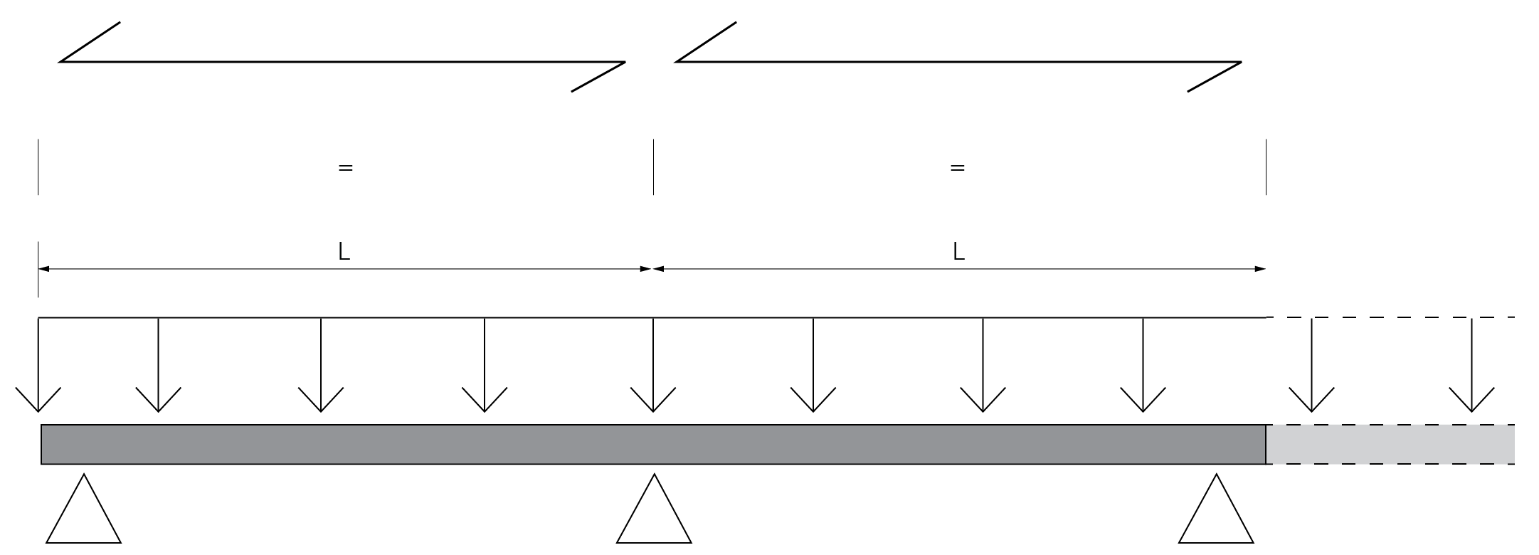
Figure KF 40 002
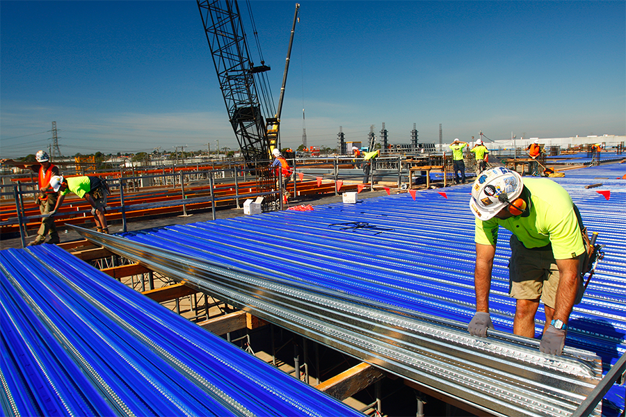
KF40® Pre-stressed / Post-tensioned Slabs
KF40® can be adopted as permanent formwork and composite reinforcement in the design and construction of post-tensioned composite slabs.
The shallow overall depth of the KF40® profile allows post-tensioning tendons to be draped in the spanning and transverse directions of the slab without clashes.
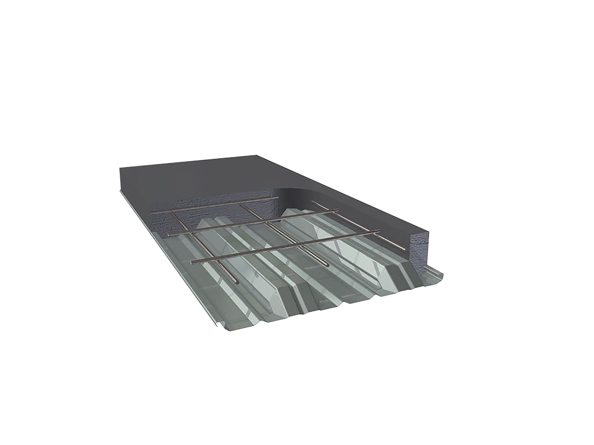
The primary post-tensioning tendons draped parallel to the spanning direction of the KF40® slab are located centrally between ribs at the cover specified in Tables 2A, 2B and 2C to achieve the required FRL.
The minimum recommended post-tensioned slab thickness is 160mm to allow tendons to be draped and pre-stressing anchorages to fit within the slab depth without causing horizontal splitting.
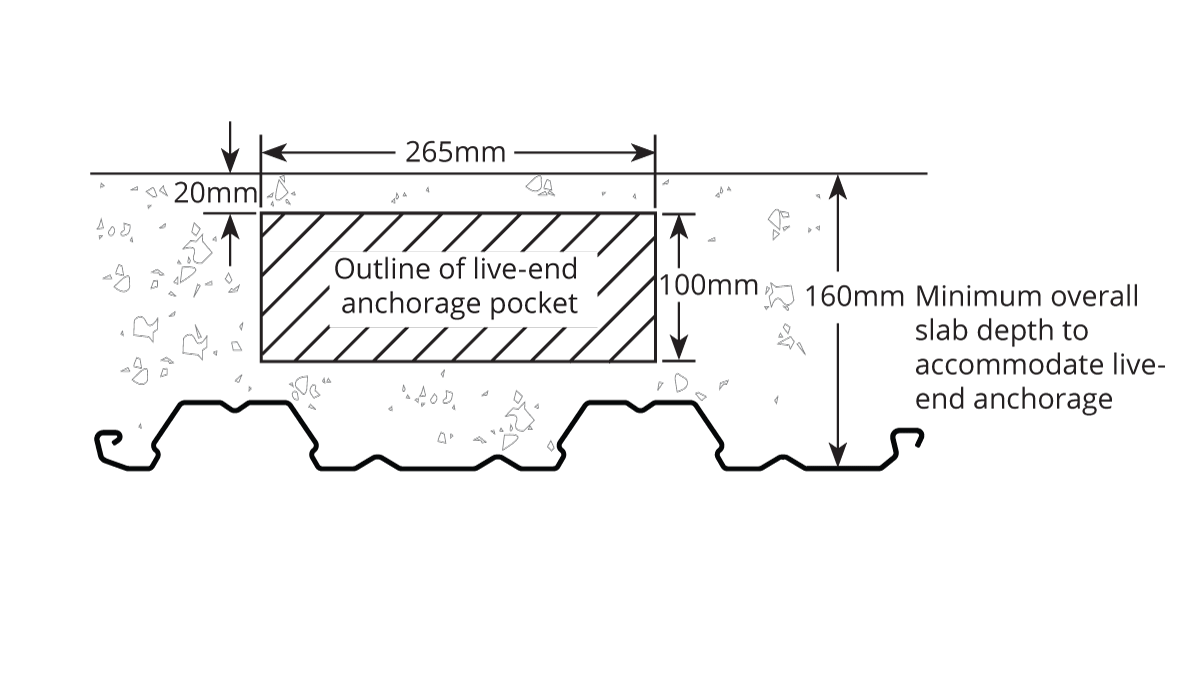
Figure KF 40 003
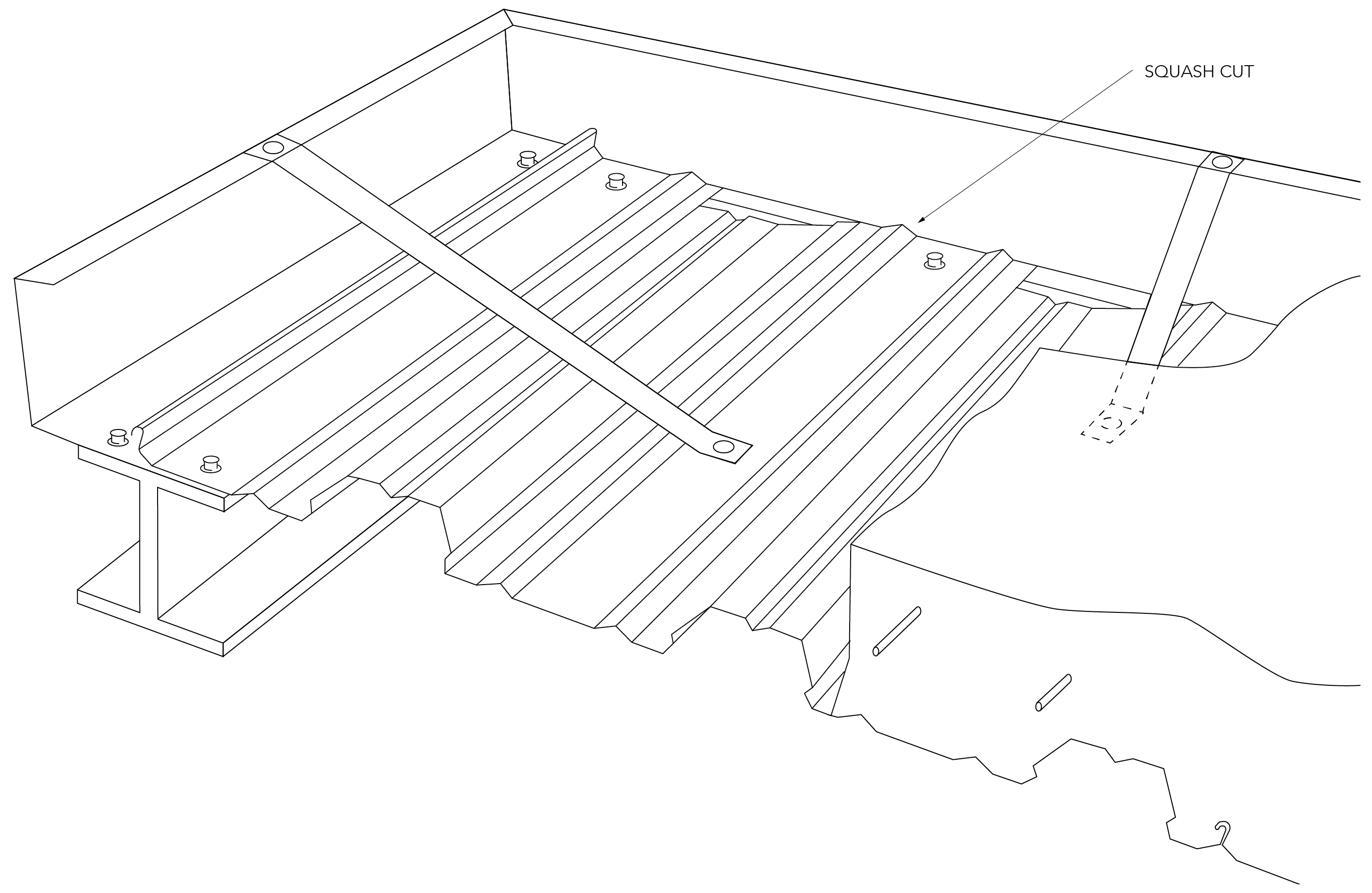
Fitting a Typical Live-End Anchorage in a Composite Slab Incorporating KF40®
Note: Anti-bursting reinforcement can be supported off lap ribs, which ideally are only 20mm high and allow concrete aggregate to pass around the reinforcing bars as necessary.
Locating Longitudinal Tendons
The location of the post-tension tendon for KF40® slabs are determined in order to not exceed the limiting steel temperatures of 450°C (simply supported), 520°C (flat slab) and 650°C (continuous) to ensure consistency with the current version of AS 3600:2009.
For the case of tendons having parallel orientation to the deck it is assumed that the tendon is located centrally between two KF40® ribs. This gives a distance from the centreline of the rib to the edge of the tendon of 85mm. The required distances from the heated soffit to the bottom of the tendon have been determined using TASEF-2 analyses previously undertaken for KF40®.
The slab thickness has been assumed to be 160mm but the results can be considered to be applicable to the range of practical post-tensioned concrete slabs.

Figure KF 40 004
Distances to the Prestressing Tendon.
Locating Transverse Tendons
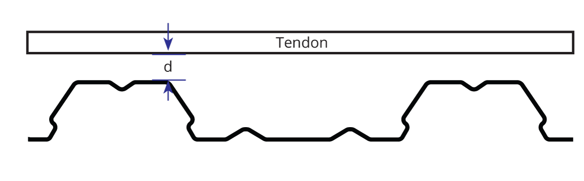
Figure KF 40 005
Distance between Top of Rib and underside of Tendon
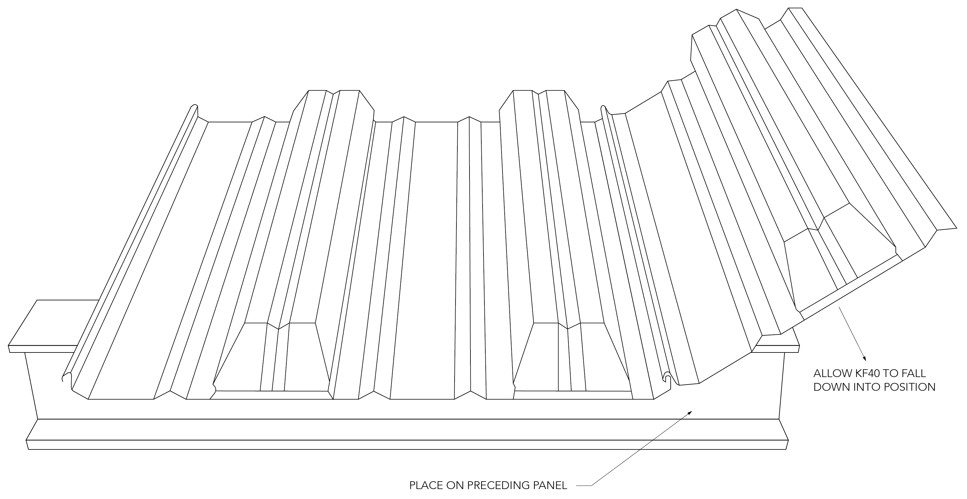
Installing KF40®
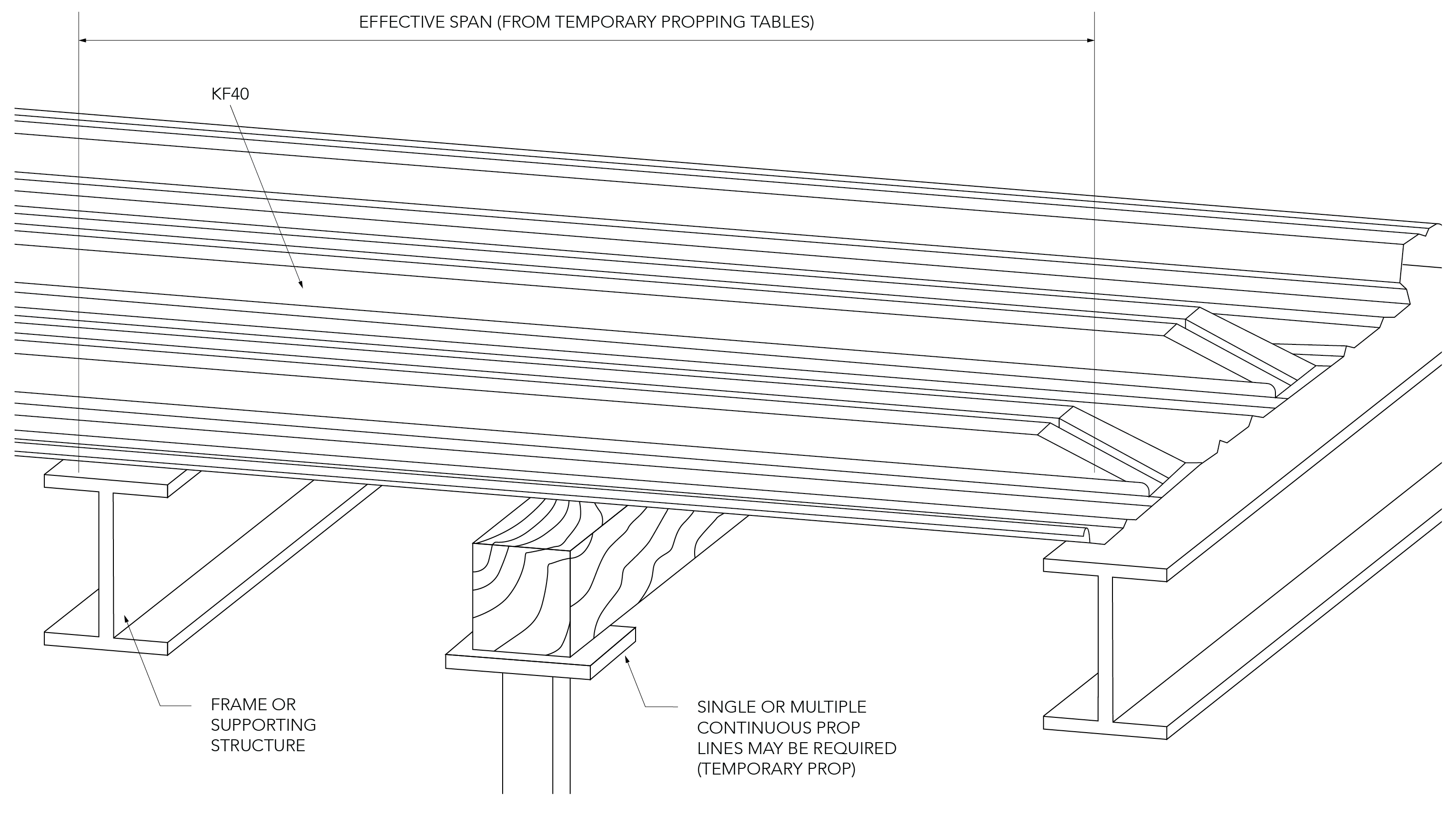
Temporary Propping
If temporary propping is required (refer to the temporary propping tables), props should be placed at the correct centres prior to laying the KF40® sheets. Generally, timber or steel bearers with a minimum dimension of 75mm x 75mm are used on vertical props. The props should be installed so as to prevent settlement during loading by wet concrete and other construction loads.
300mm wide ply strips to be positioned above the header bearers to assist in dispersing the load and minimise any local deformation of the decking due to the headers.
Temporary props should only be removed after the slab has reached sufficient strength (at least 75% of the specified 28 day strength). The full design load may only be applied once the slab has achieved 28-day strength.

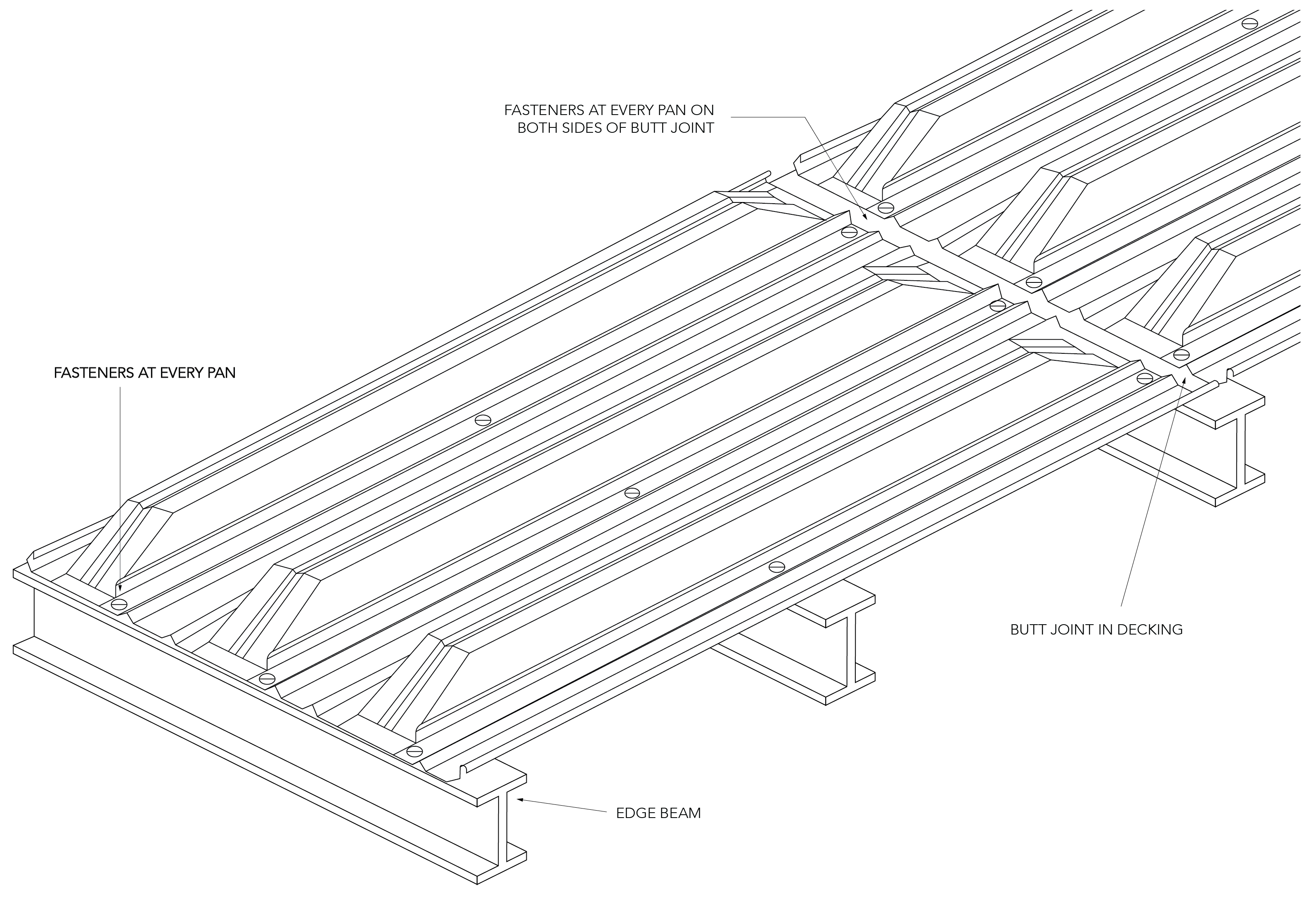
Fastener Locations
The decking must be positively fixed to the supporting structure in order to avoid movement and excessive deflection during the pouring of concrete.
When fixing to a steel support structure, shot fired pins or self- drilling/tapping fasteners should be used. Provide one fastener in each pan at every support.
In the case of other support systems, such as brickwork, block work and concrete, the KF40® sheets must be temporarily held in place against wind and other effects until the concrete is poured.
Edge-form
Galvanised steel edge-forms can be used for the retention of wet concrete to the correct level at the decked floor perimeters. KF40® edge-form is usually shot-fired to the steel support structure or to the KF40® deck and the top of the edge-form is connected back to the decking with restraint straps at approximately 600mm centres using either pop-rivets or self-drilling screws.