Availability
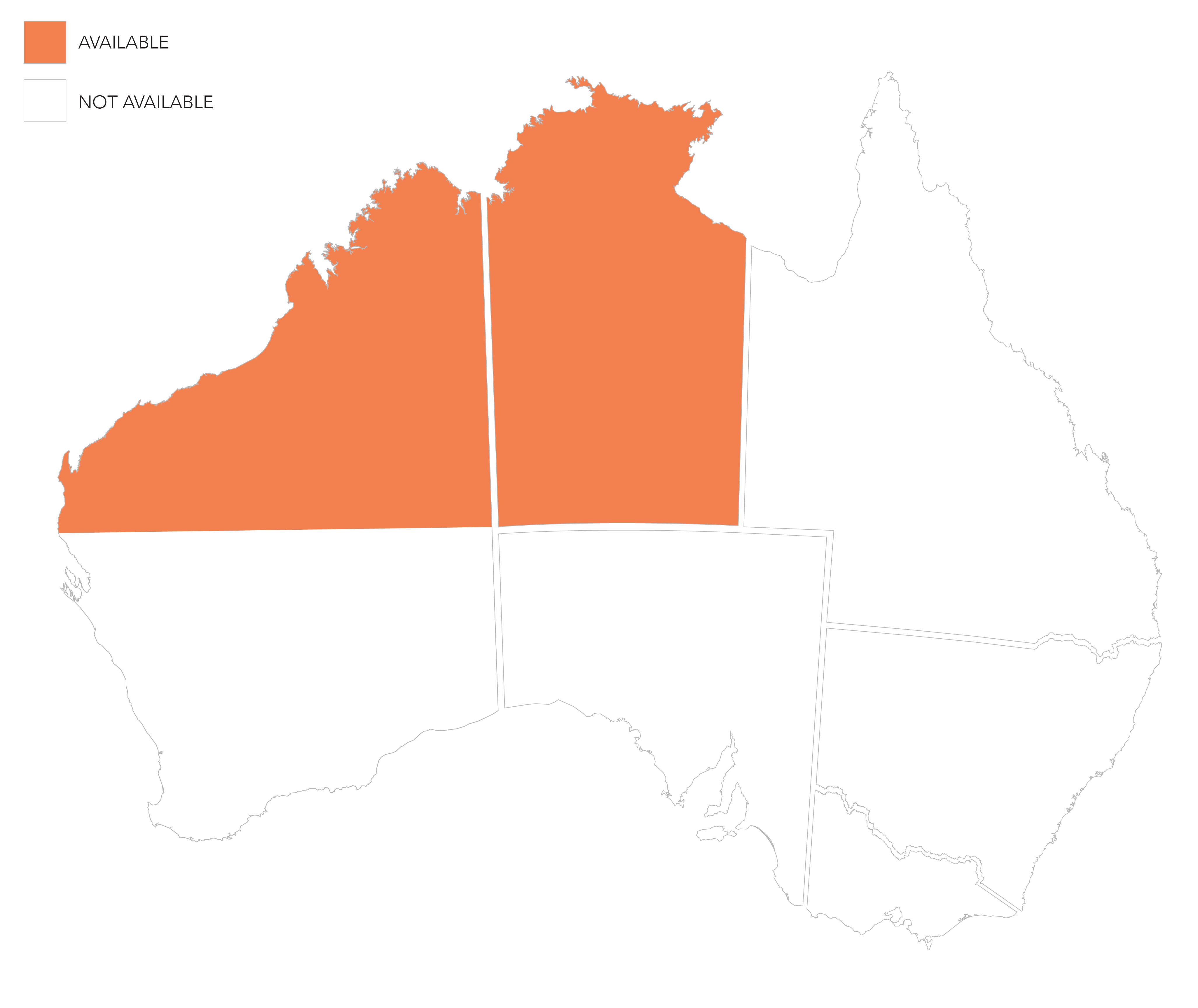
Only produced in Darwin, NT.
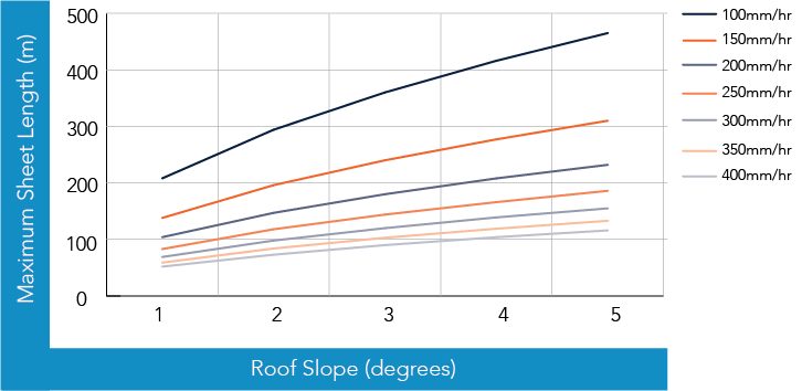
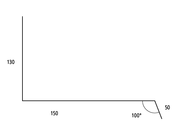
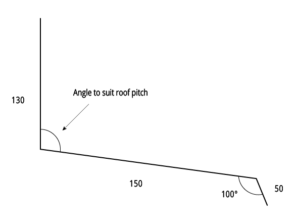
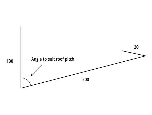
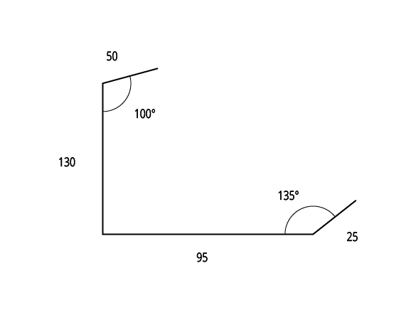
Figure KK RC CY 001
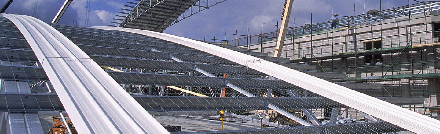
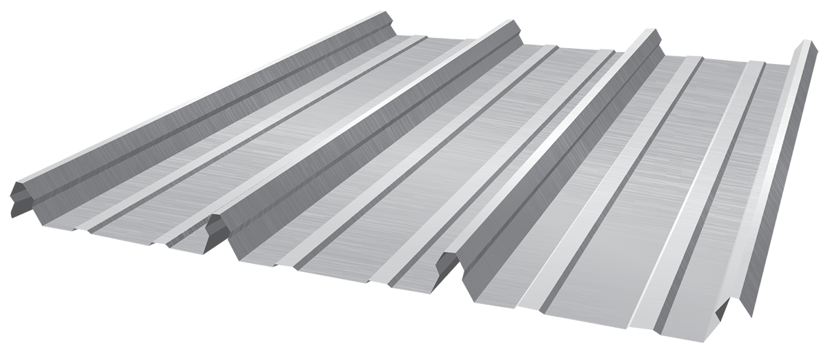
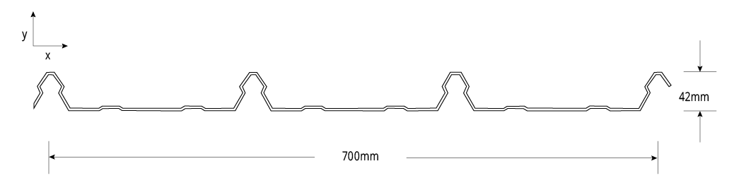
KingKlip 700® Cyclonic Clip Fixed

Mk3 SuperKlip
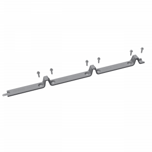
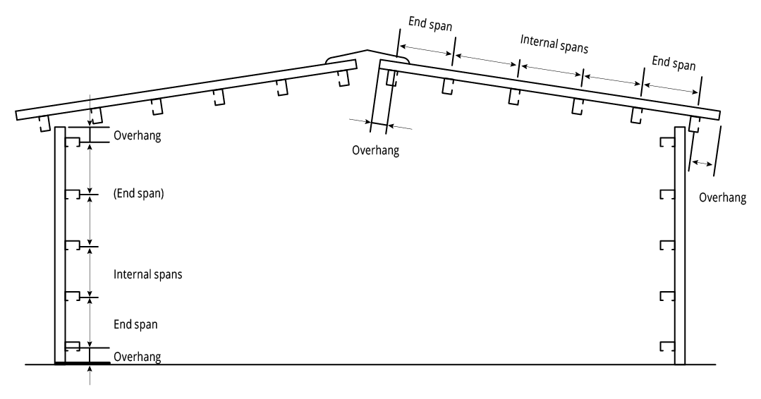
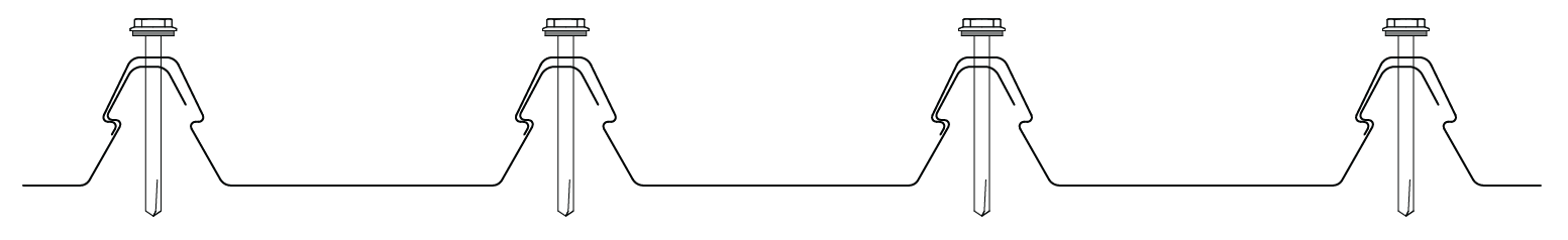
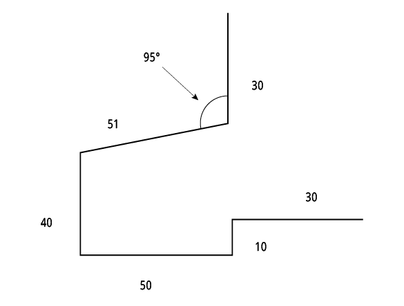
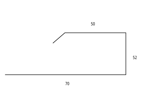
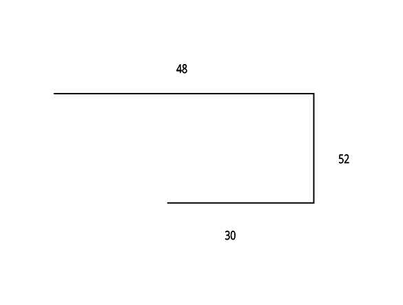
Figure KK CY 004 End Spans, Internal Spans and Overhangs
Cyclonic Load Span Tables: Region C: Clip Fixed
Maximum Allowable Roof Spans* in Region C ≤ 5m
![]()
Maximum Allowable Roof Spans for building heights ≤ 5m: Clip Fixed: 0.42mm BMT
| Terrain Category | Roof Area Notation & Uplift (kPa)* | Single Span (mm) | Double Span (mm) | Multiple Spans (mm) | |
| End | Internal | ||||
| 1 & 2 | D - 4.18 | 1440 | 1450 | 1280 | 1600 |
| F - 5.35 | 1250 | 1210 | 970 | 1230 | |
| G - 6.53 | 1120 | 1020 | - | 920 | |
| 2.5 | D - 3.54 | 1600 | 1630 | 1470 | 1840 |
| F - 4.54 | 1370 | 1370 | 1180 | 1480 | |
| G - 5.54 | 1230 | 1180 | 920 | 1180 | |
Pa,r = 1:500
Va = 66m/s for Region C
Va = 88m/s for Region D
Md = 1.00
Fc = 1.05
Ms = 1.00
External Pressure Coefficient:
Cp,e = -0.9
Internal Pressure Coefficient:
Cp,i = 0.7
Local Pressure Factors:
Kl = 2.0 for Area G and 1.5 for Area F local pressure factors
*Pressure is total ultimate value in accordance with AS1170.2-2011
Table KK RS CY 001A - KingKlip 700® Cyclonic - Region B
Notes:
- Values are based on min. 6 fixings per clip into steel supports with a minimum base metal thickness on 1.5mm.
- Values in italics are estimates based on trend lines fitted to the test data.
- Values are based on installation of safety mesh and 50mm insulation blanket under the sheeting. For insulation thickness greater than 50mm roof spacer systems should be utilised.
Maximum Allowable Roof Spans for building heights ≤ 5m: Clip Fixed: 0.48mm BMT
| Terrain Category | Roof Area Notation & Uplift (kPa)* | Single Span (mm) | Double Span (mm) | Multiple Spans (mm) | |
| End | Internal | ||||
| 1 & 2 | D - 4.18 | 1570 | 1600 | 1400 | 1740 |
| F - 5.35 | 1380 | 1320 | 1100 | 1390 | |
| G - 6.53 | 1220 | 1080 | 850 | 1090 | |
| 2.5 | D - 3.54 | 1710 | 1790 | 1590 | 1980 |
| F - 4.54 | 1510 | 1510 | 1300 | 1620 | |
| G - 5.54 | 1350 | 1280 | 1050 | 1340 | |
Pa,r = 1:500
Va = 66m/s for Region C
Va = 88m/s for Region D
Md = 1.00
Fc = 1.05
Ms = 1.00
External Pressure Coefficient:
Cp,e = -0.9
Internal Pressure Coefficient:
Cp,i = 0.7
Local Pressure Factors:
Kl = 2.0 for Area G and 1.5 for Area F local pressure factors
*Pressure is total ultimate value in accordance with AS1170.2-2011
Table KK RS CY 001B - KingKlip 700® Cyclonic - Region B
Notes:
- Values are based on min 6 fixings per clip into steel supports with a minimum base metal thickness on 1.5mm.
- Values in italics are estimates based on trend lines fitted to the test data.
- Values are based on installation of safety mesh and 50mm insulation blanket under the sheeting. For insulation thickness greater than 50mm roof spacer systems should be utilised.
Maximum Allowable Roof Spans* in Region C 5m-10m
![]()
Maximum Allowable Roof Spans for building heights 5m-10m: Clip Fixed: 0.42mm BMT
| Terrain Category | Roof Area Notation & Uplift (kPa)* | Single Span (mm) | Double Span (mm) | Multiple Spans (mm) | |
| End | Internal | ||||
| 1 & 2 | D - 4.63 | 1360 | 1350 | 1150 | 1450 |
| F - 5.93 | 1180 | 1110 | 830 | 1070 | |
| G - 7.23 | 1050 | 930 | - | 750 | |
| 2.5 | D - 4.13 | 1450 | 1460 | 1290 | 1610 |
| F - 5.30 | 1260 | 1220 | 980 | 1240 | |
| G - 6.46 | 1230 | 1030 | - | 940 | |
Pa,r = 1:500
Va = 66m/s for Region C
Va = 88m/s for Region D
Md = 1.00
Fc = 1.05
Ms = 1.00
External Pressure Coefficient:
Cp,e = -0.9
Internal Pressure Coefficient:
Cp,i = 0.7
Local Pressure Factors:
Kl = 2.0 for Area G and 1.5 for Area F local pressure factors
*Pressure is total ultimate value in accordance with AS1170.2-2011
Table KK RS CY 002A - KingKlip 700® Cyclonic - Region C
Notes:
- Values are based on min 6 fixings per clip into steel supports with a minimum base metal thickness on 1.5mm.
- Values in italics are estimates based on trend lines fitted to the test data.
- Values are based on installation of safety mesh and 50mm insulation blanket under the sheeting. For insulation thickness greater than 50mm roof spacer systems should be utilised.
Maximum Allowable Roof Spans for building heights 5m-10m: Clip Fixed: 0.48mm BMT
| Terrain Category | Roof Area Notation & Uplift (kPa)* | Single Span (mm) | Double Span (mm) | Multiple Spans (mm) | |
| End | Internal | ||||
| 1 & 2 | D - 4.63 | 1490 | 1480 | 1280 | 1590 |
| F - 5.93 | 1300 | 1200 | 980 | 1240 | |
| G - 7.23 | 1140 | 960 | - | 940 | |
| 2.5 | D - 4.13 | 1580 | 1610 | 1410 | 1760 |
| F - 5.30 | 1390 | 1330 | 1120 | 1400 | |
| G - 6.46 | 1230 | 1100 | 870 | 1110 | |
Pa,r = 1:500
Va = 66m/s for Region C
Va = 88m/s for Region D
Md = 1.00
Fc = 1.05
Ms = 1.00
External Pressure Coefficient:
Cp,e = -0.9
Internal Pressure Coefficient:
Cp,i = 0.7
Local Pressure Factors:
Kl = 2.0 for Area G and 1.5 for Area F local pressure factors
*Pressure is total ultimate value in accordance with AS1170.2-2011
Table KK RS CY 002B - KingKlip 700® Cyclonic - Region C
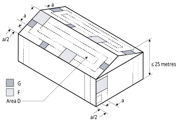
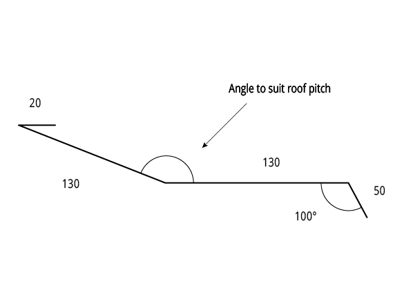
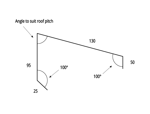
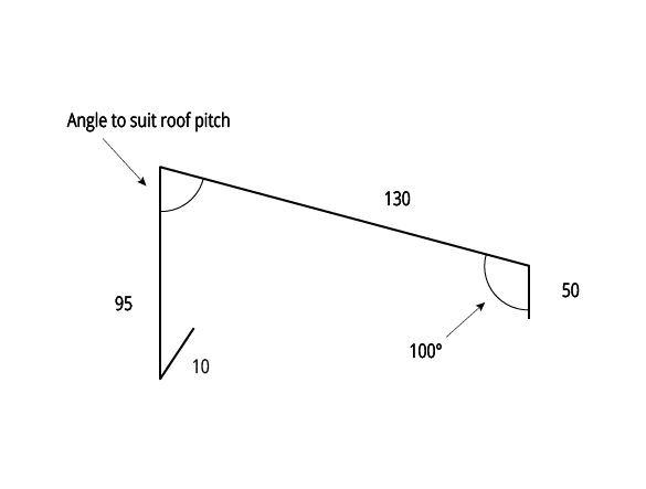
Figure KK CY Local Pressure Factors 003
Note:
1. The value of ‘a’ is the minimum of 0.2 breadth, 0.2 width or 0.2 height.
2. Local pressure factors are not applicable at the ridge where the roof pitch is less than 10°.
KingKlip Screw Fixed
Wind Load Capacity: Strength Limit State Design
Wind Load Capacity: Strength Limit State Design: Screw Fixed: 0.42mm BMT
| Span (mm) | Single Span (kPa) | Double Span (kPa) | Multiple Spans (kPa) | |
| End | Internal | |||
| 900 | 9.35 | 6.18 | 5.05 | - |
| 1200 | 5.83 | 4.58 | 4.01 | 4.89 |
| 1500 | 4.04 | 3.45 | 3.51 | 4.02 |
| 1800 | 2.99 | 2.81 | 2.44 | 3.24 |
| 2100 | - | - | - | 2.57 |
Notes:
- Serviceability pressures can be found in the non-cylonic section.
- Values in italics are estimates based on trend lines fitted to the test data.
Wind Load Capacity: Strength Limit State Design: Screw Fixed: 0.48mm BMT
| Span (mm) | Single Span (kPa) | Double Span (kPa) | Multiple Spans (kPa) | |
| End | Internal | |||
| 900 | - | - | 5.37 | - |
| 1200 | 6.66 | 4.94 | 4.49 | 5.24 |
| 1500 | 4.98 | 4.03 | 3.51 | 4.49 |
| 1800 | 3.75 | 3.21 | 2.44 | 3.71 |
| 2100 | 2.98 | 2.50 | - | 2.89 |
Notes:
- Serviceability pressures can be found in the non-cylonic section.
- Values in italics are estimates based on trend lines fitted to the test data.
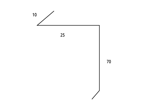
Figure KK CY 004 End Spans, Internal Spans and Overhangs
Maximum Allowable Roof Spans* in Region C ≤ 5m
Maximum Allowable Roof Spans for building heights ≤ 5m: Screw Fixed: 0.42mm BMT
| Terrain Category | Roof Area Notation & Uplift (kPa)* | Single Span (mm) | Double Span (mm) | Multiple Spans (mm) | |
| End | Internal | ||||
| 1 & 2 | D - 4.18 | 1450 | 1250 | 1150 | 1400 |
| F - 5.35 | 1250 | 1000 | 850 | 1050 | |
| G - 6.53 | 1100 | 850 | 600 | 800 | |
| 2.5 | D - 3.54 | 1600 | 1450 | 1400 | 1650 |
| F - 4.54 | 1350 | 1150 | 1050 | 1300 | |
| G - 5.54 | 1200 | 1000 | 800 | 800 | |
Importance Level 2
Maximum Roof Height H = 5, 10m
External Pressure Coefficients:
Cp,e = -0.65 (walling)
Cp,e = -0.90 (roofing)
Internal Pressure Coefficient:
Cpi = 0.7
Local Pressure Factors:
Kl = 2.0, 1.5, 1.0
Ms = Mt = Md = 1.0
Table KK RS CY 005A - KingKlip 700® Cyclonic - Region C
Notes:
- Values are based on fixing into steel supports with a minimum thickness of 1.5mm.
- Values in italics are estimates based on trend lines fitted to the test data.
- Values are based on installation of safety mesh and 50mm insulation blanket under the sheeting. For insulation thickness greater than 50mm roof spacer systems should be utilised.
Maximum Allowable Roof Spans for building heights ≤ 5m: Screw Fixed: 0.48mm BMT
| Terrain Category | Roof Area Notation & Uplift (kPa)* | Single Span (mm) | Double Span (mm) | Multiple Spans (mm) | |
| End | Internal | ||||
| 1 & 2 | D - 4.18 | 1650 | 1400 | 1200 | 1550 |
| F - 5.35 | 1400 | 1100 | 900 | 1150 | |
| G - 6.53 | 1200 | 850 | 700 | 900 | |
| 2.5 | D - 3.54 | 1850 | 1650 | 1400 | 1800 |
| F - 4.54 | 1550 | 1300 | 1100 | 1450 | |
| G - 5.54 | 1350 | 1050 | 900 | 1100 | |
Importance Level 2
Maximum Roof Height H = 5, 10m
External Pressure Coefficients:
Cp,e = -0.65 (walling)
Cp,e = -0.90 (roofing)
Internal Pressure Coefficient:
Cpi = 0.7
Local Pressure Factors:
Kl = 2.0, 1.5, 1.0
Ms = Mt = Md = 1.0
Table KK RS CY 005B - KingKlip 700® Cyclonic - Region C
Notes:
- Values are based on fixing into steel supports with a minimum thickness of 1.5mm.
- Values in italics are estimates based on trend lines fitted to the test data.
- Values are based on installation of safety mesh and 50mm insulation blanket under the sheeting. For insulation thickness greater than 50mm roof spacer systems should be utilised.
Maximum Allowable Roof Spans* in Region C 5m-10m
Maximum Allowable Roof Spans for building heights 5m-10m: Screw Fixed: 0.42mm BMT
| Terrain Category | Roof Area Notation & Uplift (kPa)* | Single Span (mm) | Double Span (mm) | Multiple Spans (mm) | |
| End | Internal | ||||
| 1 & 2 | D - 4.63 | 1350 | 1150 | 1050 | 1250 |
| F - 5.93 | 1150 | 900 | 700 | 900 | |
| G - 7.23 | 1050 | 650 | 500 | 650 | |
| 2.5 | D - 4.13 | 1450 | 1250 | 1200 | 1450 |
| F - 5.30 | 1250 | 1000 | 850 | 1100 | |
| G - 6.46 | 1100 | 850 | 600 | 800 | |
Importance Level 2
Maximum Roof Height H = 5, 10m
External Pressure Coefficients:
Cp,e = -0.65 (walling)
Cp,e = -0.90 (roofing)
Internal Pressure Coefficient:
Cpi = 0.7
Local Pressure Factors:
Kl = 2.0, 1.5, 1.0
Ms = Mt = Md = 1.0
Table KK RS CY 006A - KingKlip 700® Cyclonic - Region C
Notes:
- Values are based on fixing into steel supports with a minimum thickness of 1.5mm.
- Values in italics are estimates based on trend lines fitted to the test data.
- Values are based on installation of safety mesh and 50mm insulation blanket under the sheeting. For insulation thickness greater than 50mm roof spacer systems should be utilised.
Maximum Allowable Roof Spans for building heights 5m-10m: Screw Fixed: 0.48mm BMT
| Terrain Category | Roof Area Notation & Uplift (kPa)* | Single Span (mm) | Double Span (mm) | Multiple Spans (mm) | |
| End | Internal | ||||
| 1 & 2 | D - 4.63 | 1550 | 1300 | 1100 | 1400 |
| F - 5.93 | 1300 | 950 | 800 | 1000 | |
| G - 7.23 | 1100 | 700 | 600 | 750 | |
| 2.5 | D - 4.13 | 1650 | 1450 | 1250 | 1600 |
| F - 5.30 | 1400 | 1100 | 950 | 1200 | |
| G - 6.46 | 1200 | 850 | 700 | 900 | |
Importance Level 2
Maximum Roof Height H = 5, 10m
External Pressure Coefficients:
Cp,e = -0.65 (walling)
Cp,e = -0.90 (roofing)
Internal Pressure Coefficient:
Cpi = 0.7
Local Pressure Factors:
Kl = 2.0, 1.5, 1.0
Ms = Mt = Md = 1.0
Table KK RS CY 006B - KingKlip 700® Cyclonic - Region C
Notes:
- Values are based on fixing into steel supports with a minimum thickness of 1.5mm.
- Values in italics are estimates based on trend lines fitted to the test data.
- Values are based on installation of safety mesh and 50mm insulation blanket under the sheeting. For insulation thickness greater than 50mm roof spacer systems should be utilised.
Maximum Allowable Wall Spans* in Region C ≤ 5m
Maximum Allowable Wall Spans for building heights ≤ 5m: Screw Fixed: 0.42mm BMT
| Terrain Category | Roof Area Notation & Uplift (kPa)* | Single Span (mm) | Double Span (mm) | Multiple Spans (mm) | |
| End | Internal | ||||
| 1 & 2 | D - 4.18 | 1600 | 1400 | 1400 | 1650 |
| F - 5.35 | 1400 | 1200 | 1100 | 1350 | |
| G - 6.53 | 1250 | 1000 | 850 | 1100 | |
| 2.5 | D - 3.54 | 1800 | 1550 | 1650 | 1900 |
| F - 4.54 | 1550 | 1300 | 1350 | 1600 | |
| G - 5.54 | 1400 | 1150 | 1100 | 1350 | |
Importance Level 2
Maximum Roof Height H = 5, 10m
External Pressure Coefficients:
Cp,e = -0.65 (walling)
Cp,e = -0.90 (roofing)
Internal Pressure Coefficient:
Cpi = 0.7
Local Pressure Factors:
Kl = 2.0, 1.5, 1.0
Ms = Mt = Md = 1.0
Table KK WS CY 005A - KingKlip 700® Cyclonic - Region C
Notes:
- Values are based on fixing into steel supports with a minimum thickness of 1.5mm.
- Values in italics are estimates based on trend lines fitted to the test data.
- Values are based on installation of safety mesh and 50mm insulation blanket under the sheeting. For insulation thickness greater than 50mm roof spacer systems should be utilised.
Maximum Allowable Wall Spans for building heights ≤ 5m: Screw Fixed: 0.48mm BMT
| Terrain Category | Roof Area Notation & Uplift (kPa)* | Single Span (mm) | Double Span (mm) | Multiple Spans (mm) | |
| End | Internal | ||||
| 1 & 2 | D - 4.18 | 1850 | 1600 | 1450 | 1850 |
| F - 5.35 | 1600 | 1350 | 1150 | 1500 | |
| G - 6.53 | 1400 | 1100 | 950 | 1200 | |
| 2.5 | D - 3.54 | 2100 | 1850 | 1650 | 2050 |
| F - 4.54 | 1800 | 1600 | 1350 | 1750 | |
| G - 5.54 | 1600 | 1350 | 1150 | 1450 | |
Importance Level 2
Maximum Roof Height H = 5, 10m
External Pressure Coefficients:
Cp,e = -0.65 (walling)
Cp,e = -0.90 (roofing)
Internal Pressure Coefficient:
Cpi = 0.7
Local Pressure Factors:
Kl = 2.0, 1.5, 1.0
Ms = Mt = Md = 1.0
Table KK WS CY 005B - KingKlip 700® Cyclonic - Region C
Notes:
- Values are based on fixing into steel supports with a minimum thickness of 1.5mm.
- Values in italics are estimates based on trend lines fitted to the test data.
- Values are based on installation of safety mesh and 50mm insulation blanket under the sheeting. For insulation thickness greater than 50mm roof spacer systems should be utilised.
Maximum Allowable Wall Spans* in Region C 5m-10m
Maximum Allowable Wall Spans for building heights 5m-10m: Screw Fixed: 0.42mm BMT
| Terrain Category | Roof Area Notation & Uplift (kPa)* | Single Span (mm) | Double Span (mm) | Multiple Spans (mm) | |
| End | Internal | ||||
| 1 & 2 | D - 4.63 | 1500 | 1350 | 1250 | 1500 |
| F - 5.93 | 1300 | 1100 | 950 | 1200 | |
| G - 7.23 | 1200 | 950 | 750 | 950 | |
| 2.5 | D - 4.13 | 1600 | 1500 | 1400 | 1650 |
| F - 5.30 | 1400 | 1200 | 1100 | 1350 | |
| G - 6.46 | 1250 | 1050 | 900 | 1100 | |
Importance Level 2
Maximum Roof Height H = 5, 10m
External Pressure Coefficients:
Cp,e = -0.65 (walling)
Cp,e = -0.90 (roofing)
Internal Pressure Coefficient:
Cpi = 0.7
Local Pressure Factors:
Kl = 2.0, 1.5, 1.0
Ms = Mt = Md = 1.0
Table KK WS CY 006A - KingKlip 700® Cyclonic - Region C
Notes:
- Values are based on fixing into steel supports with a minimum thickness of 1.5mm.
- Values in italics are estimates based on trend lines fitted to the test data.
- Values are based on installation of safety mesh and 50mm insulation blanket under the sheeting. For insulation thickness greater than 50mm roof spacer systems should be utilised.
Maximum Allowable Wall Spans for building heights 5m-10m: Screw Fixed: 0.48mm BMT
| Terrain Category | Roof Area Notation & Uplift (kPa)* | Single Span (mm) | Double Span (mm) | Multiple Spans (mm) | |
| End | Internal | ||||
| 1 & 2 | D - 4.63 | 1750 | 1500 | 1300 | 1650 |
| F - 5.93 | 1500 | 1200 | 1050 | 1300 | |
| G - 7.23 | 1300 | 1000 | 800 | 1050 | |
| 2.5 | D - 4.13 | 1850 | 1650 | 1450 | 1850 |
| F - 5.30 | 1600 | 1350 | 1150 | 1500 | |
| G - 6.46 | 1400 | 1150 | 950 | 1250 | |
Importance Level 2
Maximum Roof Height H = 5, 10m
External Pressure Coefficients:
Cp,e = -0.65 (walling)
Cp,e = -0.90 (roofing)
Internal Pressure Coefficient:
Cpi = 0.7
Local Pressure Factors:
Kl = 2.0, 1.5, 1.0
Ms = Mt = Md = 1.0
Table KK WS CY 006B - KingKlip 700® Cyclonic - Region C
Notes:
- Values are based on fixing into steel supports with a minimum thickness of 1.5mm.
- Values in italics are estimates based on trend lines fitted to the test data.
- Values are based on installation of safety mesh and 50mm insulation blanket under the sheeting. For insulation thickness greater than 50mm roof spacer systems should be utilised.
Maximum Allowable Roof Spans* in Region D ≤ 5m
Maximum Allowable Roof Spans for building heights ≤ 5m: Screw Fixed: 0.42mm BMT
| Terrain Category | Roof Area Notation & Uplift (kPa)* | Single Span (mm) | Double Span (mm) | Multiple Spans (mm) | |
| End | Internal | ||||
| 1 & 2 | D - 6.66 | 1100 | 850 | 600 | 750 |
| F - 8.54 | 950 | 650 | 350 | 500 | |
| G - 10.41 | 800 | 550 | - | 300 | |
| 2.5 | D - 5.65 | 1200 | 950 | 750 | 1000 |
| F - 7.24 | 1050 | 750 | 500 | 650 | |
| G - 8.83 | 900 | 650 | 300 | 450 | |
Importance Level 2
Maximum Roof Height H = 5, 10m
External Pressure Coefficients:
Cp,e = -0.65 (walling)
Cp,e = -0.90 (roofing)
Internal Pressure Coefficient:
Cpi = 0.7
Local Pressure Factors:
Kl = 2.0, 1.5, 1.0
Ms = Mt = Md = 1.0
Table KK RS CY 007A - KingKlip 700® Cyclonic - Region D
Notes:
- Values are based on fixing into steel supports with a minimum thickness of 1.5mm.
- Values in italics are estimates based on trend lines fitted to the test data.
- Values are based on installation of safety mesh and 50mm insulation blanket under the sheeting. For insulation thickness greater than 50mm roof spacer systems should be utilised.
Maximum Allowable Roof Spans for building heights ≤ 5m: Screw Fixed: 0.48mm BMT
| Terrain Category | Roof Area Notation & Uplift (kPa)* | Single Span (mm) | Double Span (mm) | Multiple Spans (mm) | |
| End | Internal | ||||
| 1 & 2 | D - 6.66 | 1200 | 800 | 650 | 850 |
| F - 8.54 | 1000 | 450 | 400 | 550 | |
| G - 10.41 | 850 | - | - | 350 | |
| 2.5 | D - 5.65 | 1350 | 1000 | 850 | 1100 |
| F - 7.24 | 1100 | 700 | 600 | 750 | |
| G - 8.83 | 1000 | 450 | 400 | 500 | |
Importance Level 2
Maximum Roof Height H = 5, 10m
External Pressure Coefficients:
Cp,e = -0.65 (walling)
Cp,e = -0.90 (roofing)
Internal Pressure Coefficient:
Cpi = 0.7
Local Pressure Factors:
Kl = 2.0, 1.5, 1.0
Ms = Mt = Md = 1.0
Table KK RS CY 007B - KingKlip 700® Cyclonic - Region D
Notes:
- Values are based on fixing into steel supports with a minimum thickness of 1.5mm.
- Values in italics are estimates based on trend lines fitted to the test data.
- Values are based on installation of safety mesh and 50mm insulation blanket under the sheeting. For insulation thickness greater than 50mm roof spacer systems should be utilised.
Maximum Allowable Roof Spans* in Region D 5m-10m
Maximum Allowable Roof Spans for building heights 5m-10m: Screw Fixed: 0.42mm BMT
| Terrain Category | Roof Area Notation & Uplift (kPa)* | Single Span (mm) | Double Span (mm) | Multiple Spans (mm) | |
| End | Internal | ||||
| 1 & 2 | D - 7.38 | 1000 | 750 | 450 | 1250 |
| F - 9.46 | 900 | 600 | - | 900 | |
| G - 11.54 | 750 | 500 | - | 650 | |
| 2.5 | D - 6.59 | 1100 | 850 | 600 | 1450 |
| F - 8.45 | 950 | 650 | 350 | 1050 | |
| G - 10.30 | 850 | 550 | - | 800 | |
Importance Level 2
Maximum Roof Height H = 5, 10m
External Pressure Coefficients:
Cp,e = -0.65 (walling)
Cp,e = -0.90 (roofing)
Internal Pressure Coefficient:
Cpi = 0.7
Local Pressure Factors:
Kl = 2.0, 1.5, 1.0
Ms = Mt = Md = 1.0
Table KK RS CY 008A - KingKlip 700® Cyclonic - Region D
Notes:
- Values are based on fixing into steel supports with a minimum thickness of 1.5mm.
- Values in italics are estimates based on trend lines fitted to the test data.
- Values are based on installation of safety mesh and 50mm insulation blanket under the sheeting. For insulation thickness greater than 50mm roof spacer systems should be utilised.
Maximum Allowable Roof Spans for building heights 5m-10m: Screw Fixed: 0.48mm BMT
| Terrain Category | Roof Area Notation & Uplift (kPa)* | Single Span (mm) | Double Span (mm) | Multiple Spans (mm) | |
| End | Internal | ||||
| 1 & 2 | D - 7.38 | 1100 | 650 | 550 | 700 |
| F - 9.46 | 950 | 350 | 350 | 400 | |
| G - 11.54 | 800 | - | - | - | |
| 2.5 | D - 6.59 | 1200 | 800 | 700 | 850 |
| F - 8.45 | 1000 | 500 | 450 | 550 | |
| G - 10.30 | 900 | - | - | 350 | |
Importance Level 2
Maximum Roof Height H = 5, 10m
External Pressure Coefficients:
Cp,e = -0.65 (walling)
Cp,e = -0.90 (roofing)
Internal Pressure Coefficient:
Cpi = 0.7
Local Pressure Factors:
Kl = 2.0, 1.5, 1.0
Ms = Mt = Md = 1.0
Table KK RS CY 008B - KingKlip 700® Cyclonic - Region D
Notes:
- Values are based on fixing into steel supports with a minimum thickness of 1.5mm.
- Values in italics are estimates based on trend lines fitted to the test data.
- Values are based on installation of safety mesh and 50mm insulation blanket under the sheeting. For insulation thickness greater than 50mm roof spacer systems should be utilised.
Maximum Allowable Wall Spans* in Region D ≤ 5m
Maximum Allowable Wall Spans for building heights ≤ 5m: Screw Fixed: 0.42mm BMT
| Terrain Category | Roof Area Notation & Uplift (kPa)* | Single Span (mm) | Double Span (mm) | Multiple Spans (mm) | |
| End | Internal | ||||
| 1 & 2 | D - 6.66 | 1200 | 950 | 800 | 1000 |
| F - 8.54 | 1050 | 800 | 550 | 700 | |
| G - 10.41 | 950 | 700 | 350 | 500 | |
| 2.5 | D - 5.65 | 1350 | 1100 | 1000 | 1200 |
| F - 7.24 | 1150 | 900 | 700 | 900 | |
| G - 8.83 | 1050 | 800 | 500 | 700 | |
Importance Level 2
Maximum Roof Height H = 5, 10m
External Pressure Coefficients:
Cp,e = -0.65 (walling)
Cp,e = -0.90 (roofing)
Internal Pressure Coefficient:
Cpi = 0.7
Local Pressure Factors:
Kl = 2.0, 1.5, 1.0
Ms = Mt = Md = 1.0
Table KK WS CY 007A - KingKlip 700® Cyclonic - Region D
Notes:
- Values are based on fixing into steel supports with a minimum thickness of 1.5mm.
- Values in italics are estimates based on trend lines fitted to the test data.
- Values are based on installation of safety mesh and 50mm insulation blanket under the sheeting. For insulation thickness greater than 50mm roof spacer systems should be utilised.
Maximum Allowable Wall Spans for building heights ≤ 5m: Screw Fixed: 0.48mm BMT
| Terrain Category | Roof Area Notation & Uplift (kPa)* | Single Span (mm) | Double Span (mm) | Multiple Spans (mm) | |
| End | Internal | ||||
| 1 & 2 | D - 6.66 | 1350 | 1050 | 850 | 1100 |
| F - 8.54 | 1150 | 750 | 600 | 800 | |
| G - 10.41 | 1000 | 500 | 450 | 550 | |
| 2.5 | D - 5.65 | 1500 | 1250 | 1050 | 1300 |
| F - 7.24 | 1300 | 950 | 800 | 1050 | |
| G - 8.83 | 1150 | 750 | 600 | 750 | |
Importance Level 2
Maximum Roof Height H = 5, 10m
External Pressure Coefficients:
Cp,e = -0.65 (walling)
Cp,e = -0.90 (roofing)
Internal Pressure Coefficient:
Cpi = 0.7
Local Pressure Factors:
Kl = 2.0, 1.5, 1.0
Ms = Mt = Md = 1.0
Table KK WS CY 007B - KingKlip 700® Cyclonic - Region D
Notes:
- Values are based on fixing into steel supports with a minimum thickness of 1.5mm.
- Values in italics are estimates based on trend lines fitted to the test data.
- Values are based on installation of safety mesh and 50mm insulation blanket under the sheeting. For insulation thickness greater than 50mm roof spacer systems should be utilised.
Maximum Allowable Wall Spans* in Region D 5m-10m
Maximum Allowable Wall Spans for building heights 5m-10m: Screw Fixed: 0.42mm BMT
| Terrain Category | Roof Area Notation & Uplift (kPa)* | Single Span (mm) | Double Span (mm) | Multiple Spans (mm) | |
| End | Internal | ||||
| 1 & 2 | D - 7.38 | 1150 | 900 | 650 | 850 |
| F - 9.46 | 1000 | 750 | 400 | 600 | |
| G - 11.54 | 900 | 600 | - | 400 | |
| 2.5 | D - 6.59 | 1200 | 1000 | 800 | 1000 |
| F - 8.45 | 1050 | 800 | 550 | 700 | |
| G - 10.30 | 950 | 700 | 350 | 500 | |
Importance Level 2
Maximum Roof Height H = 5, 10m
External Pressure Coefficients:
Cp,e = -0.65 (walling)
Cp,e = -0.90 (roofing)
Internal Pressure Coefficient:
Cpi = 0.7
Local Pressure Factors:
Kl = 2.0, 1.5, 1.0
Ms = Mt = Md = 1.0
Table KK WS CY 008A - KingKlip 700® Cyclonic - Region D
Notes:
- Values are based on fixing into steel supports with a minimum thickness of 1.5mm.
- Values in italics are estimates based on trend lines fitted to the test data.
- Values are based on installation of safety mesh and 50mm insulation blanket under the sheeting. For insulation thickness greater than 50mm roof spacer systems should be utilised.
Maximum Allowable Wall Spans for building heights 5m-10m: Screw Fixed: 0.48mm BMT
| Terrain Category | Roof Area Notation & Uplift (kPa)* | Single Span (mm) | Double Span (mm) | Multiple Spans (mm) | |
| End | Internal | ||||
| 1 & 2 | D - 7.38 | 1250 | 900 | 750 | 950 |
| F - 9.46 | 1050 | 600 | 500 | 650 | |
| G - 11.54 | 950 | 350 | 350 | 450 | |
| 2.5 | D - 6.59 | 1350 | 1050 | 850 | 1100 |
| F - 8.45 | 1150 | 750 | 600 | 800 | |
| G - 10.30 | 1000 | 500 | 450 | 600 | |
Importance Level 2
Maximum Roof Height H = 5, 10m
External Pressure Coefficients:
Cp,e = -0.65 (walling)
Cp,e = -0.90 (roofing)
Internal Pressure Coefficient:
Cpi = 0.7
Local Pressure Factors:
Kl = 2.0, 1.5, 1.0
Ms = Mt = Md = 1.0
Table KK WS CY 008B - KingKlip 700® Cyclonic - Region D
Notes:
- Values are based on fixing into steel supports with a minimum thickness of 1.5mm.
- Values in italics are estimates based on trend lines fitted to the test data.
- Values are based on installation of safety mesh and 50mm insulation blanket under the sheeting. For insulation thickness greater than 50mm roof spacer systems should be utilised.
Figure KK CY Local Pressure Factors 003
Note:
1. The value of ‘a’ is the minimum of 0.2 breadth, 0.2 width or 0.2 height.
2. Local pressure factors are not applicable at the ridge where the roof pitch is less than 10°.
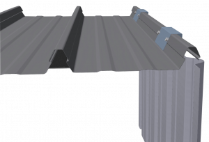
Figure KK CY 005 Mk3 SuperKlip KingKlip® Clip Fix Clipping System
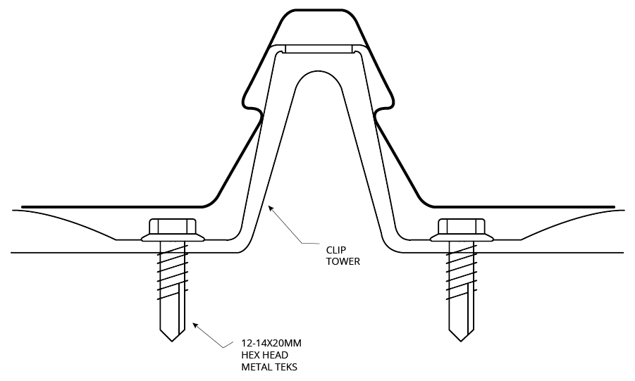
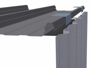
Figure KK CY Clip Fixing Detail 006
Notes:
1. Use six (6) fasteners per clip.
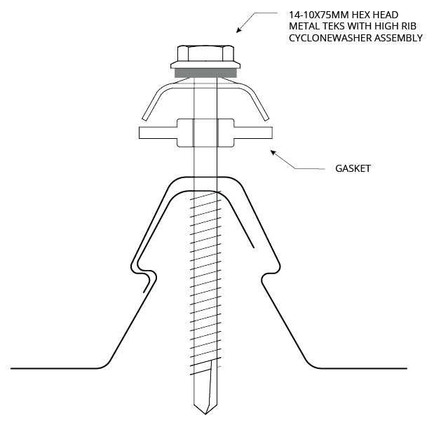
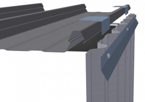
Figure KK CY Screw Fixing Detail 007
Notes:
1. Provide screw at every rib.
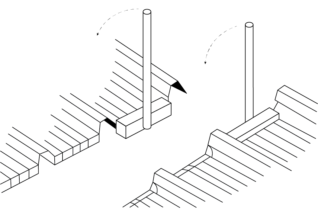

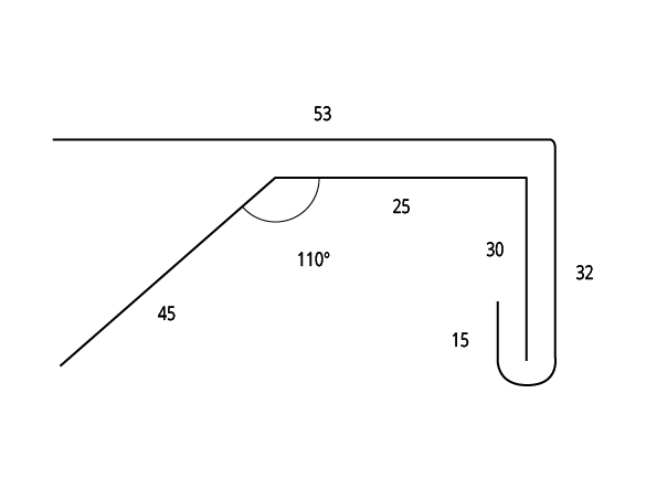
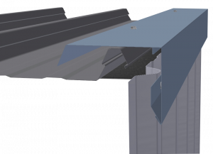
Typical Barge Flashing Detail

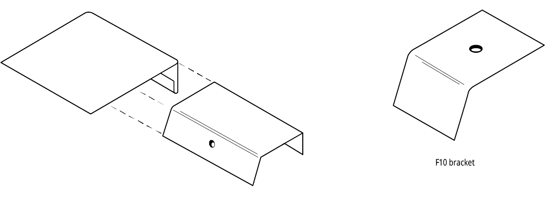
Sliding Bracket Assembly

Typical Flashing (i.e Barge Flashing) fixed to Sliding Bracket Clip

*Notes:
1. Locate sliding bracket away from supports
2. Spacing of sliding bracket as per AS 1562.1
Cyclonic wind regions: 500mm centres (max)
Non cyclonic wind regions: No more than support spacings
3. *Clearance to prevent fastener interferences
4. Barge dimensions and positioning to cladding to comply
with relevant standards, legislation and accepted trade
practice.
Installation Procedure
Step One
Screw fix Sliding Bracket Bases to rib of roof sheeting at nominated spacings.
Step Two
Slide Sliding Bracket Caps over the top of the Sliding Bracket Bases.
Step Three
Install barge flashing side support bracket at nominated spacings
Step Four
Lay barge flashing in place and fix to centre of Sliding Bracket Caps