Rainfall Capacity
For further information, please refer to sections “Rainfall Intensity” and “Water Carrying Capacity and Rainwater Run-Off”.
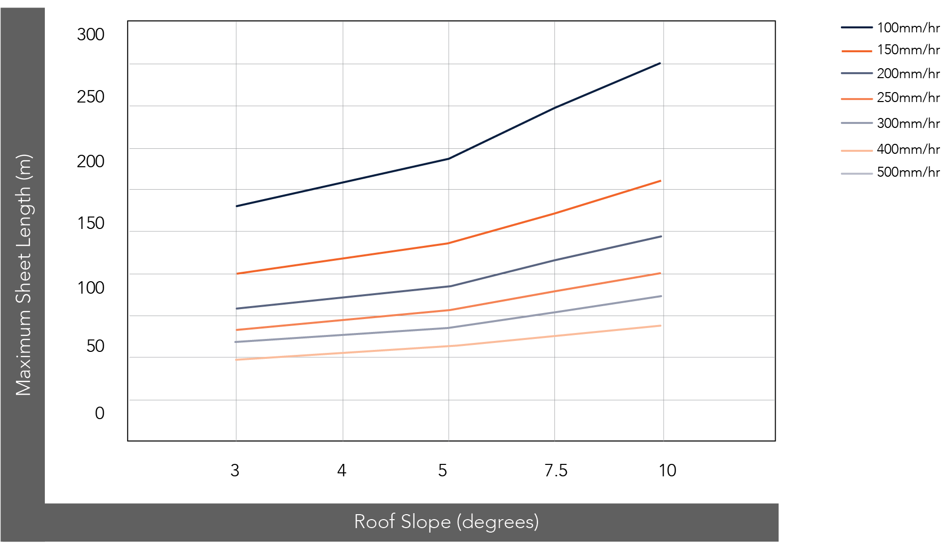
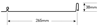
Figure PR RC CY (265) 001
Installation Layout
Plywood

Figure PR ID CY 001
Steel Batten
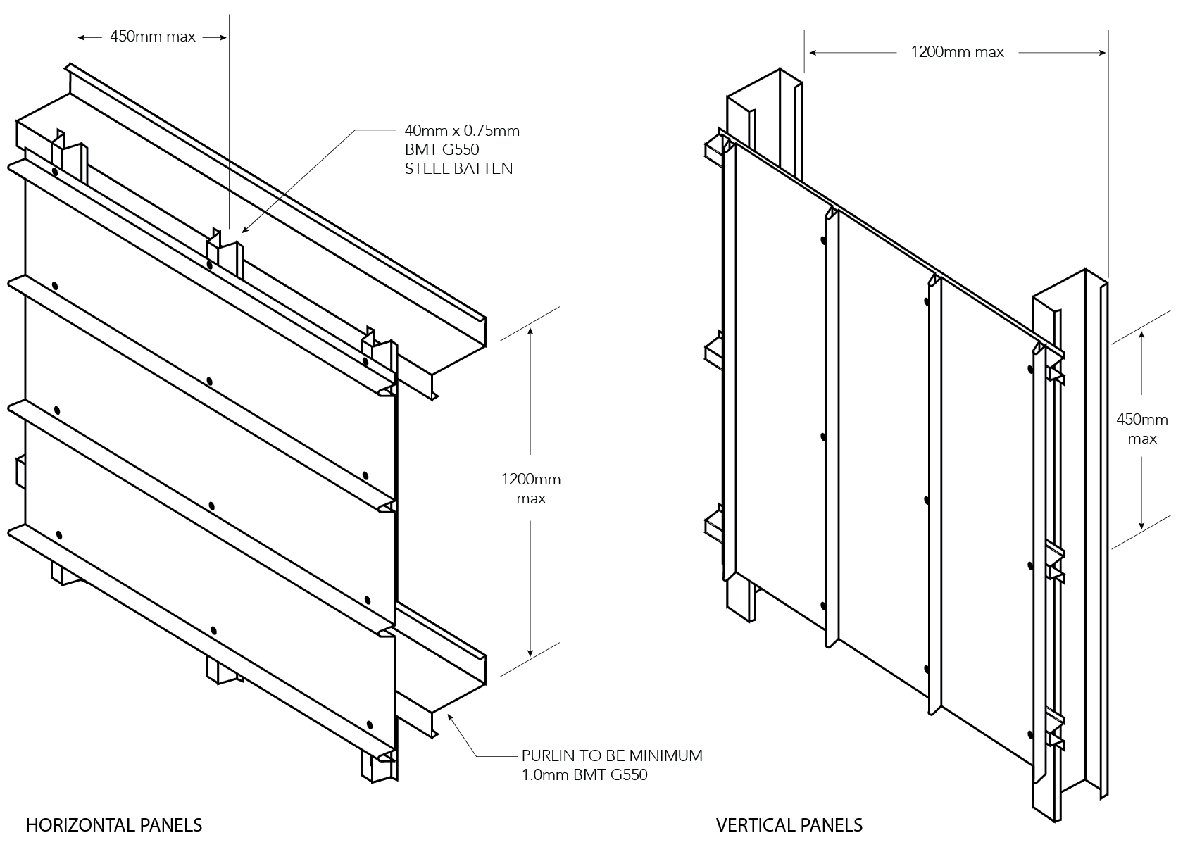
Figure PR ID CY 002
Rib End Stitching Detail for Cyclonic Areas
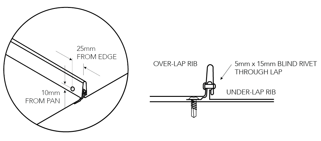
Figure PR ID CY 003
Cyclonic Fixing to KF40® Substrate
Vertical Panels
Where resistance to wind-borne debris is required as per AS/NZS 1170.2: 2011, KF40® backing is required as per the following details:
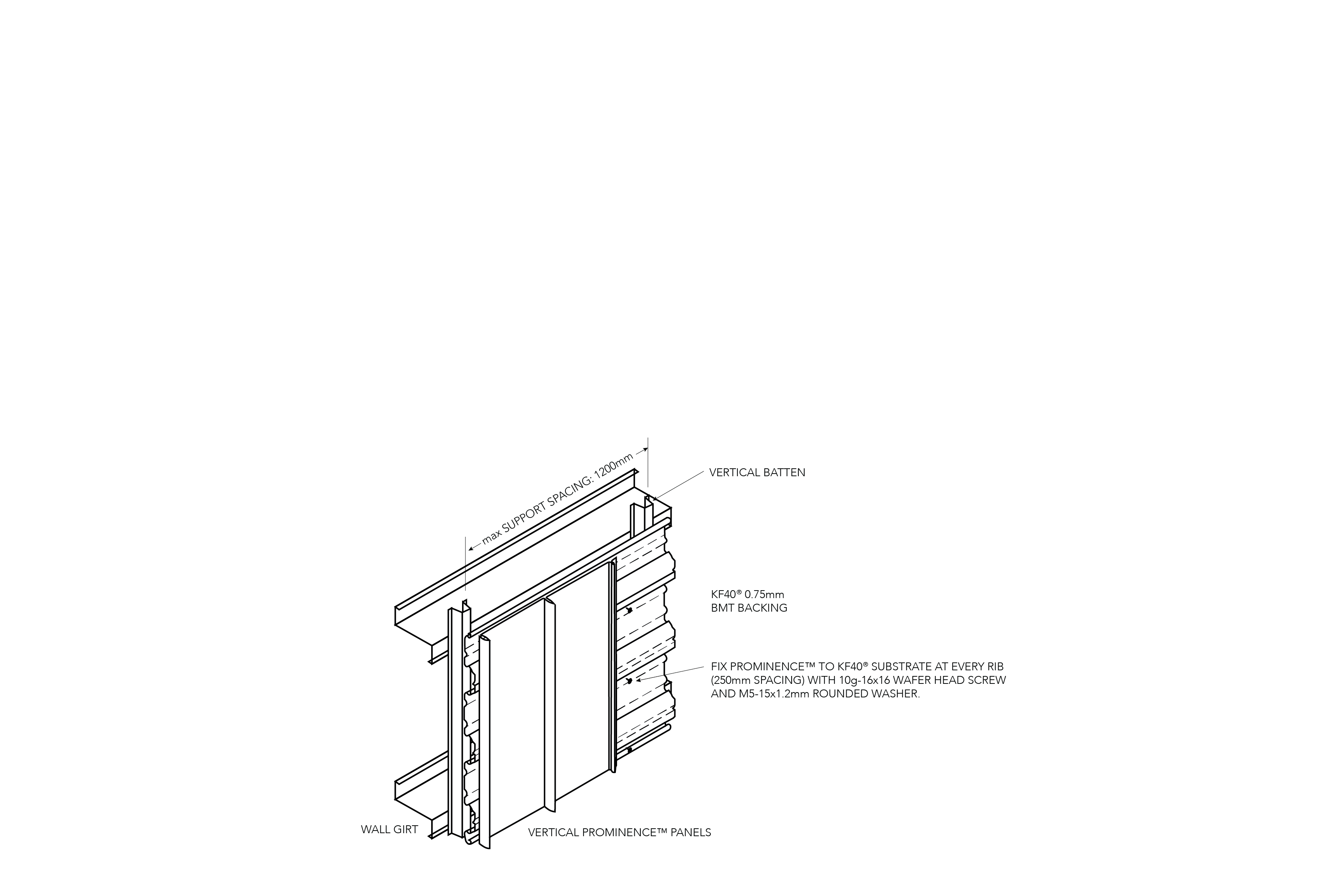
Figure PR ID CY 004
Horizontal Panels
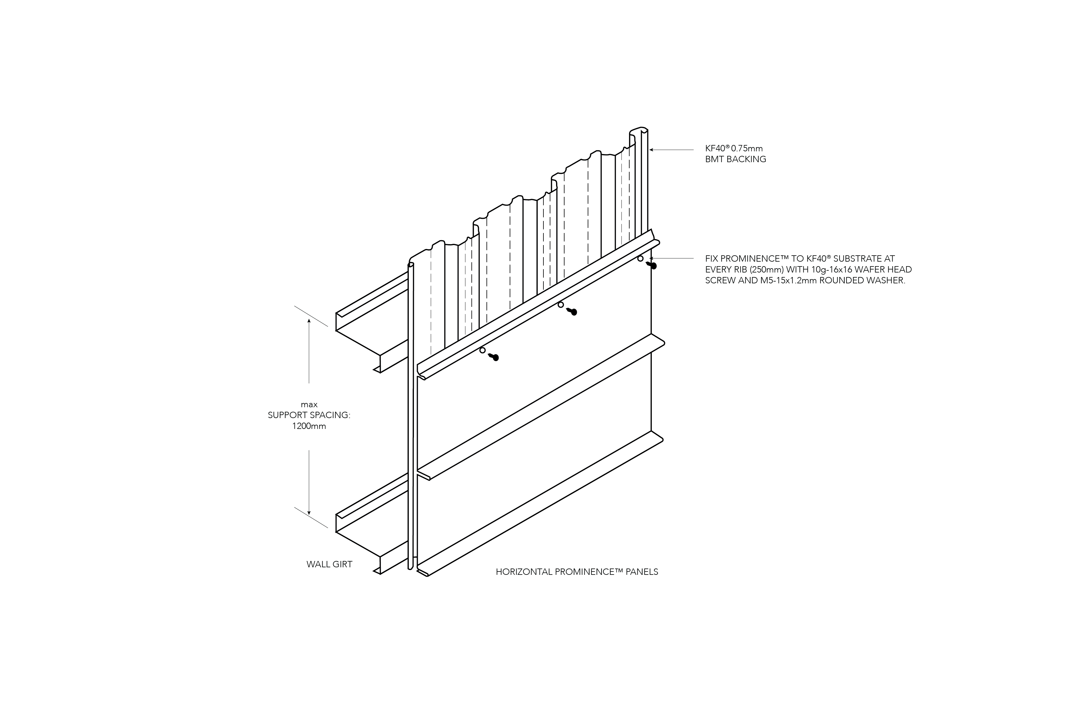
Figure PR ID CY 005
Installation Details
Window Details - Horizontal Panels
HORIZONTAL PANEL AROUND OPENING
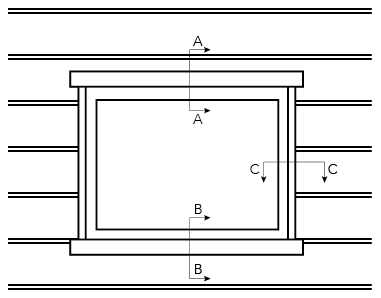
Figure PR ID CY 006
Horizontal Panel Sections
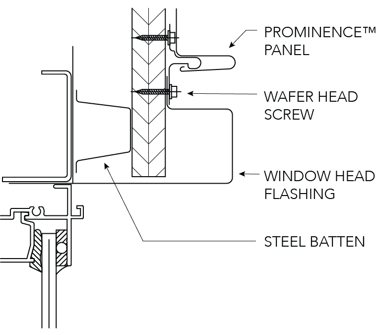
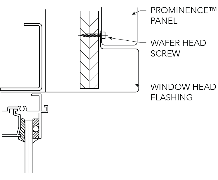
SECTION A-A HEAD
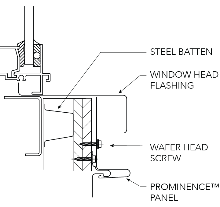
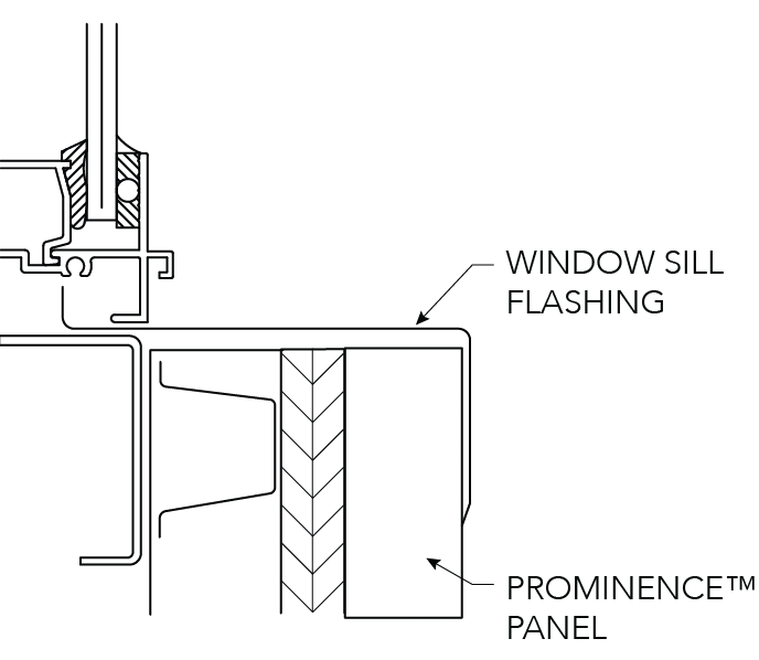
SECTION B-B SILL
SECTION C-C JAMB
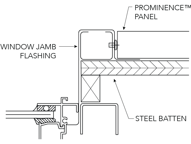
Figure PR ID CY 007
Note:
Head and sill flashings to be turned up and down behind jamb flashing
Window Details - Vertical Panels
VERTICAL PANEL AROUND OPENING
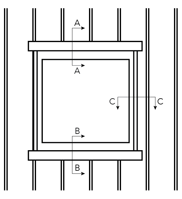
Figure PR ID CY 008
Vertical Panel Sections
SECTION A-A HEAD
SECTION B-B SILL
SECTION C-C JAMB
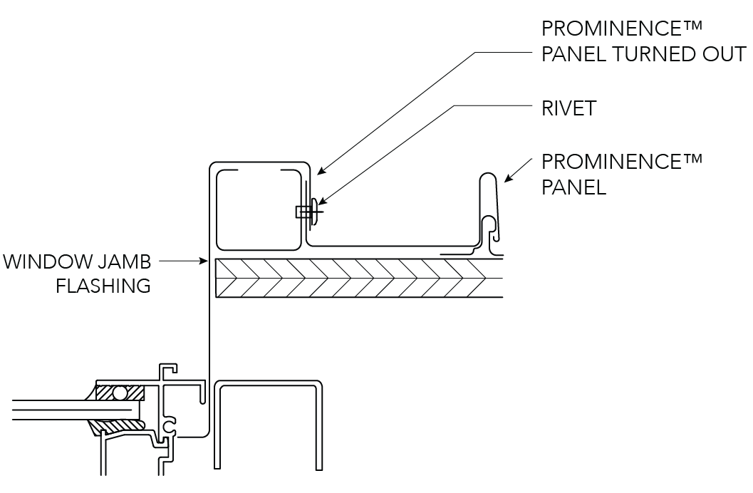
Figure PR ID NC 009
Note:
Head and sill flashings to be turned up and down behind jamb flashing
Corner Construction - Horizontal Panels
INTERNAL CORNER
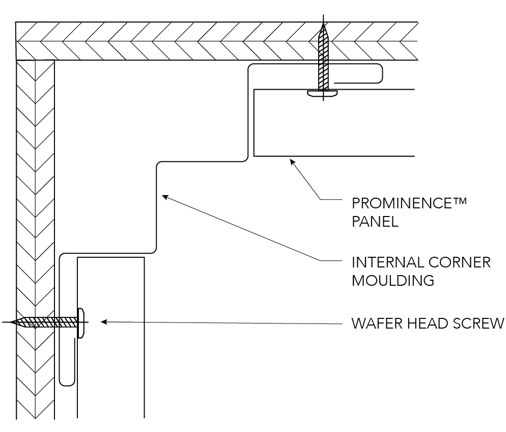
EXTERNAL CORNER
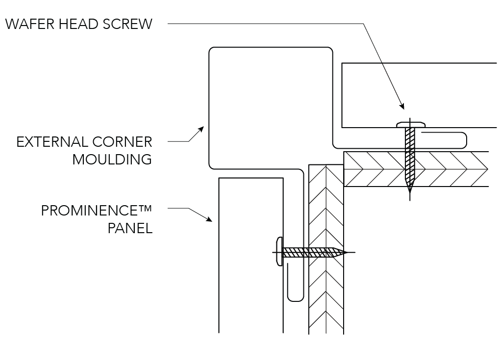
Figure PR ID CY 010
Corner Construction - Vertical Panels
INTERNAL CORNER
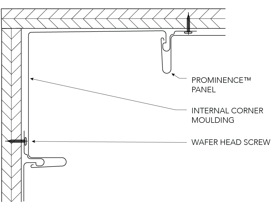
EXTERNAL CORNER
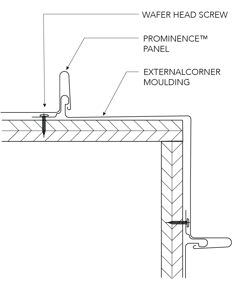
Figure PR ID CY 011
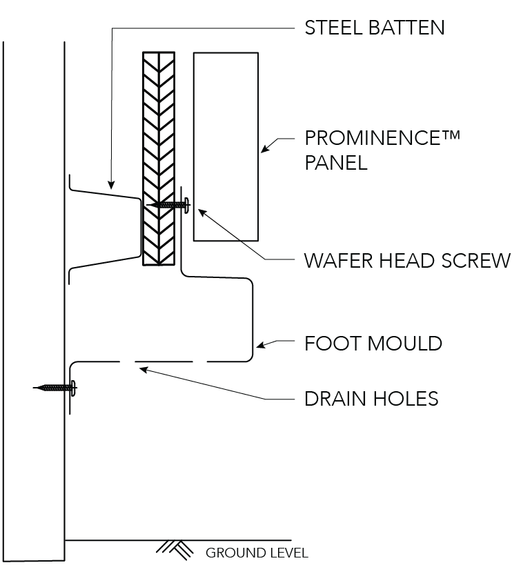
Foot Mould and Bottom of Facade
FOOT MOULD
HORIZONTAL PANELS
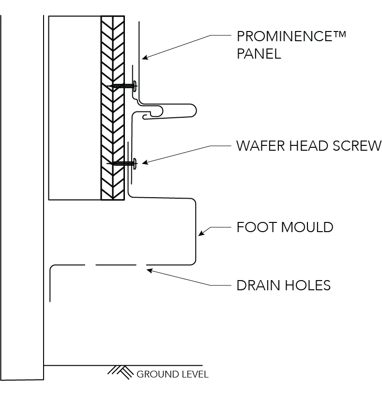
FOOT MOULD
VERTICAL PANELS
BOTTOM OF FACADE
HORIZONTAL PANELS
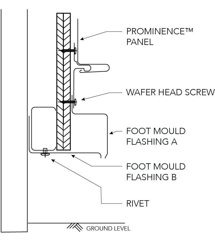
Figure PR ID CY 012
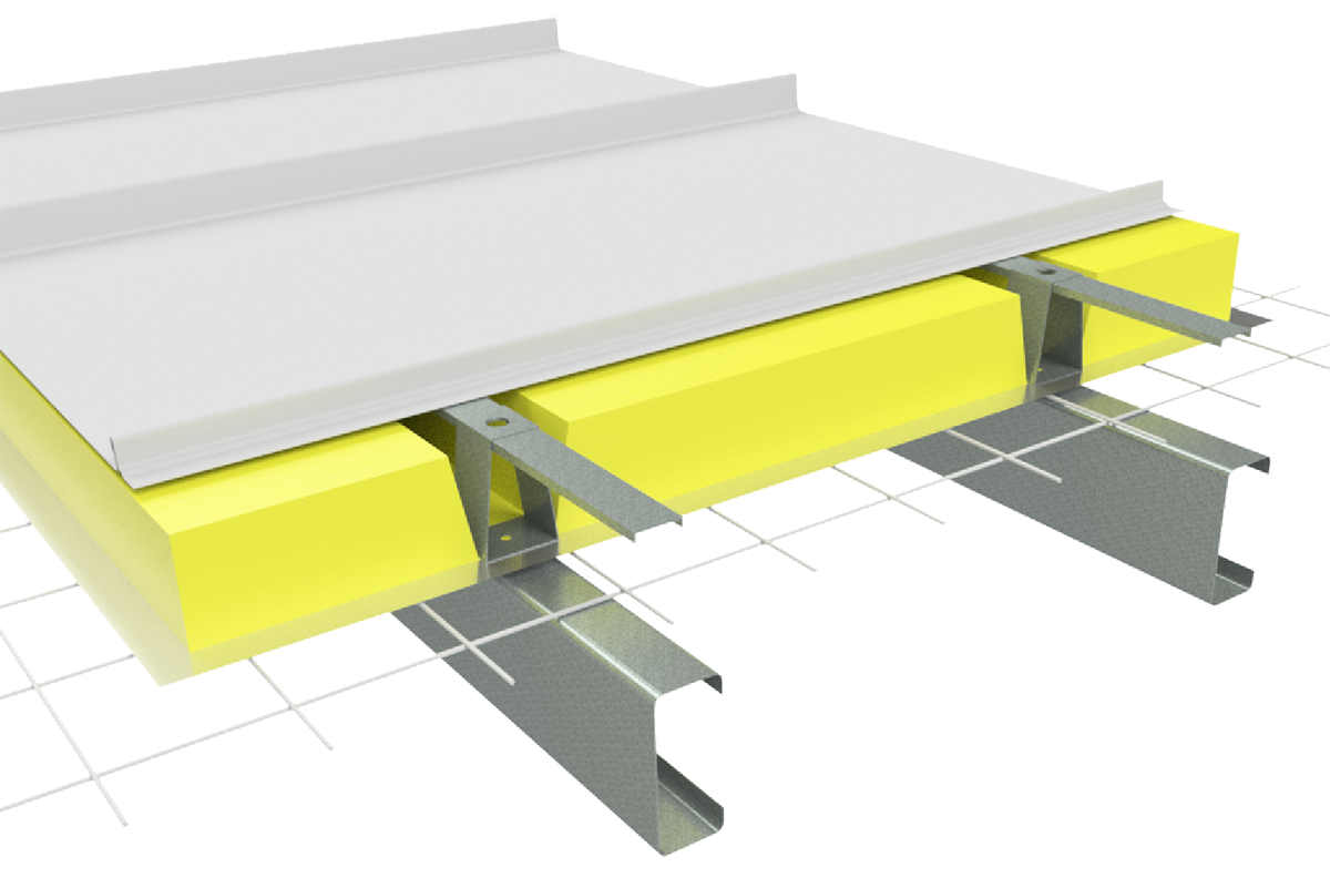
PR INS CY 001
Note:
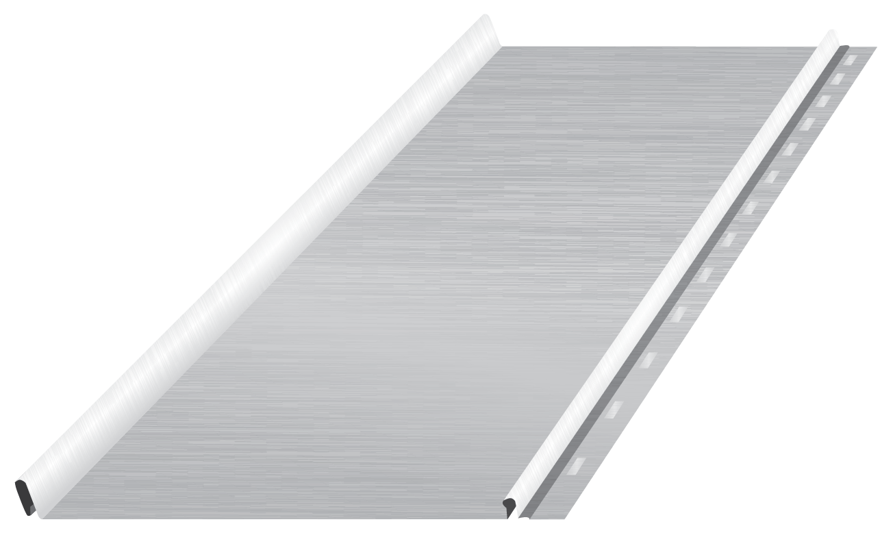
Image displayed using Shadowline profile