
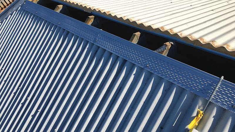
How the system works
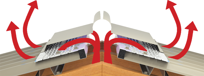
Figure 1.1
This deceptively simple passive system allows fresh outside air to be taken into the roof space either through soffit/eave vents or in through the system itself. This cooler air rises from these intake points and mixes within the ceiling or building space to create a natural flow of air that leaves the hot air escaping through the top of the ridge/skillion.
Simultaneously, external breezes provide a positive airflow which crosses over the ridge of the house creating negative pressure which pulls air out from the ridge vent. Effectively, two thermal effects create a continuous flow of air, allowing cool air into the roof/building space whilst extracting hot air.
Airflow Calculations
| Single storey house | Wind Pressure Pa | Wind speed | External air temp differential to attic space air temp (degrees Celsius | 300mm whirlybird | lm VENT-A-ROOF® louvre skillion ridge (with 45-50mm throat dimension) | lm VENT-A-ROOF® louvre Gable/ Hip Ridge (2m of louvre) (with 45-50mm throat dimension) | lm VENT-A-ROOF® louvre skillion ridge = 1x300mm whirlybird | lm VENT-A-ROOF® louvre gable/hip ridge (2m of louvre) |
||||||
| km/h | Knots | Airflow (m3/s) | Heat Extraction (kW | Airflow (m3/s) | Heat Extraction (kW | Airflow (m3/s) | Heat Extraction (kW | Airflow (m3/s) | Heat Extraction (kW | Airflow (m3/s) | Heat Extraction (kW |
|||
| 0 | 0 | 0 | 6 | 0.019 | 0.137 | 0.006 | 0.046 | 0.013 | 0.091 | 3 | 3 | 1.5 | 1.5 | |
| 12 | 0.020 | 0.288 | 0.007 | 0.096 | 0.013 | 0.092 | 3 | 3 | 1.5 | 1.5 | ||||
| 18 | 0.021 | 0.454 | 0.007 | 0.151 | 0.014 | 0.302 | 3 | 3 | 1.5 | 1.5 | ||||
| 40 | 0.022 | 1.056 | 0.007 | 0.352 | 0.015 | 0.704 | 3 | 3 | 1.5 | 1.5 | ||||
| 2.0 | 6 | 3.2 | 6 | 0.029 | 0.206 | 0.01 | 0.069 | 0.019 | 0.138 | 3 | 3 | 1.5 | 1.5 | |
| 12 | 0.030 | 0.429 | 0.01 | 0.143 | 0.020 | 0.286 | 3 | 3 | 1.5 | 1.5 | ||||
| 18 | 0.031 | 0.677 | 0.01 | 0.226 | 0.021 | 0.451 | 3 | 3 | 1.5 | 1.5 | ||||
| 3.6 | 8 | 4.3 | 6 | 0.034 | 0.247 | 0.011 | 0.082 | 0.023 | 0.165 | 3 | 3 | 1.5 | 1.5 | |
| 12 | 0.035 | 0.5 | 0.012 | 0.167 | 0.023 | 0.333 | 3 | 3 | 1.5 | 1.5 | ||||
| 18 | 0.036 | 0.787 | 0.012 | 0.262 | 0.024 | 0.524 | 3 | 3 | 1.5 | 1.5 | ||||
| 8.0 | 12 | 6.5 | 6 | 0.051 | 0.37 | 0.017 | 0.123 | 0.034 | 0.246 | 3 | 3 | 1.5 | 1.5 | |
| 12 | 0.052 | 0.753 | 0.017 | 0.251 | 0.035 | 0.502 | 3 | 3 | 1.5 | 1.5 | ||||
| 18 | 0.053 | 1.137 | 0.018 | 0.379 | 0.035 | 0.758 | 3 | 3 | 1.5 | 1.5 | ||||
| 12.5 | 15 | 8.1 | 6 | 0.060 | 0.432 | 0.02 | 0.144 | 0.040 | 0.288 | 3 | 3 | 1.5 | 1.5 | |
| 12 | 0.060 | 0.871 | 0.02 | 0.29 | 0.040 | 0.58 | 3 | 3 | 1.5 | 1.5 | ||||
| 18 | 0.061 | 1.324 | 0.02 | 0.441 | 0.041 | 0.882 | 3 | 3 | 1.5 | 1.5 | ||||
| 14.2 | 16 | 8.6 | 6 | 0.063 | 0.456 | 0.021 | 0.152 | 0.042 | 0.304 | 3 | 3 | 1.5 | 1.5 | |
| 12 | 0.065 | 0.935 | 0.022 | 0.312 | 0.043 | 0.623 | 3 | 3 | 1.5 | 1.5 | ||||
• Increasing wind speeds will cool a sunlit roof hence reductions in attic v ambient temperatures for higher wind speeds.
• Bolded text represents default Australian design pressure of 12.5 Pa.

Step 1 - Roof Sheeting Installation
Install Fielders® S-Rib™, Fielders® TL-5™ or Fielders® KingKlip®700 sheeting in accordance with installation details available on this website.
Critical dimensions for roof ridge batten position and ridge throat dimensions are shown at Figure 3.1.1.
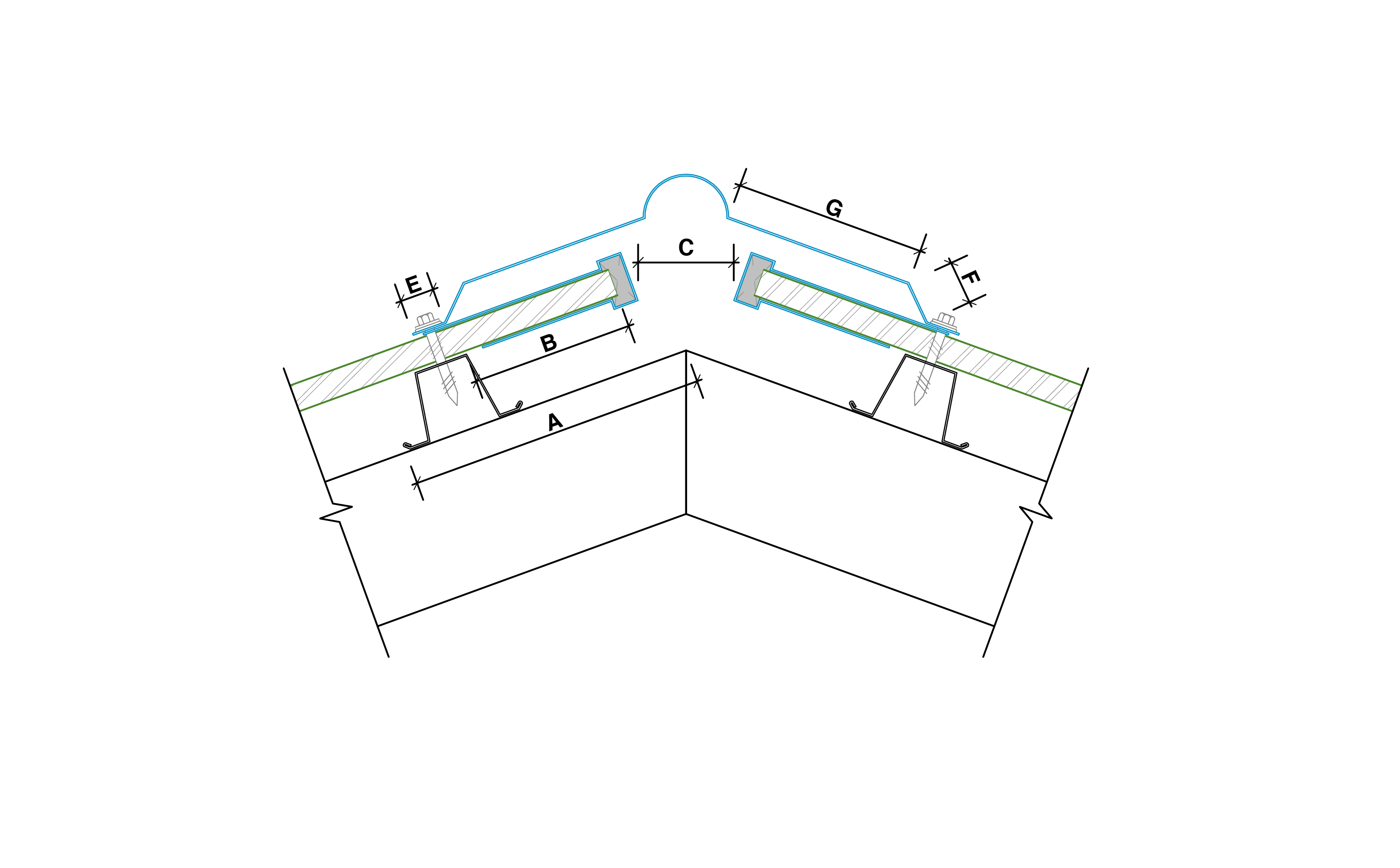
Figure 3.1.1
Fielders® Roll Top Ridge
| Dimensions (mm) | ||||||||
| Batten | Sheet | Throat | Ridge | |||||
| Apex ridge to toe of batten | Sheet overhang top of batten | Sheet to sheet | Ridge legs | |||||
| 15˚ | 22.5˚ | 25˚ | Toe | Step/Raise | Pan | |||
| State | A | B | C | E | F | G | ||
| NSW | 175 | 165 | 160 | 95 | 60-55 | 17.5 | 25 | 106 |
| VIC | 175 | 170 | 165 | 90 | 55-50 | 17.5 | 25 | 102 |
| TAS | 175 | 170 | 165 | 90 | 55-50 | 17.5 | 25 | 102 |
| SA | 165 | 155 | 150 | 91 | 30-17 | 12 | 22 | 91 |
| WA | 170 | 160 | 155 | 95 | 50-45 | 20 | 25 | 99 |
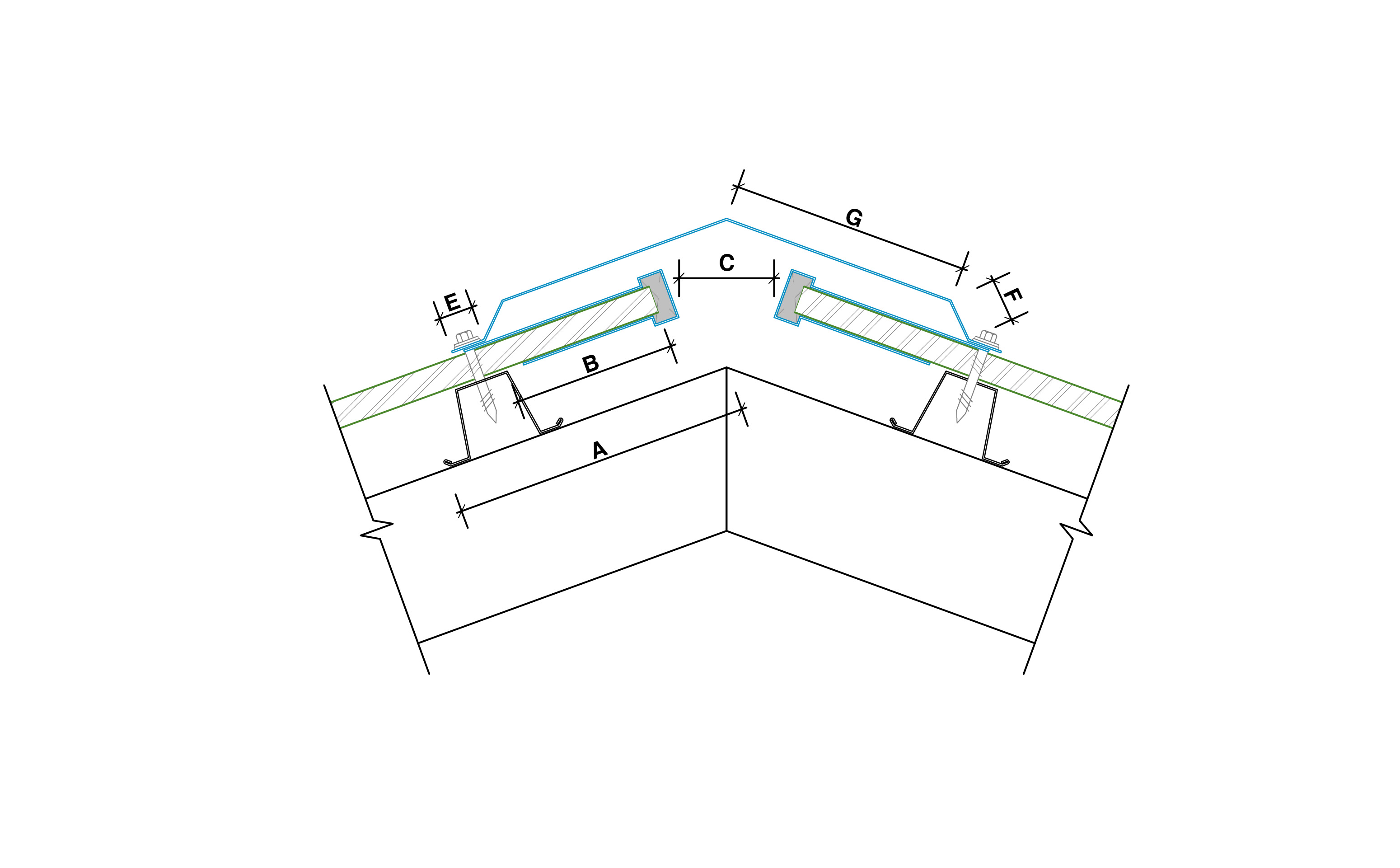
Figure 3.1.2
Fielders® Folded Ridge
| Dimensions (mm) | |||||||||
| Batten | Sheet | Throat | Ridge | ||||||
| Apex ridge to toe of batten | Sheet overhang top of batten | Sheet to sheet | Ridge legs | Feed width |
|||||
| 15˚ | 22.5˚ | 25˚ | Toe | Step/Raise | Pan | ||||
| Region | A | B | C | E | F | G | (mm) | ||
| Non cyclonic | 180 | 175 | 170 | 95 | 55-65 | 22 | 25 | 150 | 400 |
| Cyclonic | 205 | 200 | 195 | 95 | 100-110 | 22 | 25 | 175 | 45 |

Figure 3.1.3
Fielders® Folded Ridge (Commercial applications)
| Dimensions (mm) | |||||||||||
| Batten | Sheet | Throat | Ridge | ||||||||
| Apex ridge to purlin edge | Sheet overhang top of Purlin | Sheet to sheet | Ridge barge legs | Feed width |
|||||||
| 1˚ | 5˚ | 15˚ | 1˚ | 5˚ | 15˚ | Toe | Step/Raise | Pan | |||
| Application | A | B | C | E | F | G | (mm) | ||||
| Commercial/Industrial | 173 | 95 | 110 | 140-180 | 22 | 25 | 200 | 500 | |||
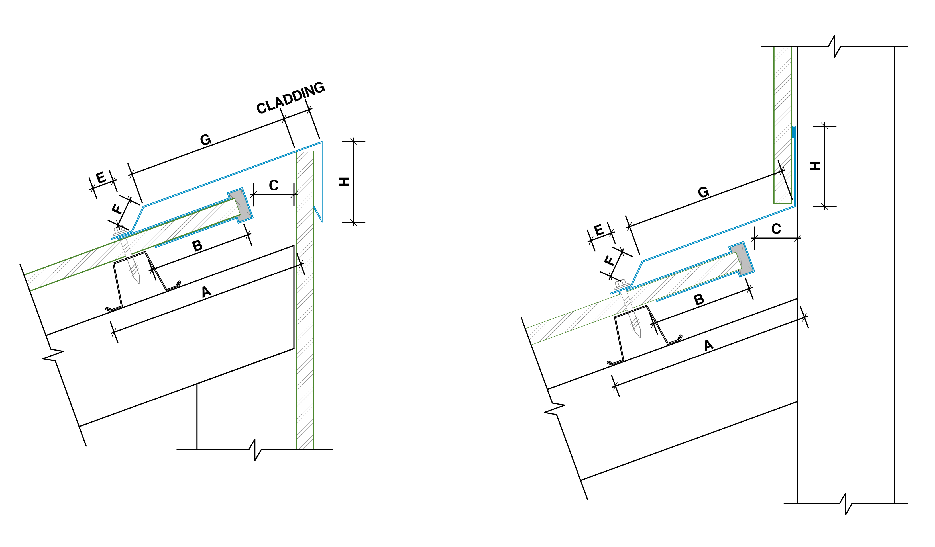
Figure 3.1.4
Skillion Roof Ridge/Apron
| Dimensions (mm) | |||||||||
| Batten | Sheet | Throat | Ridge Barge/Apron | ||||||
| Apex ridge to toe of batten | Sheet overhang top of batten | Sheet to sheet | Ridge barge legs | ||||||
| 15˚ | 22.5˚ | 25˚ | Toe | Step/Raise | Pan | Wall side | |||
| Region | A | B | C | E | F | G | H | ||
| Non cyclonic | 190 | 185 | 180 | 95 | 40-35 | 25 | 25 | 150 | 75 |
| Cyclonic | 240 | 235 | 230 | 95 | 90-85 | 25 | 25 | 200 | 75 |
It is important that a consistent line is maintained at the ridge line of sheeting as per the dimensions noted in Figure 3.1.1-3.1.4 and the above tables as appropriate. Do not screw fix the ridge line of roof sheets. Sheet pans should not be turned up.
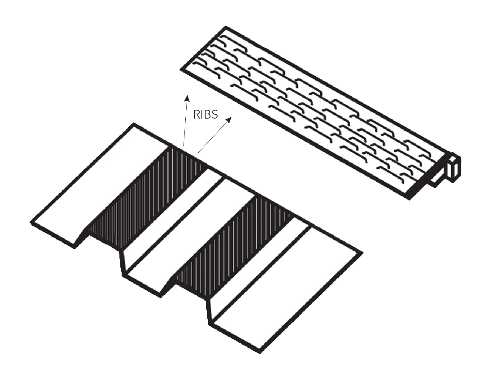
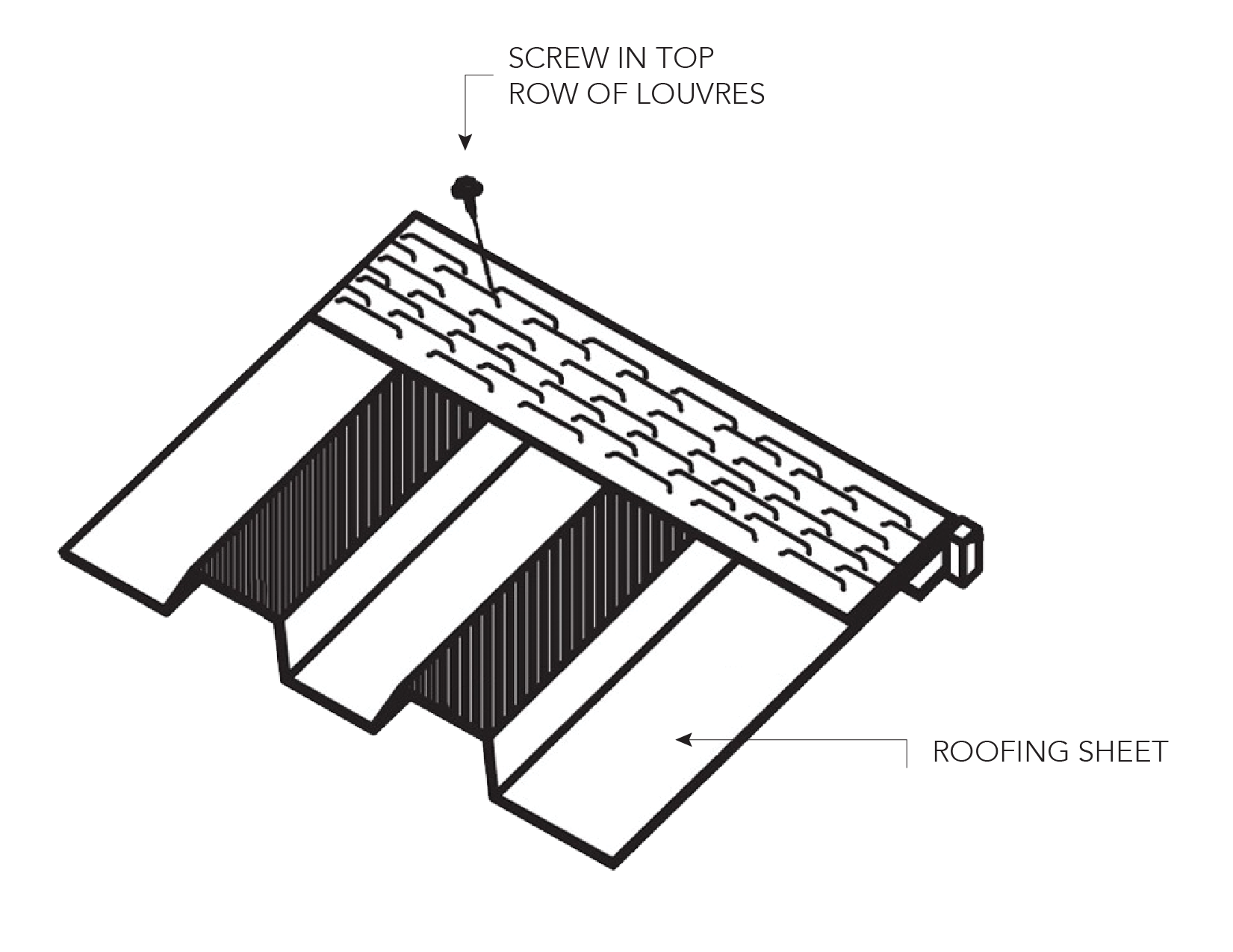
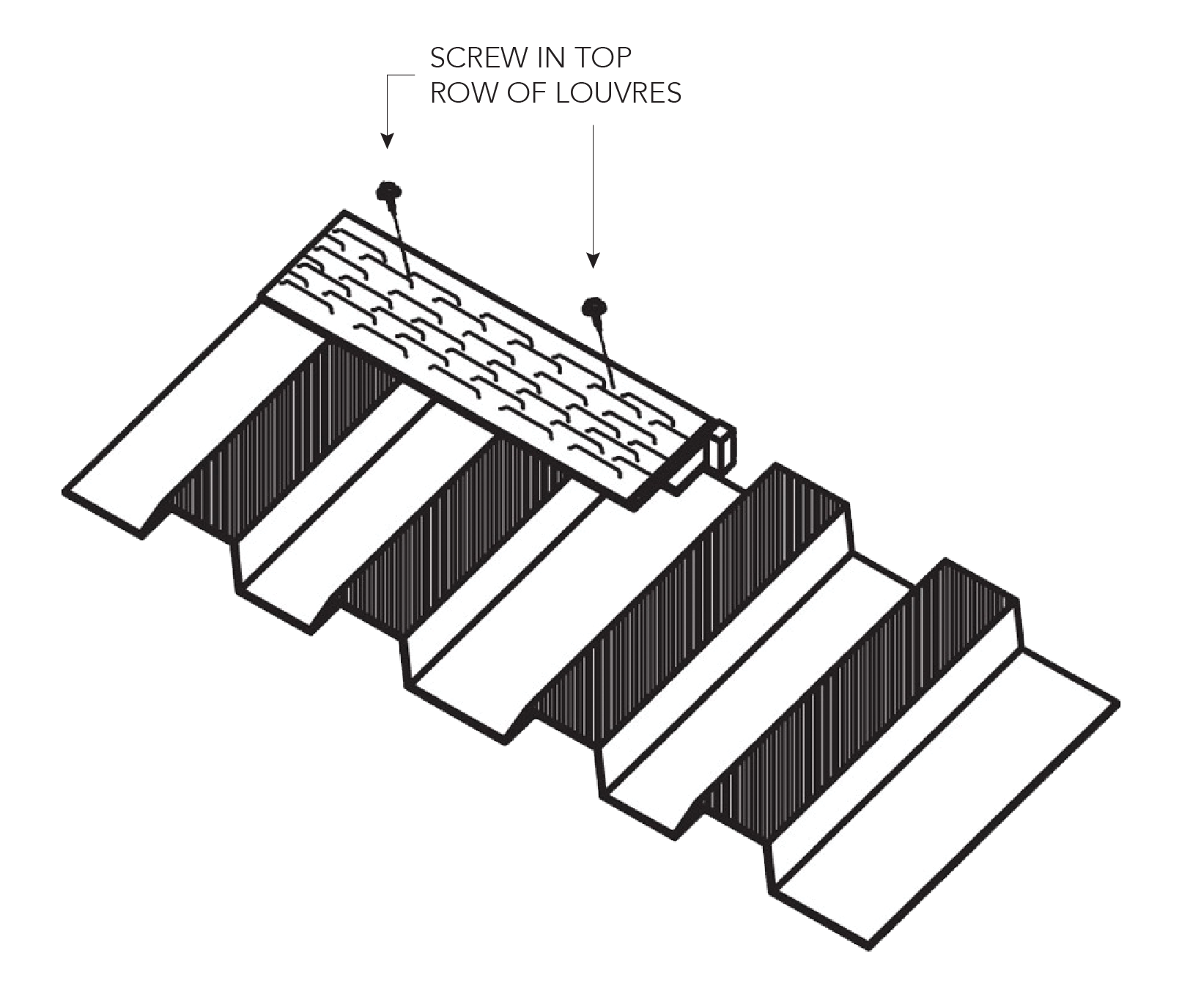
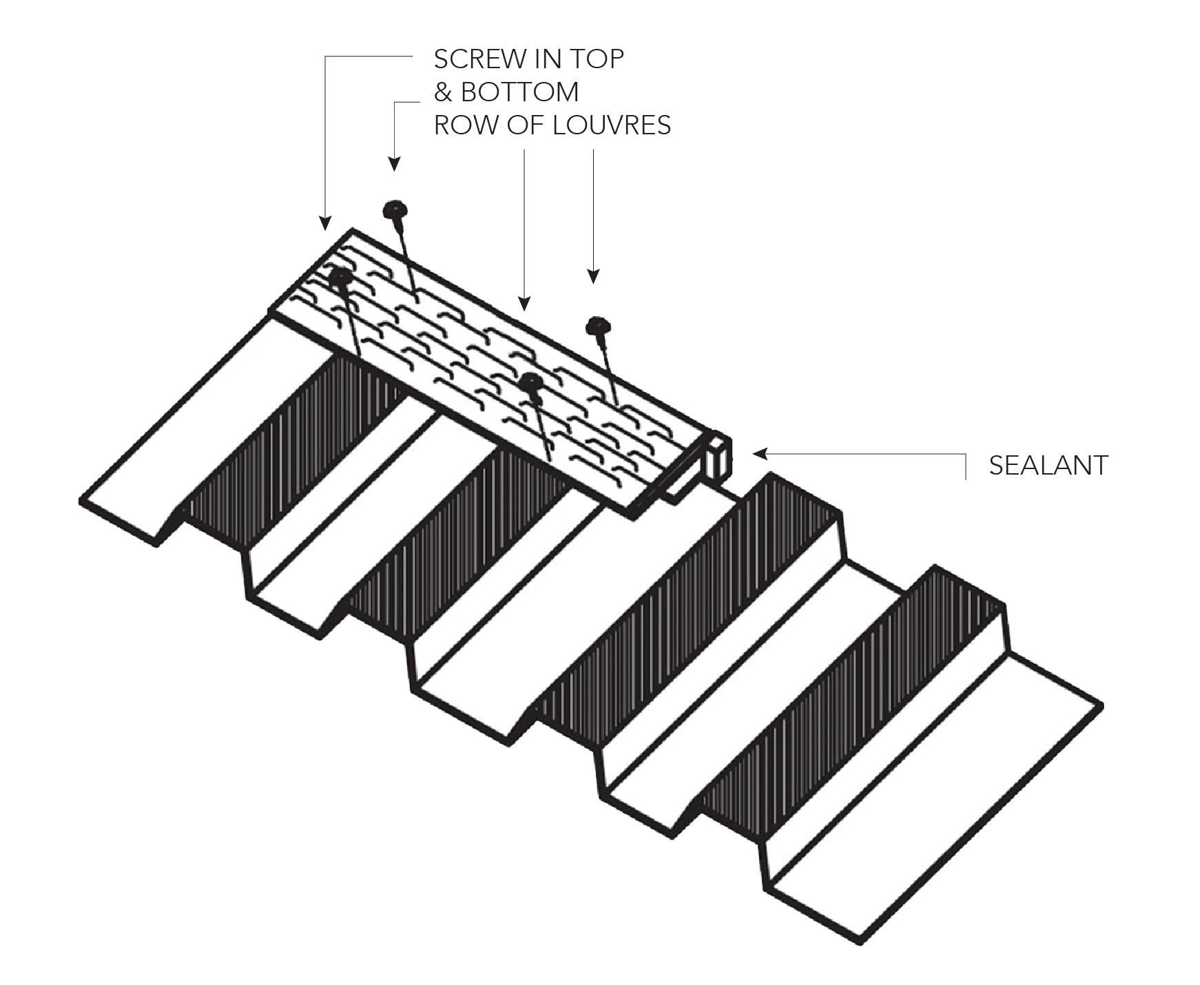
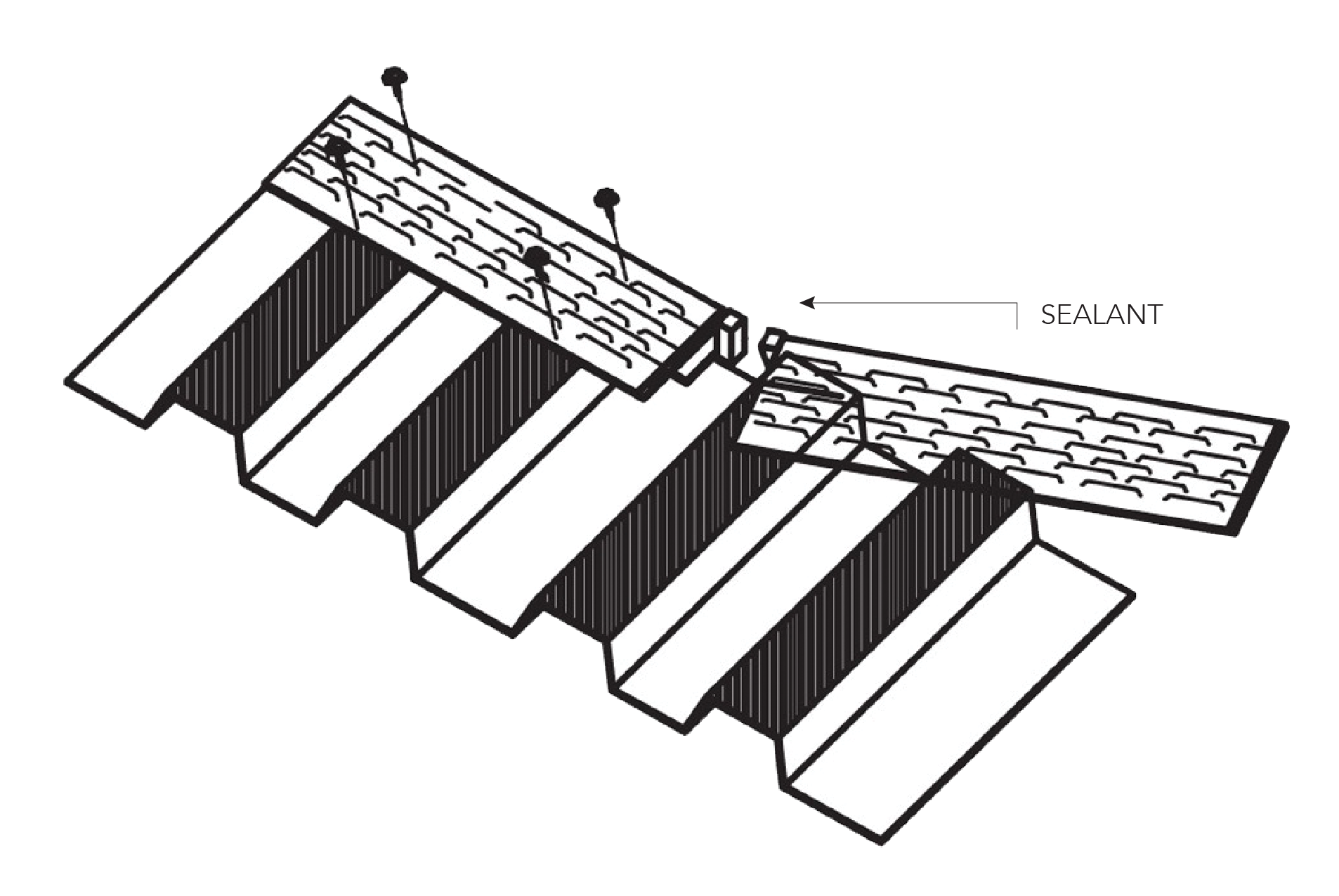


Figure 3.6.1
Screw pattern
Cyclonic and Non Cyclonic
Louvre fixing screw pattern - Cyclonic and Non Cyclonic applications
| Fielders® | |||||
| Sheet Type | S-Rib™ | TL-5™ | KingKlip®700 | Screw | |
| Recommended spacing of VENT-A-ROOF® fixing screws | 1st and last sheet rib | 10 - 16 x 16mm Teks® |
|||
| then every 4th rib | then every 2nd rib | then every rib | |||
| Distance from front/bottom edge of VENT-A-ROOF® louvre | 60mm | ||||
| Distance from top edge of VENT-A-ROOF® louvre | 25mm | ||||
| Fixing spacing at VENT-A-ROOF® joints | Both sides of join | ||||
| Spacing of ridge cap fixing screws | Every 2nd rib | Every rib | Every rib | As per Fielders® published data for roof sheeting |
|
| for cyclonic applications cyclonic zips should be used for ridge cap fixing screws |
|||||

Appendices
FORM 15 – BAL-12.5 – 40
![]()
FORM 15 Australian wind regions A 1-7, B, C & D
![]()
JCE A150 - Letter of advice - VENT-A-ROOF® product
![]()
Performance test summary TAS-100A on EZ VENT-N-CLOSURE for VENT-A-ROOF®
![]()
Performance test report ASTM E283 leakage test on metal roof vent for VENT-A-ROOF®
![]()