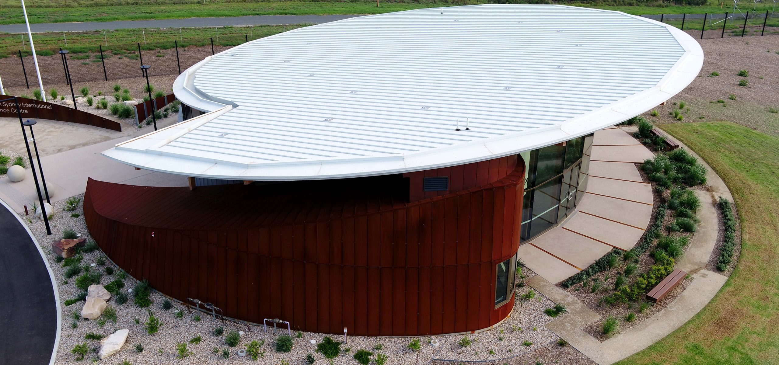
About Cadence®
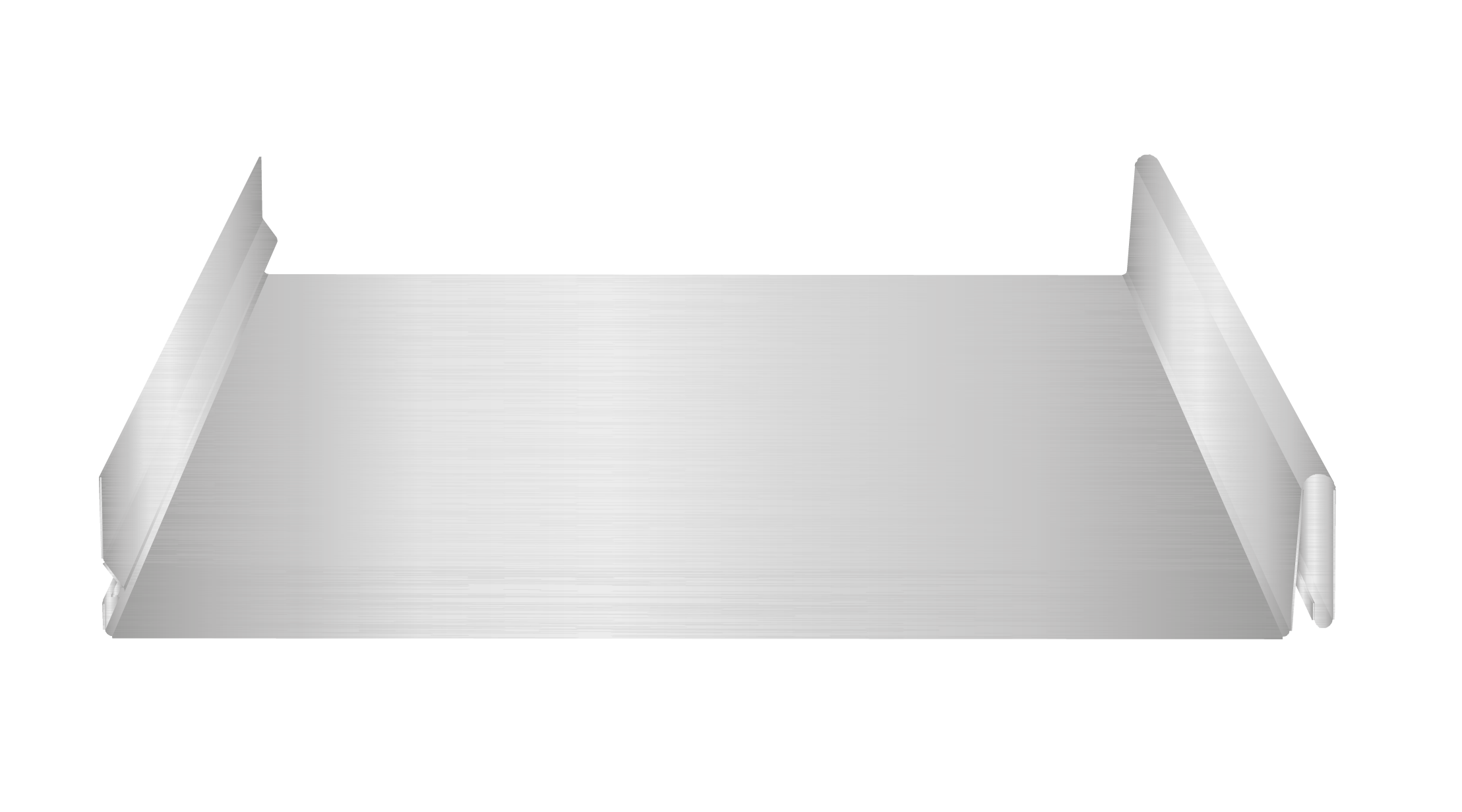
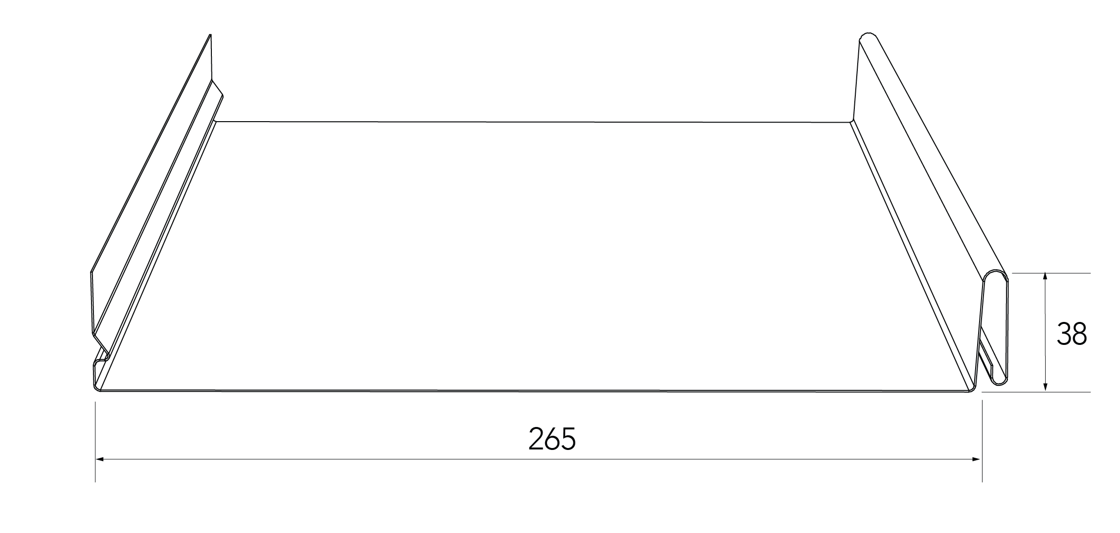
With its elegant flat pans and ease of installation, Fielders Cadence® offers all of the aesthetic benefits of Fielders Prominence™ with additional structural capacities due to the clever concealed fix bracket fixings. These brackets enhance the profile's ability to deal with thermal expansion and contraction. Fielders Cadence® is available in a 265mm and a 465mm wide panel.
As with all the profiles in the Fielders Finesse® range, Fielders Cadence® is available in any COLORBOND® steel colour you choose and looks particularly striking in a Metallic COLORBOND® steel. Cadence® is also available in 0.75mm steel and 0.9mm aluminium (subject to minimum order quantities). Contact your local Fielders representative for availability and further information.
Fielders Cadence® is suitable for installation on traditional supporting substrates such as plywood and fibre cement panels, and now with comprehensive testing, can be offered on cost effective steel battens.
Material Specifications
| Property | 265mm Pan Width | Notes | |||
| Base Metal Thickness (mm) | 0.55 | 0.70 | 0.75 | BMT | |
| Total Coated Thickness (mm) | 0.60* | 0.75* | 0.80* | TCT | |
| Mass / Unit Length | ZINCALUME® steel | 1.83 | 2.25 | 2.41 | kg/m |
| COLORBOND® steel | 1.96* | 2.29 | 2.44* | ||
| Mass / Unit Area | ZINCALUME® steel | 6.91 | 8.50 | 9.09 | kg/m2 |
| COLORBOND® steel | 7.02* | 8.65* | 9.21* | ||
| Coverage | 265 | mm | |||
| Minimum Yield Strength | G300 | 300 MPA | |||
| Coating Class | AM100 - COLORBOND® steel AM100 - COLORBOND® Metallic steel AM125 - ZINCALUME® steel AM150 - COLORBOND® Ultra steel | Minimum Coating g/m2 of Zinc - Aluminium |
|||
| Tolerance | Sheet length ±3mm Cover width ±2mm | ||||
| Thermal Expansion | 2.9mm average per 5.0 metre @ 50˚C change | ||||
Notes:
- The COLORBOND® steel and ZINCALUME® steel material is in accordance to AS 1397, AS 1365 and AS 2728.
- Installation of the cladding should also be in accordance to AS 1562.1 and HB 39.
- *is based on Standard COLORBOND®; steel single-sided material. For other painted steel options please contact a Fielders® representative.
Rainfall Capacity
For further information, please refer to sections “Rainfall Intensity” and “Water Carrying Capacity and Rainwater Run-Off”.
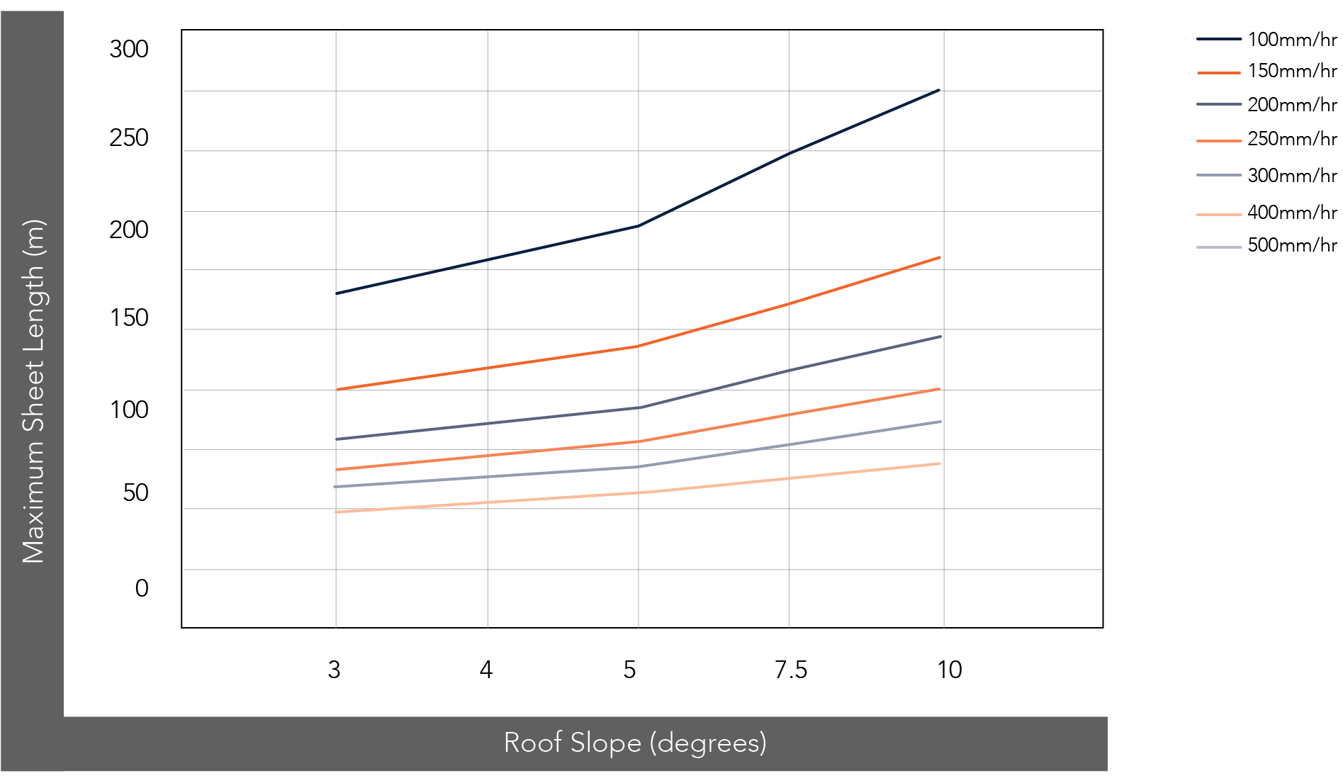
Figure CD C Rainfall
Maximum Roof Length (m) 265 Cyclonic
| Roof Slope (degrees) | Rainfall Capacity (mm/hr) | ||||||
| 100 | 150 | 200 | 250 | 300 | 400 | 500 | |
| 3 | 160 | 107 | 80 | 64 | 53 | 40 | 32 |
| 4 | 180 | 120 | 90 | 72 | 60 | 45 | 36 |
| 5 | 199 | 133 | 100 | 80 | 66 | 50 | 40 |
| 7.5 | 238 | 158 | 199 | 95 | 79 | 59 | 48 |
| 10 | 273 | 182 | 137 | 109 | 91 | 68 | 55 |
Note:
- Minimum recommended slope is 3°. Sheet lengths greater than 15m are not recommended due to thermal expansion and contraction.
Cyclonic Testing
Fielders® have undertaken cyclonic testing of the Cadence® profile in a 265mm panel width for both roofing and walling applications in accordance with the Low-High Low (LHL) cyclonic testing method in the National Construction Code (NCC) and AS4040.
Design data provided for Prominence™ is based on the following Australian Standards:
- AS1170.2:2011 Structural design actions Part 2: Wind actions
- AS1562.1-1992 (R2016) Design and installation of sheet roof and wall cladding Part 1: Metal
- AS4040.0-1992 Methods of testing sheet roof and wall cladding Part 0: Introduction, list of methods and general requirements
- AS4040.1-1992 Methods of testing sheet roof and wall cladding Method 1: Resistance concentrated loads
- AS4040.2-1992 Methods of testing sheet roof and wall cladding Method 2: Resistance to wind pressures for non-cyclone regions
- AS4040.3-1992 Methods of testing sheet roof and wall cladding Method 3: Resistance to wind pressures for cyclone regions
- AS4055:2012 Wind Loads for Housing
SA HB 39: 2015 Handbook - Installation code for metal roof and wall cladding National Construction Code of Australia.
Cadence® can be supported on one of three supporting structures; plywood, steel battens or Fielders® KingFlor® KF40. The cyclonic wind load capacities are shown in Table CD C WC 001.
Cyclonic Impact Resistance from Wind-Borne Debris
Parts of a building envelope (cladding, doors, windows) may be required to resist windborne debris according to AS/NZS 1170.2: 2011 and Technical Note No. 4, ‘Simulated windborne debris impact testing of building envelope components’, Cyclone Testing Station, James Cook University. These standards specify debris impact loading by timber member of 4kg mass with nominal cross-section of 100mm x 50mm and 8mm diameter spherical steel balls. Cadence® (roofing and walling), cyclonic assemblies have been evaluated to effectively resist cyclonic wind-borne debris for wind region C and D when used in conjunction with plywood or KF40® 0.75mm BMT backing for walling applications. Please refer to the relevant fixing requirements for Cadence®.
Wind Pressure Capacities (Strength)
| Cover Width (mm) | Application | BMT (mm) | Cladding Support Options | ||
| CKD Structural Plywood (Cladding Fixed at 450mm c/c) | 40mm Steel Batten (Cladding fixed at 450mm c/c) | KF40® 0.75mm BMT Cladding fixed at 250mm c/c |
|||
| 265 | Walling | 0.55 | 5.18 kpa | 5.18 kpa | 5.18 kpa |
| 265 | Walling | 0.70 | 5.18 kpa | ||
| 265 | Walling | 0.75 | 5.18 kpa | ||
Notes:
- Support and fastener spacings as detailed in Figures CD C FKF40S 001 and CD C FKF40S 002.
- Minimum support thickness must be 1.50mm BMT.
- 15mm CKD Structural Plywood for walling applications. 19mm CKD Structural Plywood for roofing applications or for Impact resistance.
Cyclonic Fixing to KF40® Substrate
Vertical Panels
Where resistance to wind-borne debris is required as per AS/NZS 1170.2: 2011, KF40® backing is required as per the following details:

Figure CD C FKF40S 001
Horizontal Panels
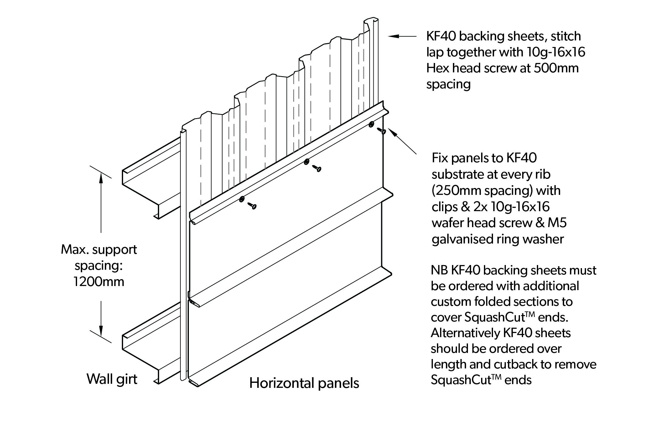
Figure CD C FKF40S 002
Installation
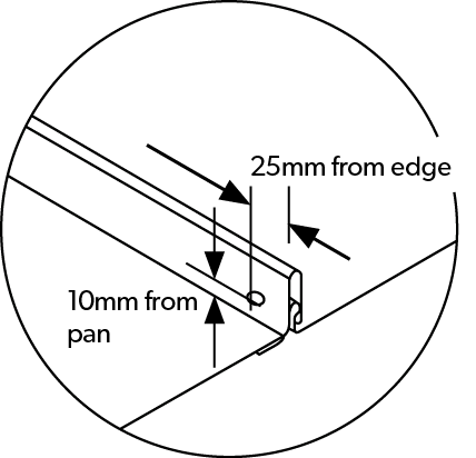
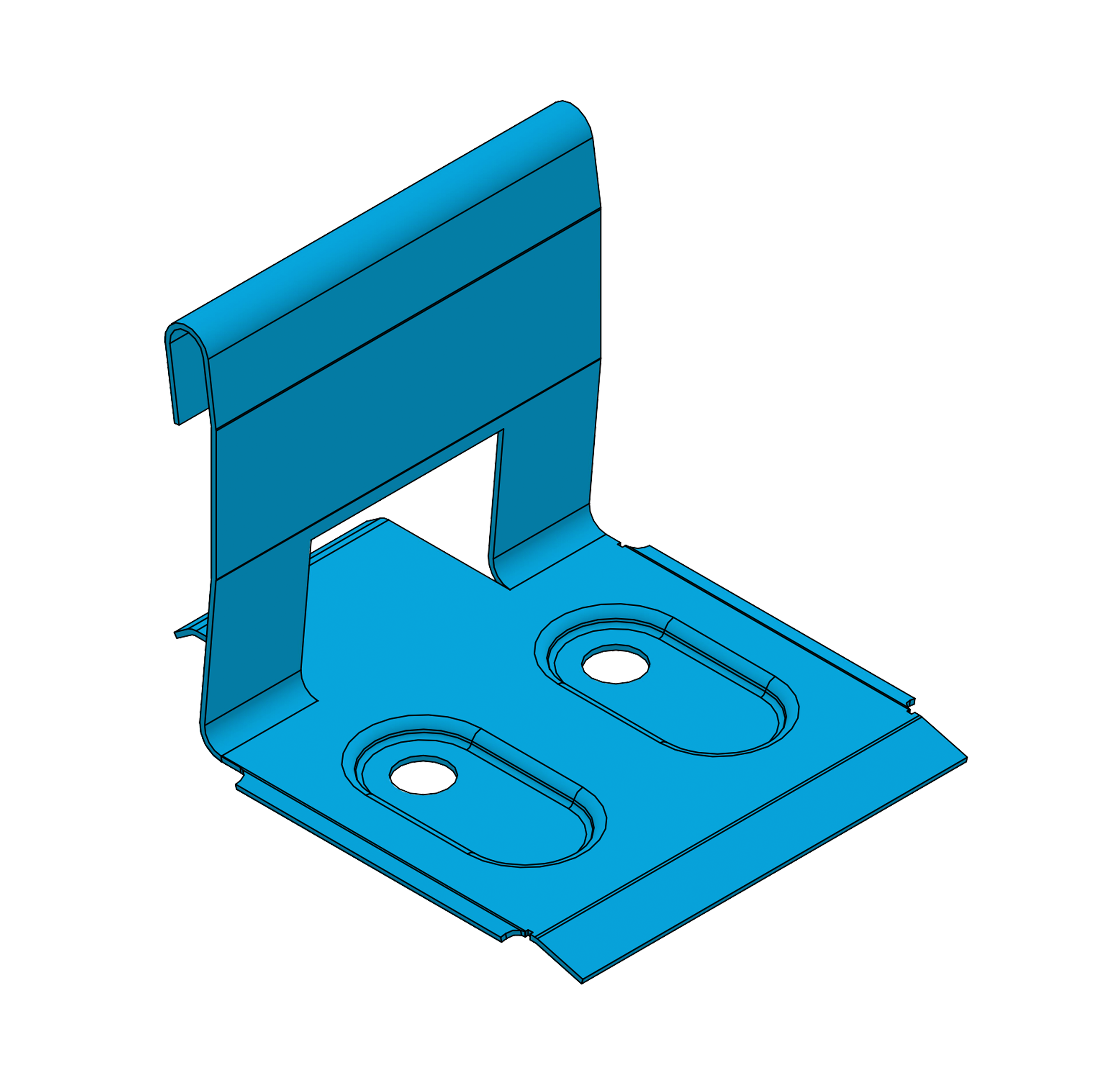
Cadence® is concealed clip-fixed to either plywood or batten supports. This means that clips are screw fastened to the supports and no fastening passes through the sheeting.
Recommended Fasteners
| Supports | Recommended Fastener (without insulation) |
| Steel | 2 x 10g-16x16 Tri-Fixx Flat head metal screw with minimum class 3 coating with clip |
| Plywood | 3 x 10g-12x25 Flat head type 17 screw with minimum class 3 coating with clip |
| Timber | 3 x 10g-12x25 Flat head type 17 screw with minimum class 3 coating with clip |
Notes:
At rib edge the recommended fastener (without insulation) for all supports is 4.8mm Multigrip rivets or equivalent to stitch ribs at 1200mm c/c and at sheet ends.
Rib End Stitching Detail