
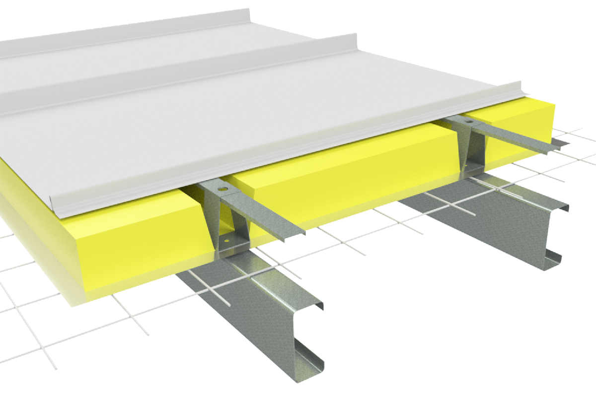
Non-Cyclonic Load Span Tables
The design pressures, allowable spans and design data for Boulevard™ have been determined from tests carried out in accordance with on the following Australian Standards:
- AS 1170.2:2011 Structural design actions Part 2: Wind actions
- AS 1562.1-2018 Design and installation of sheet roof and wall cladding Part 1: Metal
- AS 4040.0-1992 Methods of testing sheet roof and wall cladding Part 0: Introduction, list of methods and general requirements
- AS 4040.1-1992 Methods of testing sheet roof and wall cladding Method 1: Resistance concentrated loads
- AS4040.2-1992 Methods of testing sheet roof and wall cladding Method 2: Resistance to wind pressures for non-cyclone regions
- AS4040.3-1992 Methods of testing sheet roof and wall cladding Method 3: Resistance to wind pressures for cyclone regions
- AS4055:2012 Wind Loads for Housing
SA HB 39: 2015 Handbook - Installation code for metal roof and wall cladding National Construction Code of Australia
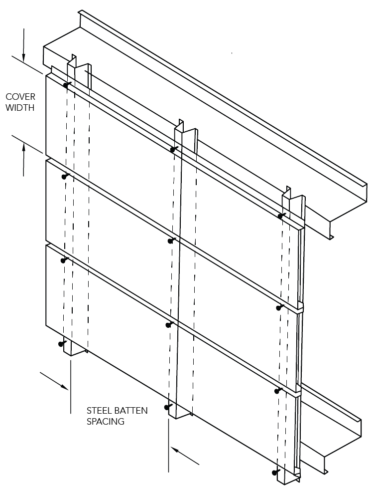
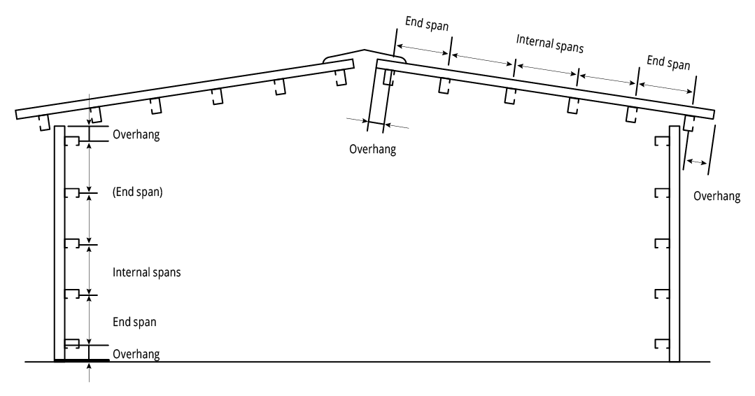
Figure BL NC 001 End Spans, Internal Spans and Overhangs
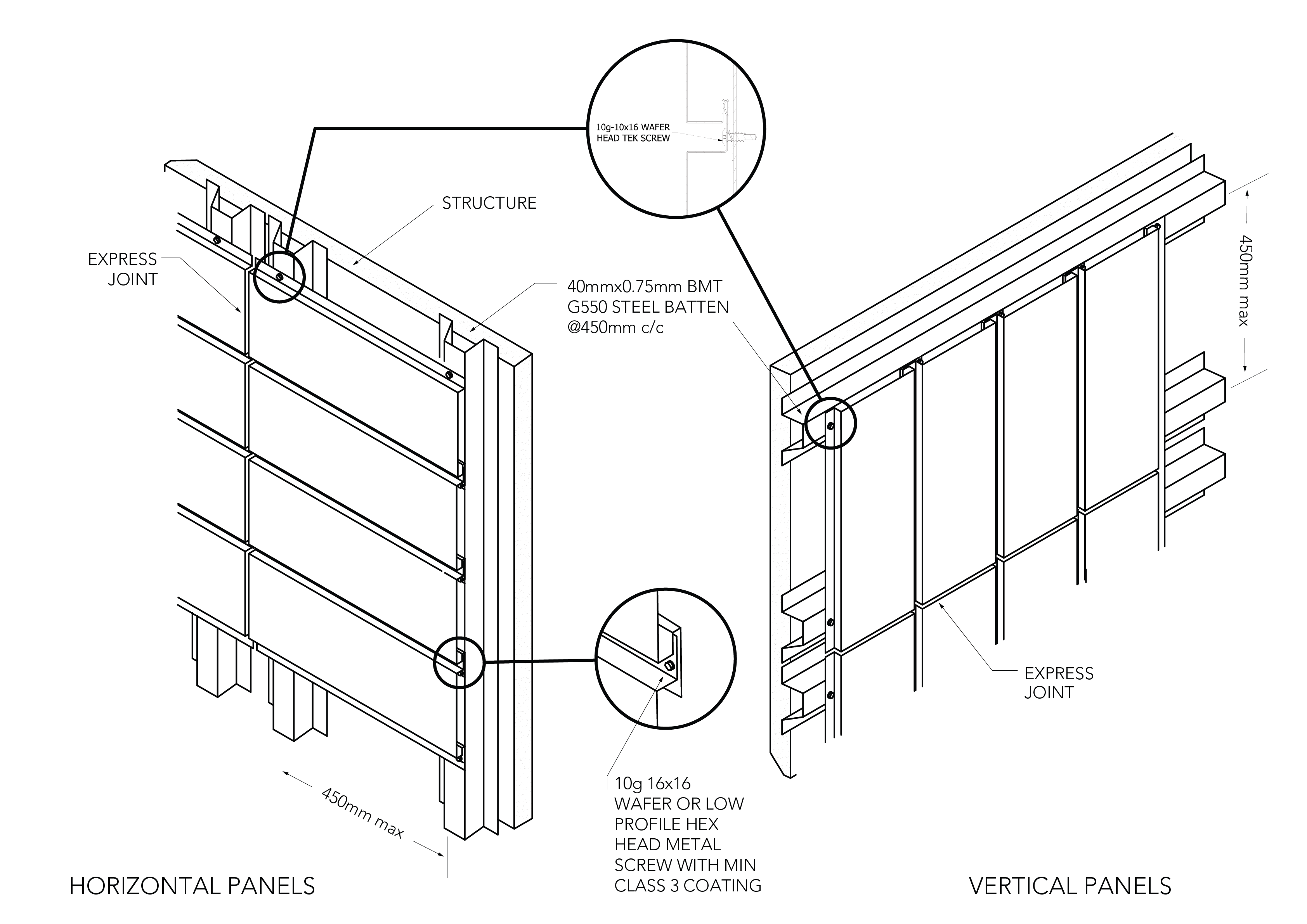
Figure BL ID NC 001
Vertical orientation on Metal Battens
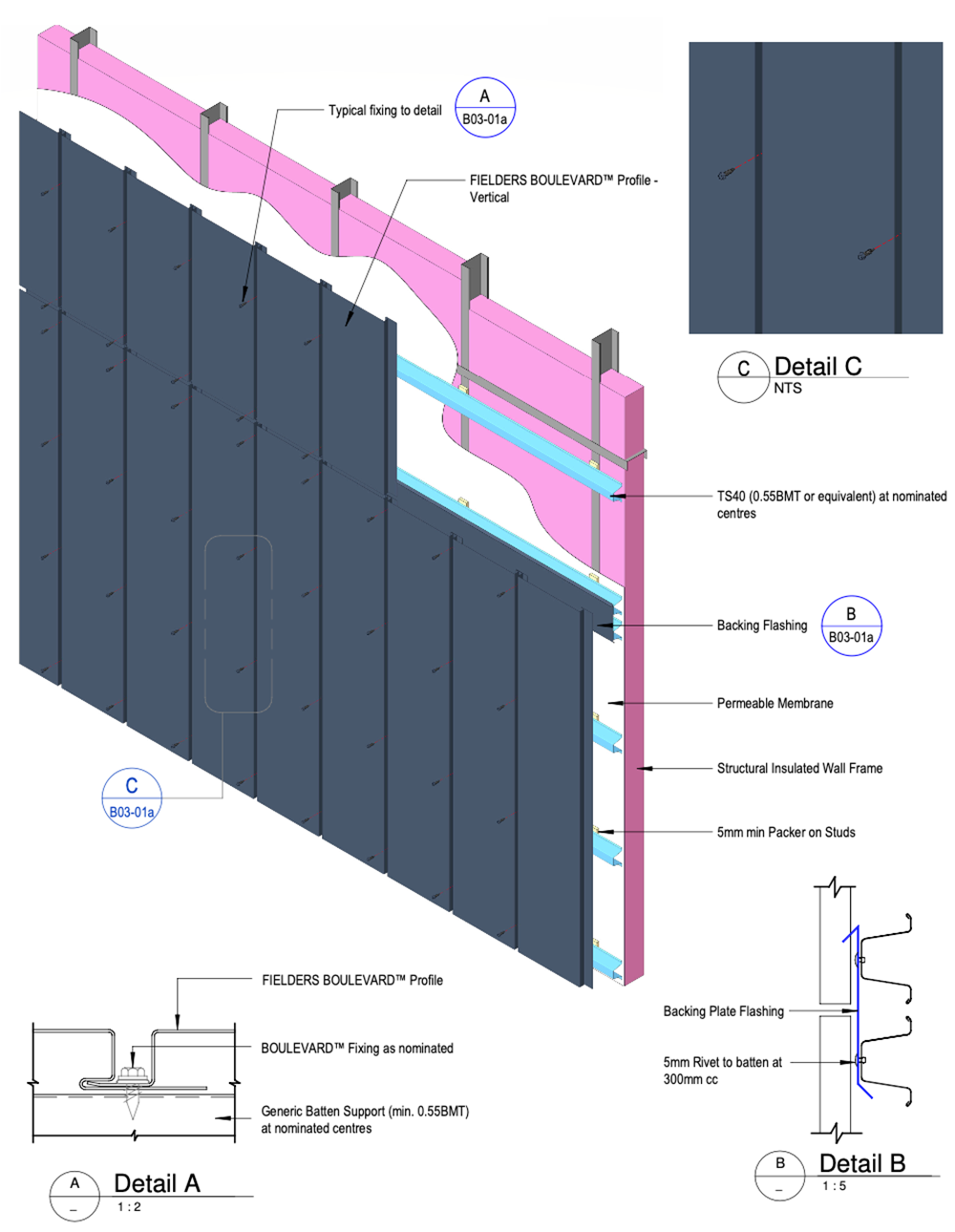
Figure BL ID NC - B03-01a - Vertical orientation on Metal Battens
Horizontal orientation on Metal Battens
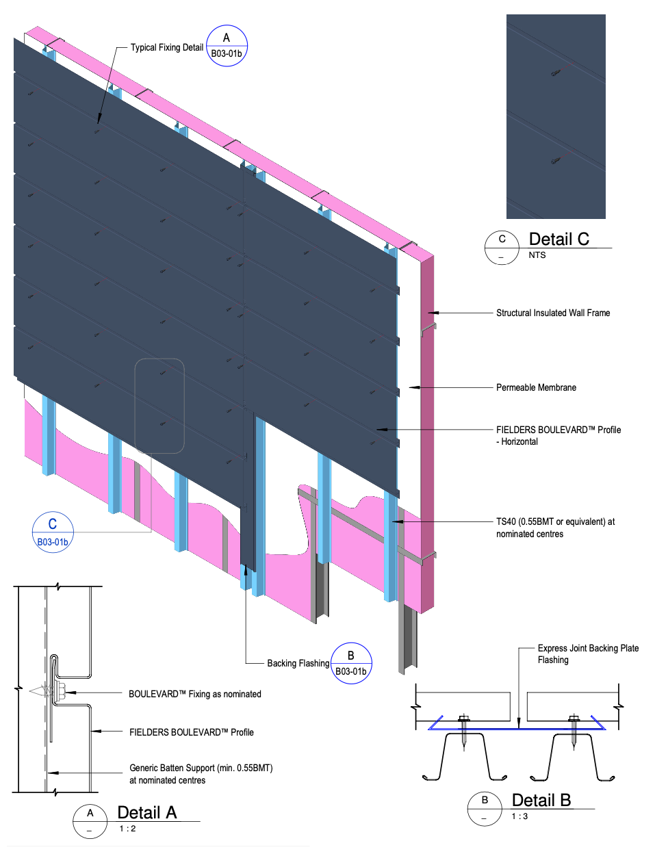
Figure BL ID NC - B03-01b - Horizontal orientation on Metal Battens
Vertical orientation on Ply
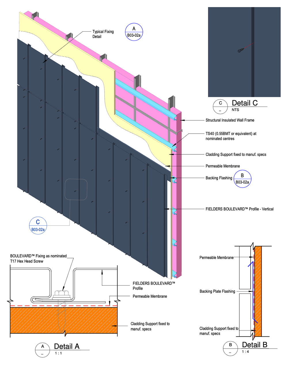
Figure BL ID NC - B03-02a - Vertical orientation on Ply
Horizontal orientation on Ply

Figure BL ID NC - B03-02b - Horizontal orientation on Ply
Horizontal Fix - Plan View
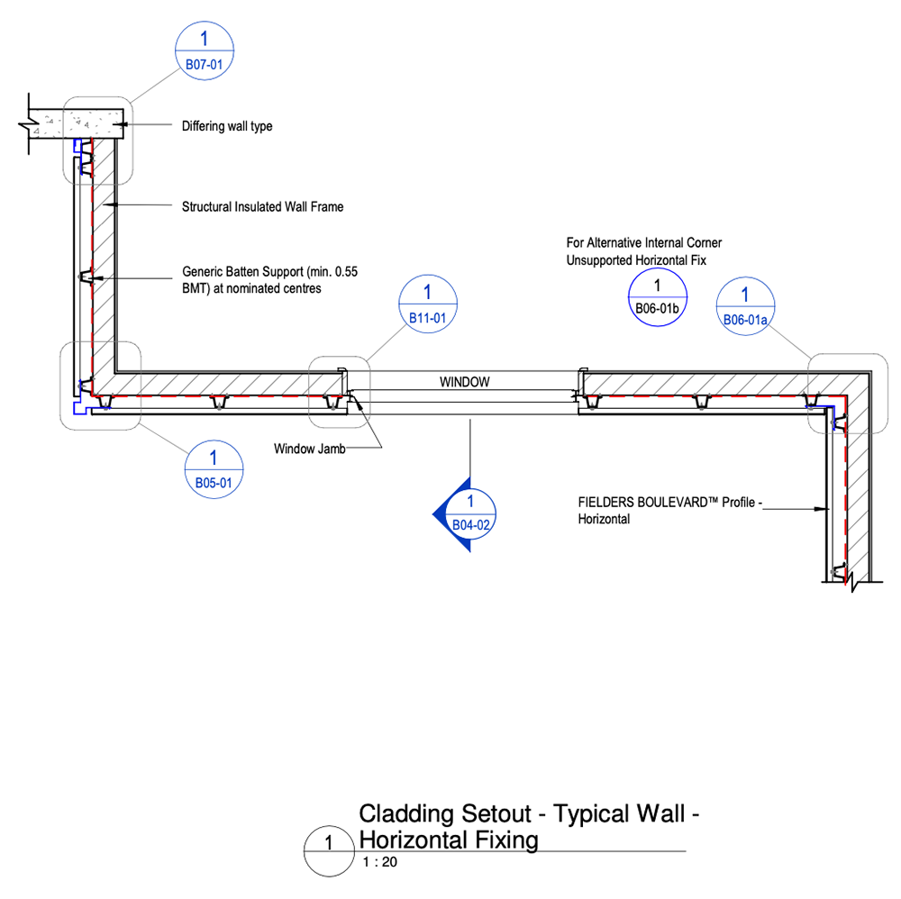
Figure BL ID NC - B04-01 - Horizontal Fix - Plan View
Horizontal Fix - Sectional View
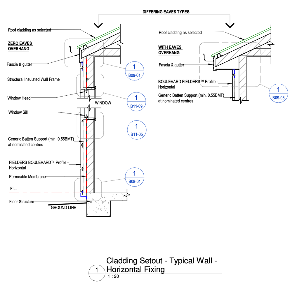
Figure BL ID NC - B04-02 - Horizontal Fix - Sectional View
Horizontal Fix - External Corner Detail
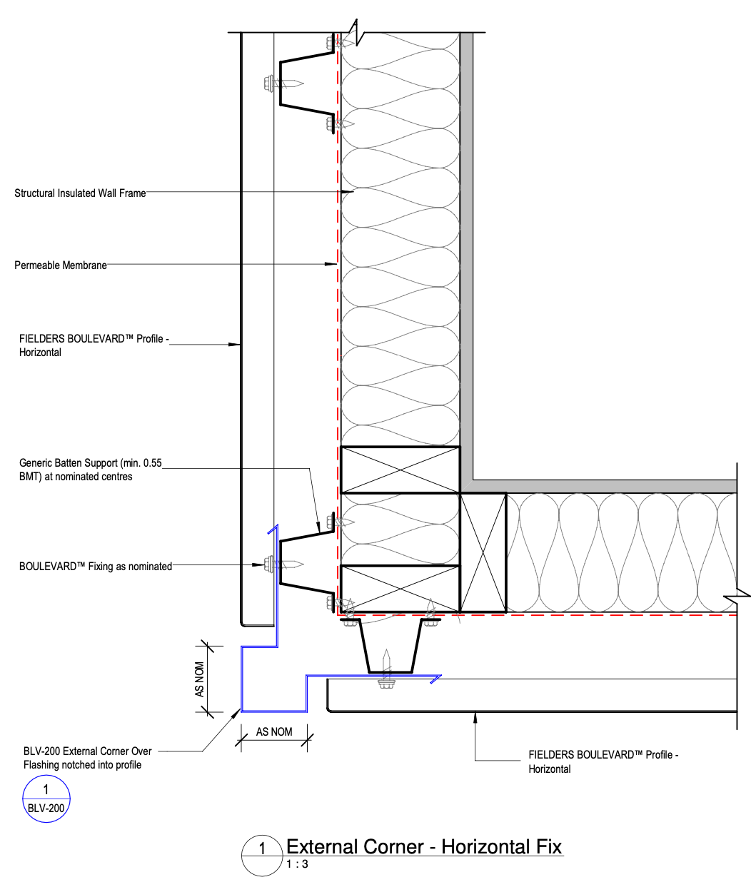
Figure BL ID NC - B05-01 - Horizontal Fix - External Corner Detail
Horizontal Fix - Internal Corner Detail - Option 1
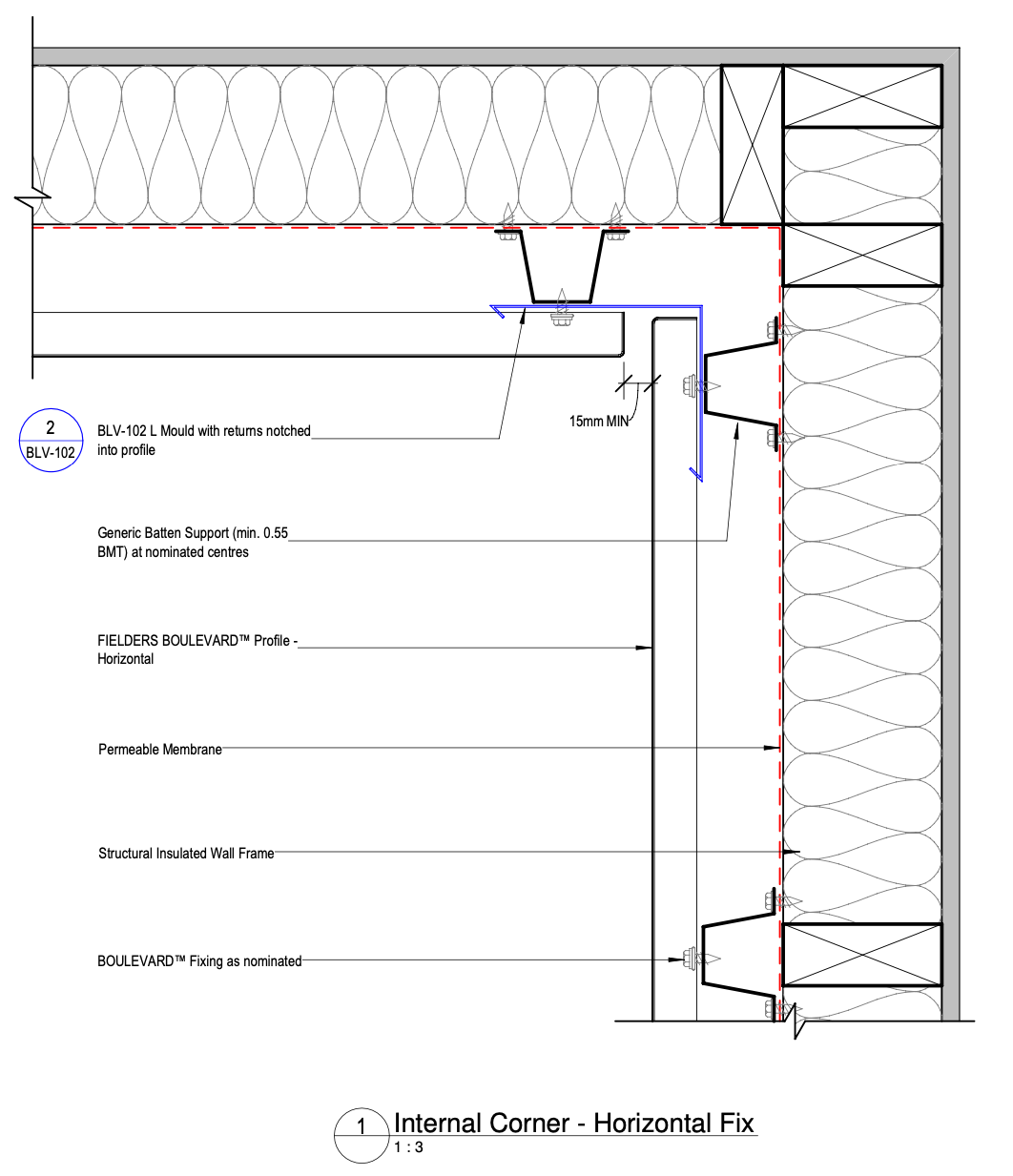
Figure BL ID NC - B06-01a - Horizontal Fix - Internal Corner Detail - Option 1
Horizontal Fix - Internal Corner Detail - Option 2
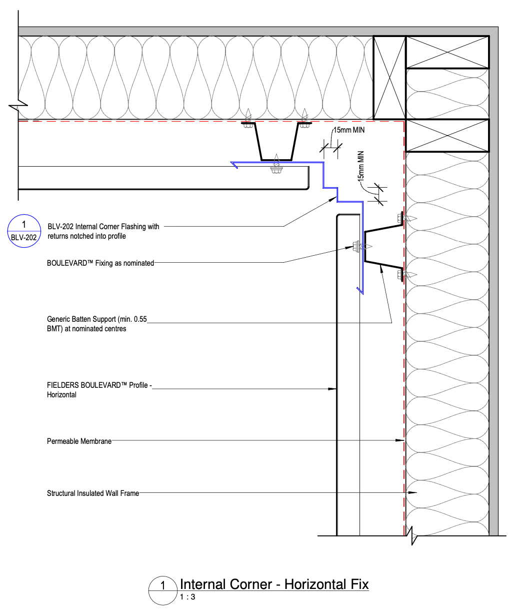
Figure BL ID NC - B06-01b - Horizontal Fix - Internal Corner Detail - Option 2
Horizontal Fix - Wall Closure Detail
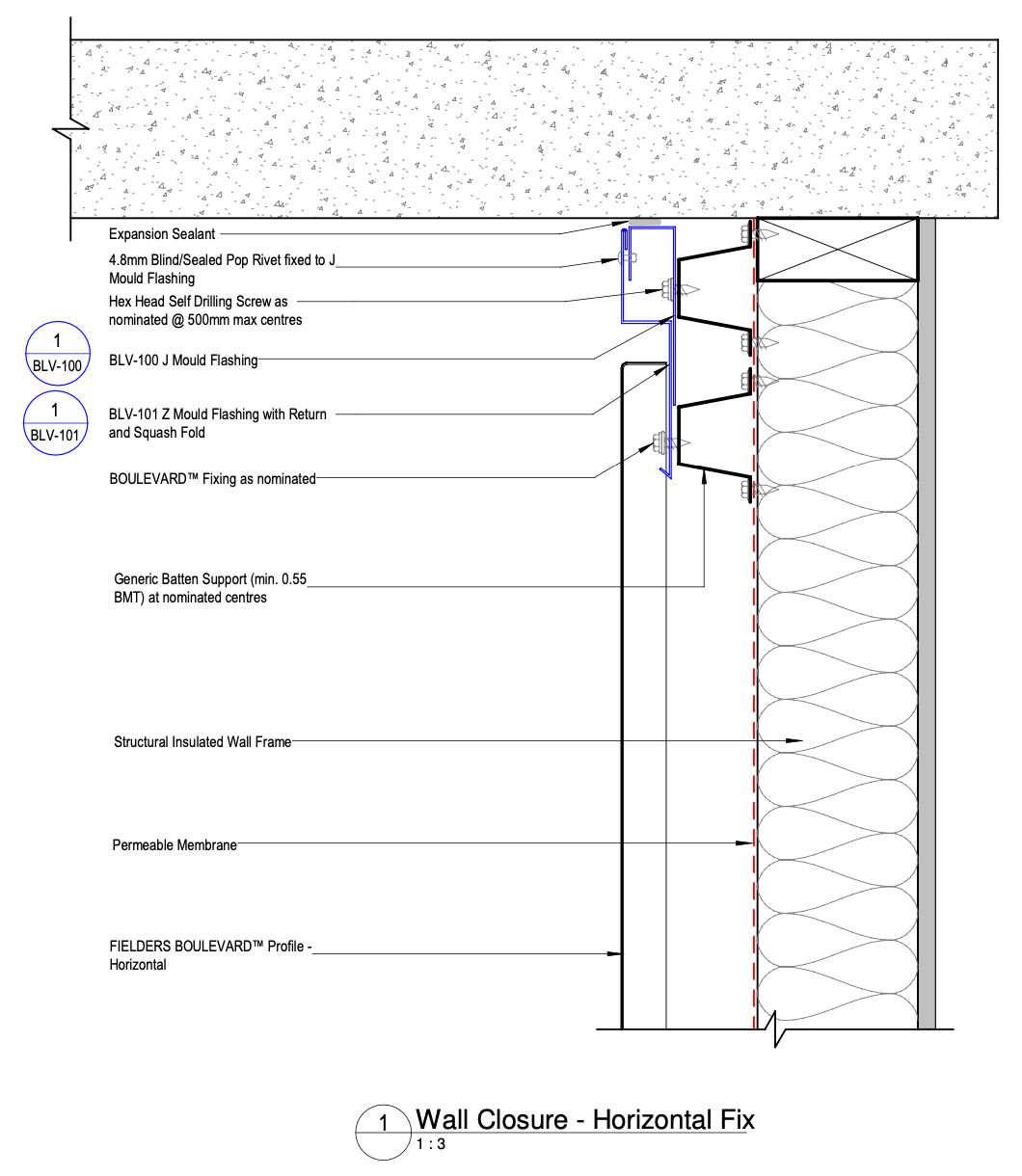
Figure BL ID NC - B07-01 - BOULEVARD™ Horizontal Fix - Wall Closure Detail
Horizontal Fix - Wall Base Detail
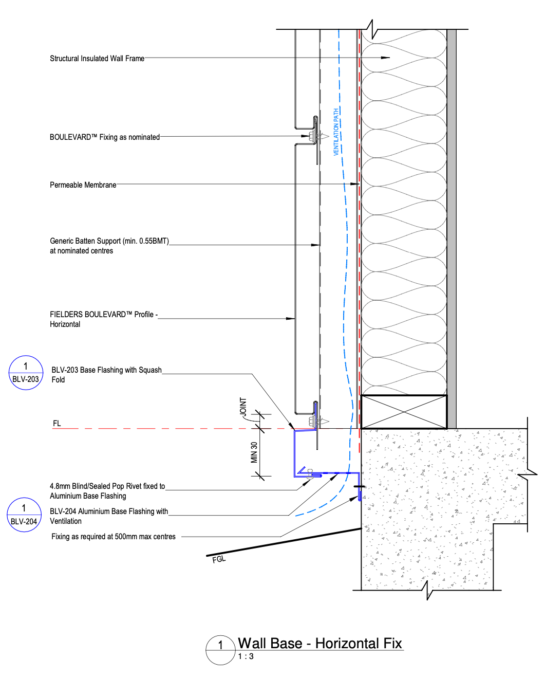
Figure BL ID NC - B08-01 - Horizontal Fix - Wall Base Detail
Horizontal Fix - Top of Wall Eave Detail - Zero Overhang
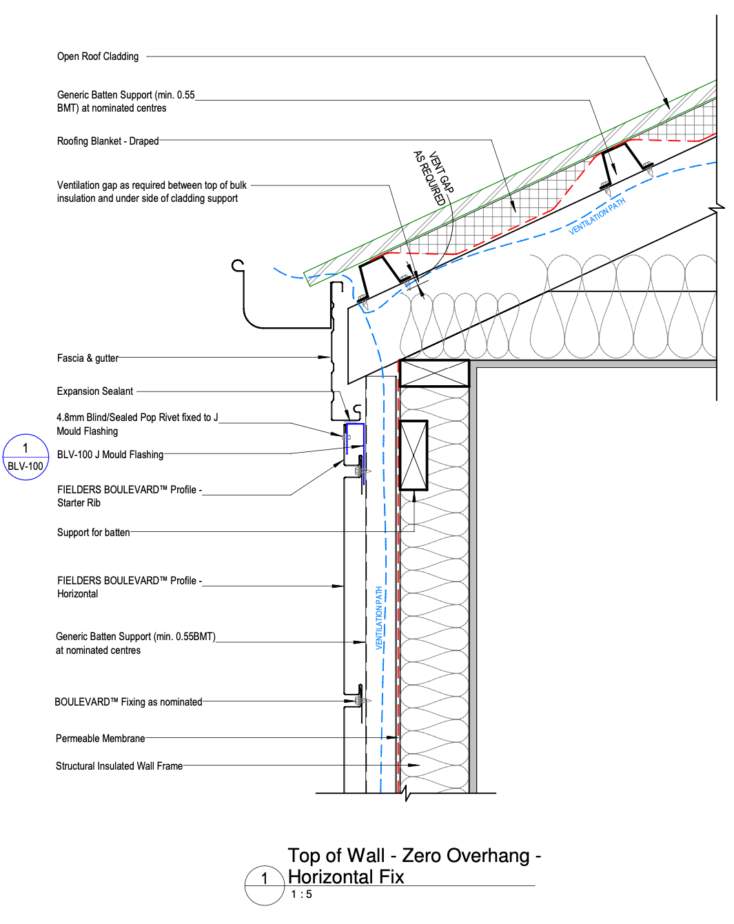
Figure BL ID NC - B09-01 - Horizontal Fix - Top of Wall Eave Detail - Zero Overhang
Horizontal Fix - Top of Wall Eave Detail - Overhang
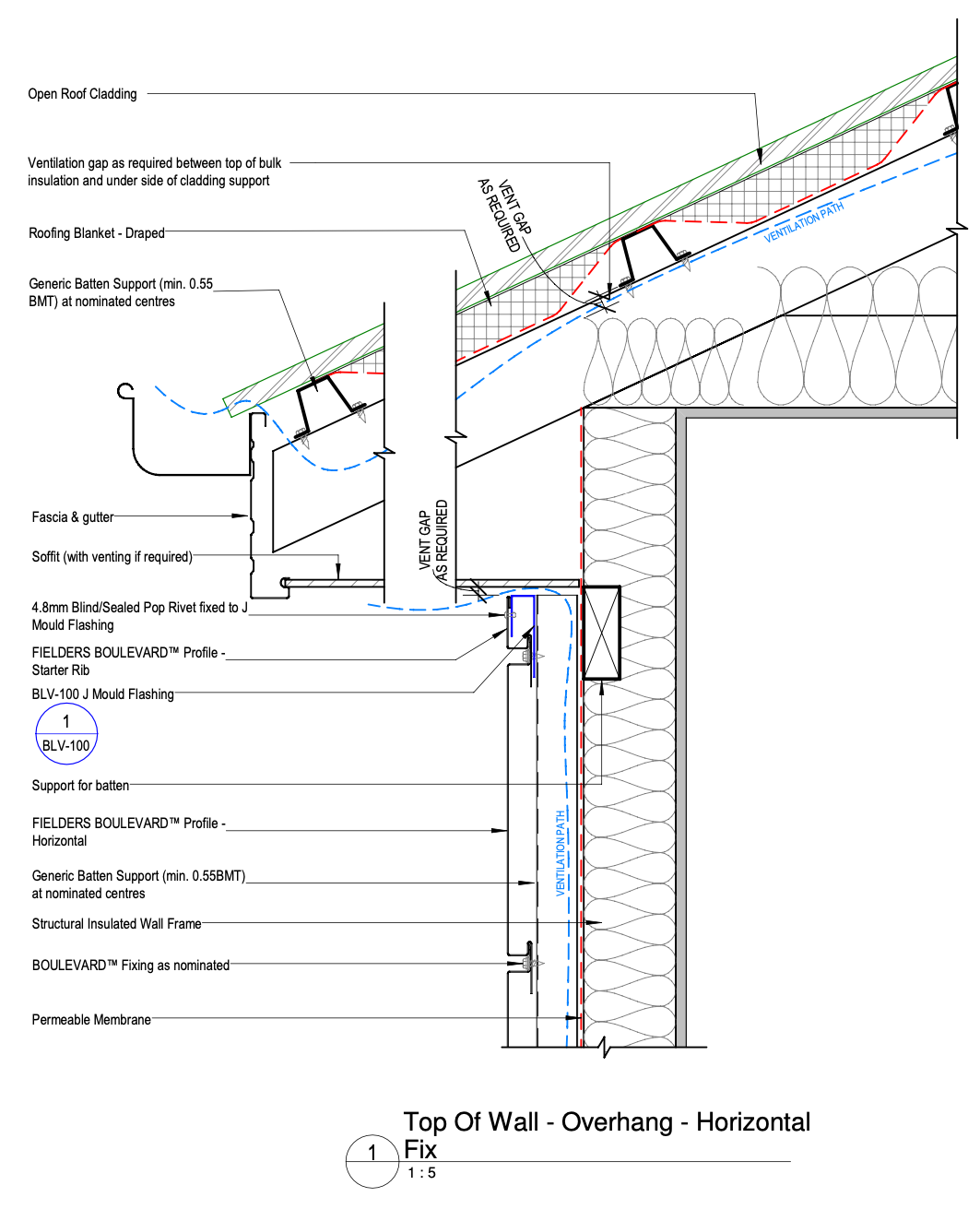
Figure BL ID NC - B09-05 - Horizontal Fix - Top of Wall Eave Detail - Overhang
Horizontal Fix - Window Sill Detail
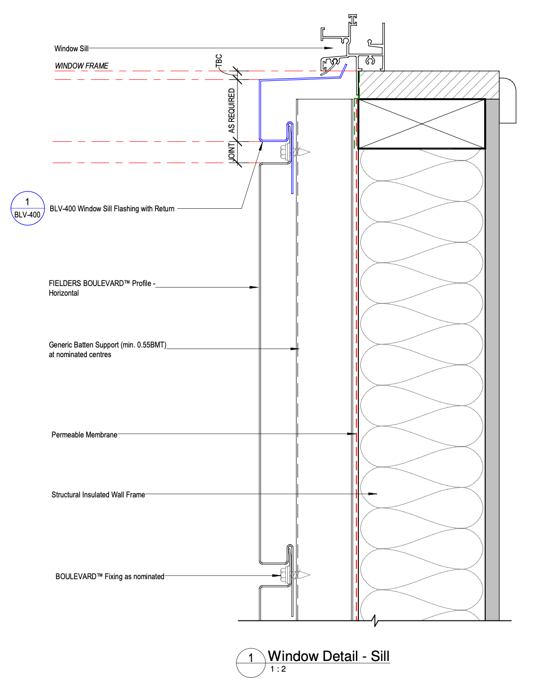
Figure BL ID NC - B11-05 - Horizontal Fix - Window Sill Detail
Horizontal Fix - Window Head Detail
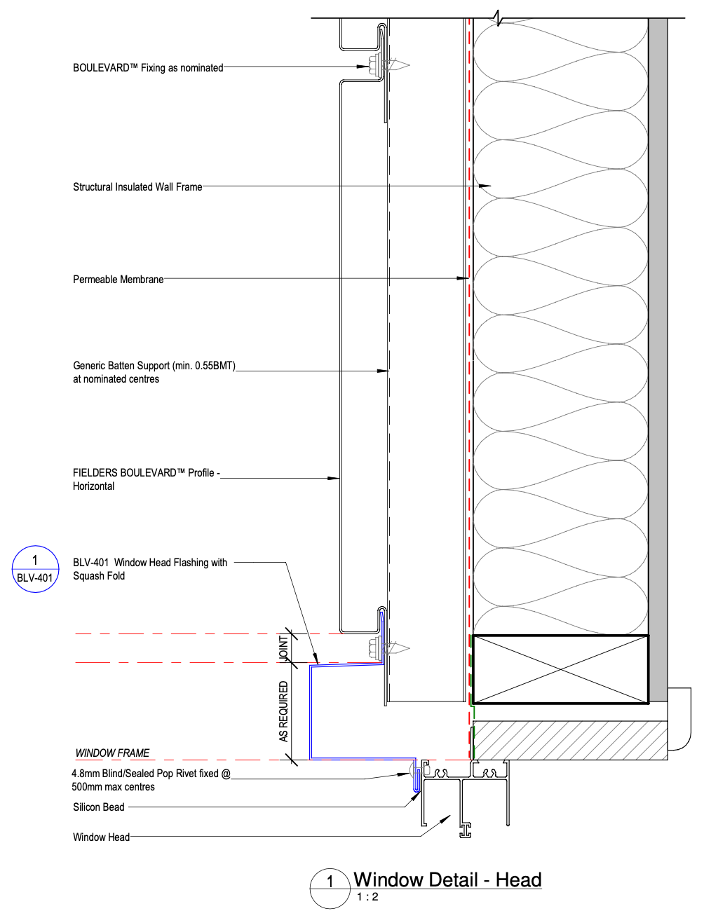
Figure BL ID NC - B11-09 - Horizontal Fix - Window Head Detail
Horizontal Fix - Window Jamb Detail
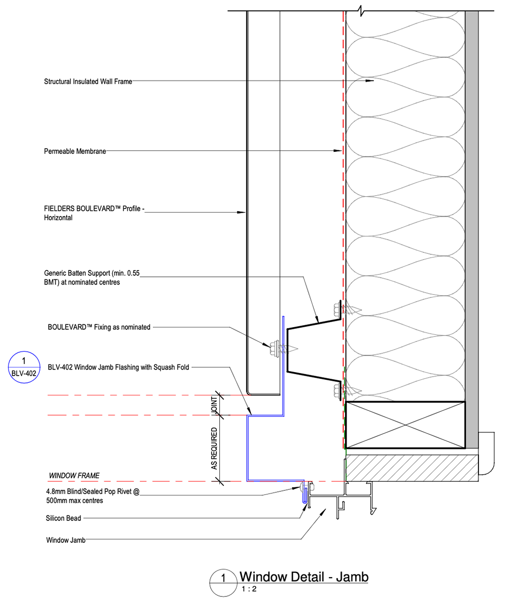
Figure BL ID NC - B11-01 - Horizontal Fix - Window Jamb Detail
Vertical Fix - Typical Wall Cladding Setout
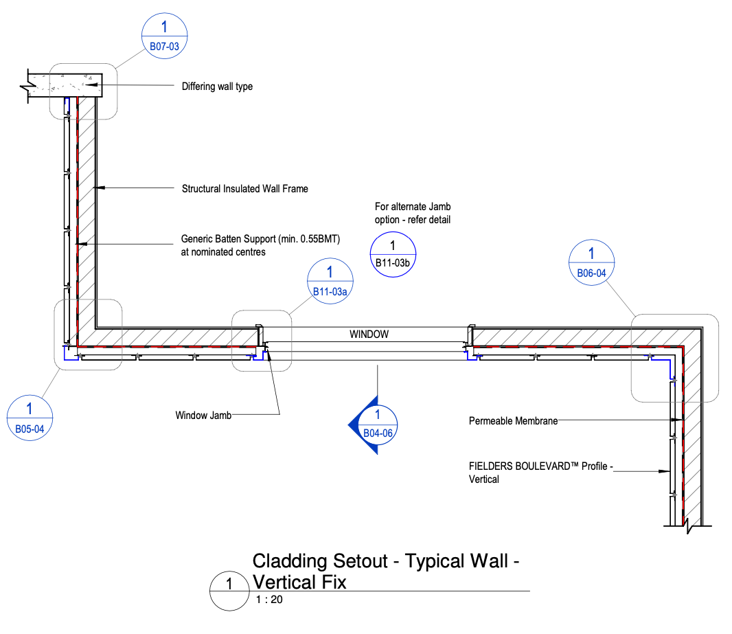
Figure BL ID NC - B04-05 - Vertical Fix - Typical Wall Cladding Setout
Vertical Fix - Typical Wall Cladding Setout
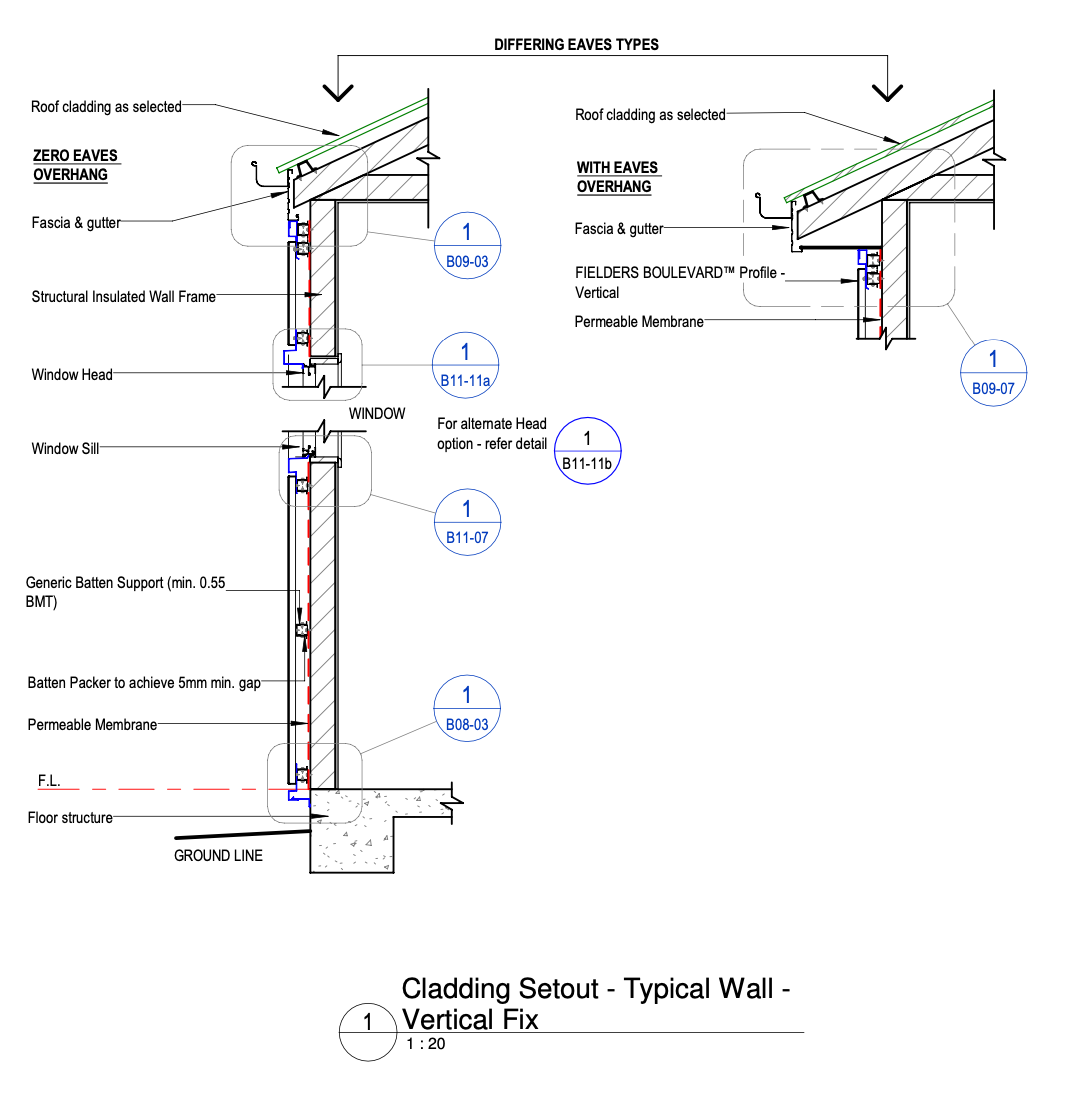
Figure BL ID NC - B04-06 - Vertical Fix - Typical Wall Cladding Setout
Vertical Fix - External Corner Detail - M-M
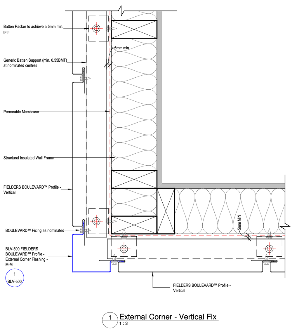
Figure BL ID NC - B05-04 - Vertical Fix - External Corner Detail - M-M
Vertical Fix - Internal Corner Detail - M-M
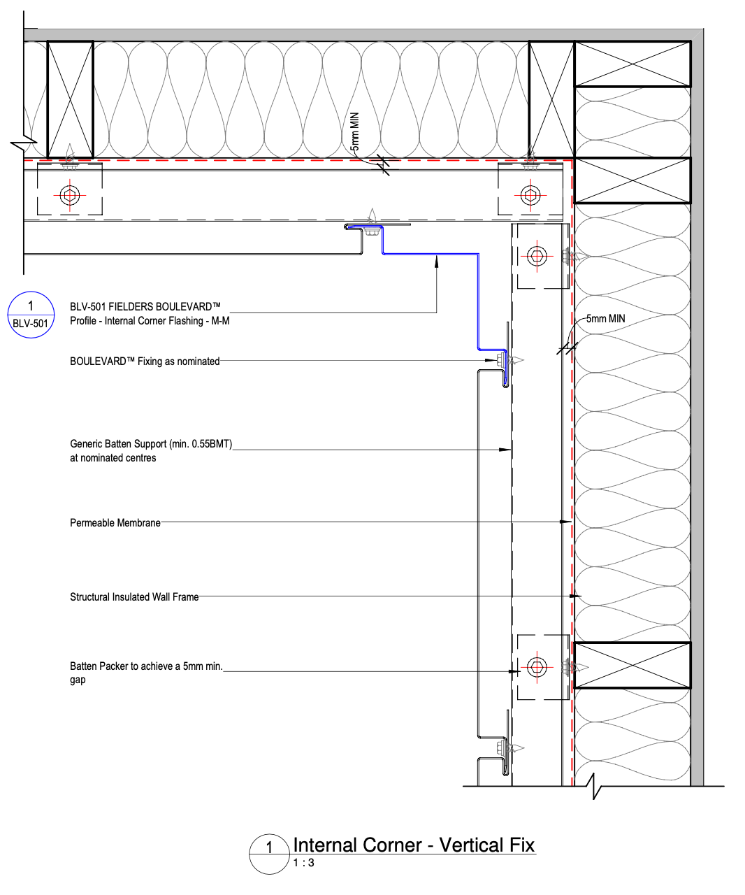
Figure BL ID NC - B06-04 - Vertical Fix - Internal Corner Detail - M-M
Vertical Fix - Wall Closure Detail
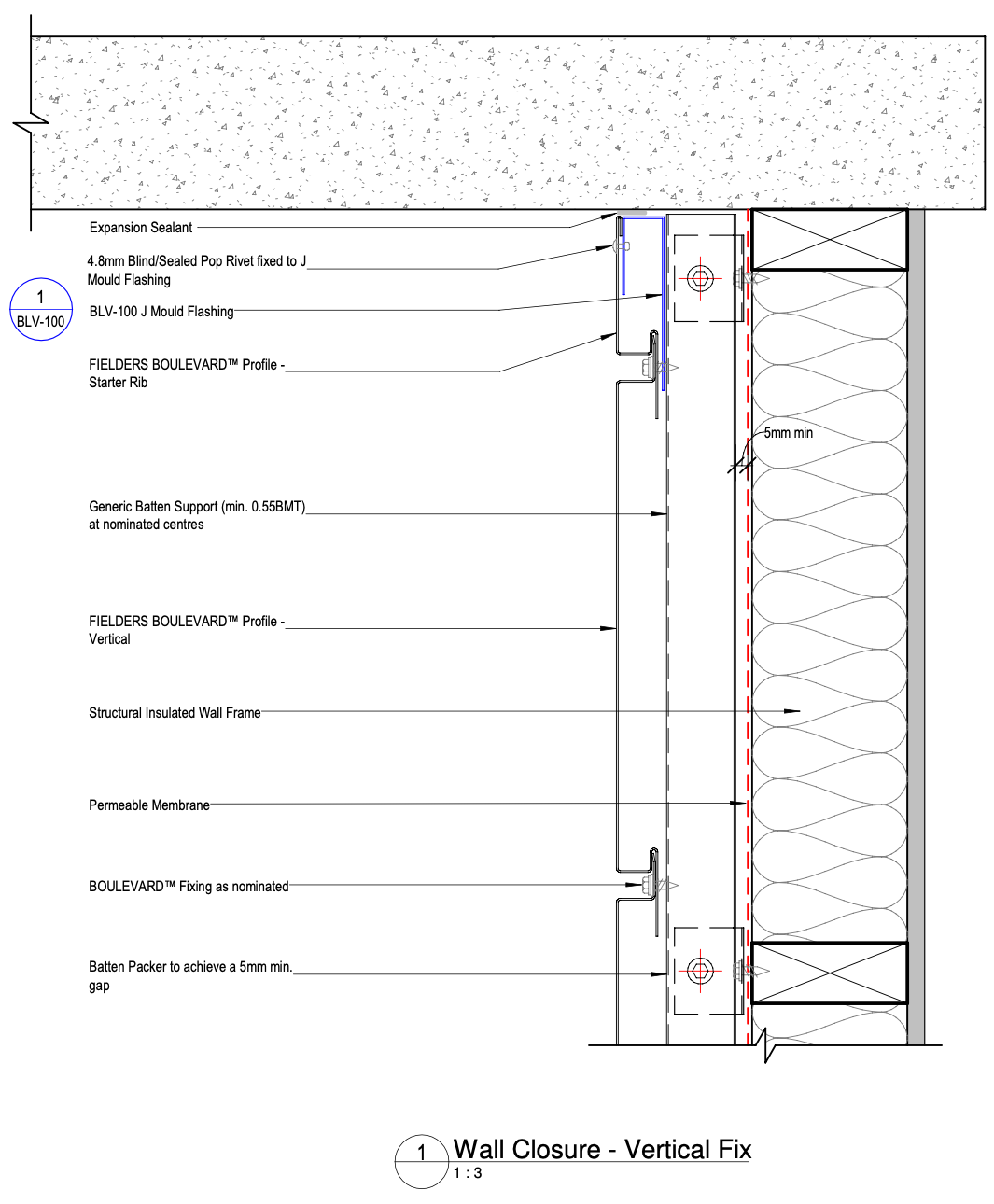
Figure BL ID NC - B07-03 - Vertical Fix - Wall Closure Detail
Vertical Fix - Wall Base Detail
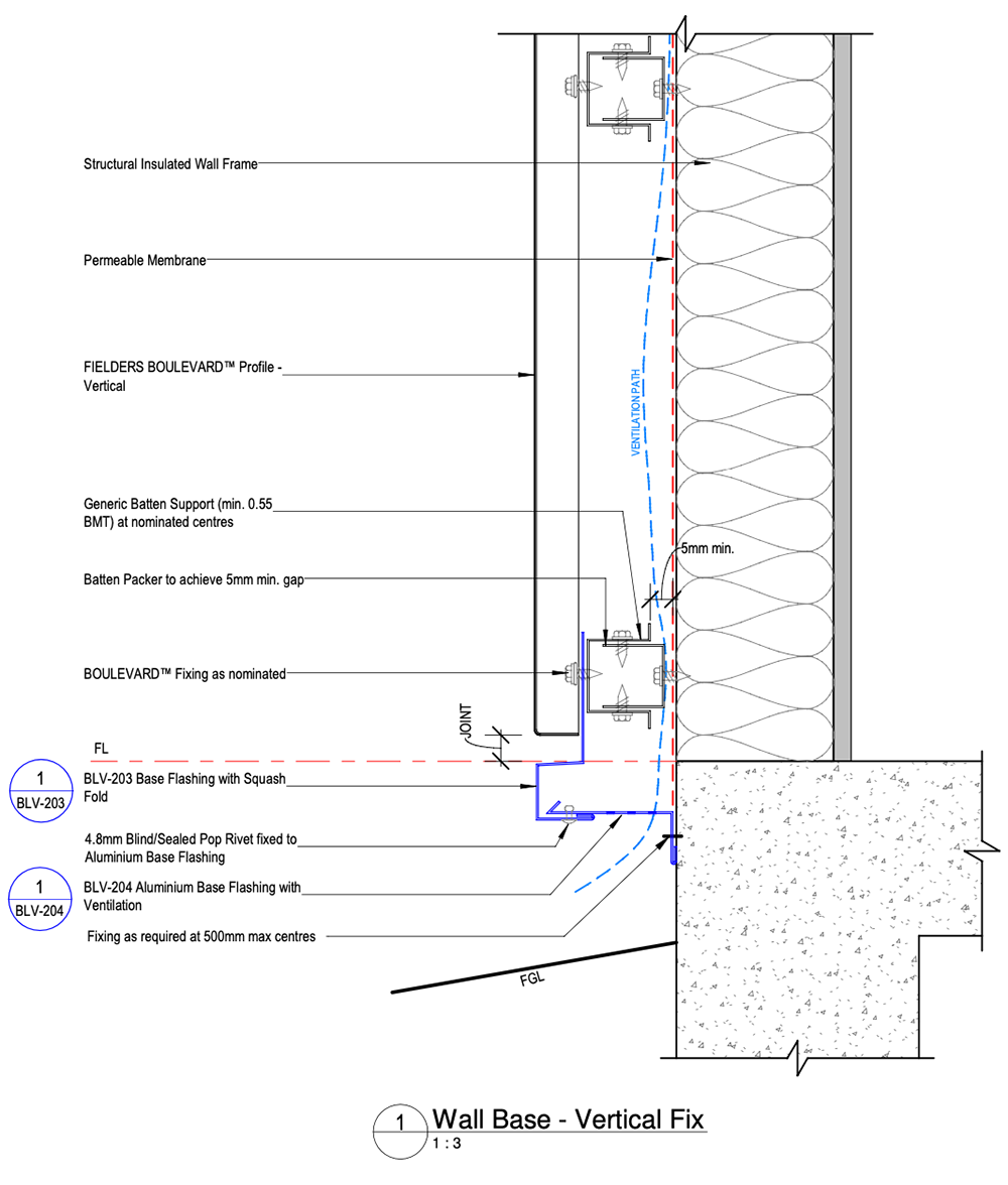
Figure BL ID NC - B08-03 - Vertical Fix - Wall Base Detail
Vertical Fix - Top of Wall Eave Detail - Zero Overhang
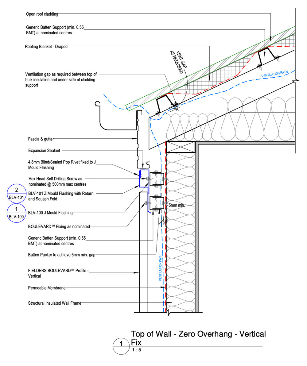
Figure BL ID NC - B09-03 - Vertical Fix - Top of Wall Eave Detail - Zero Overhang
Vertical Fix - Top of Wall Eave Detail - Overhang
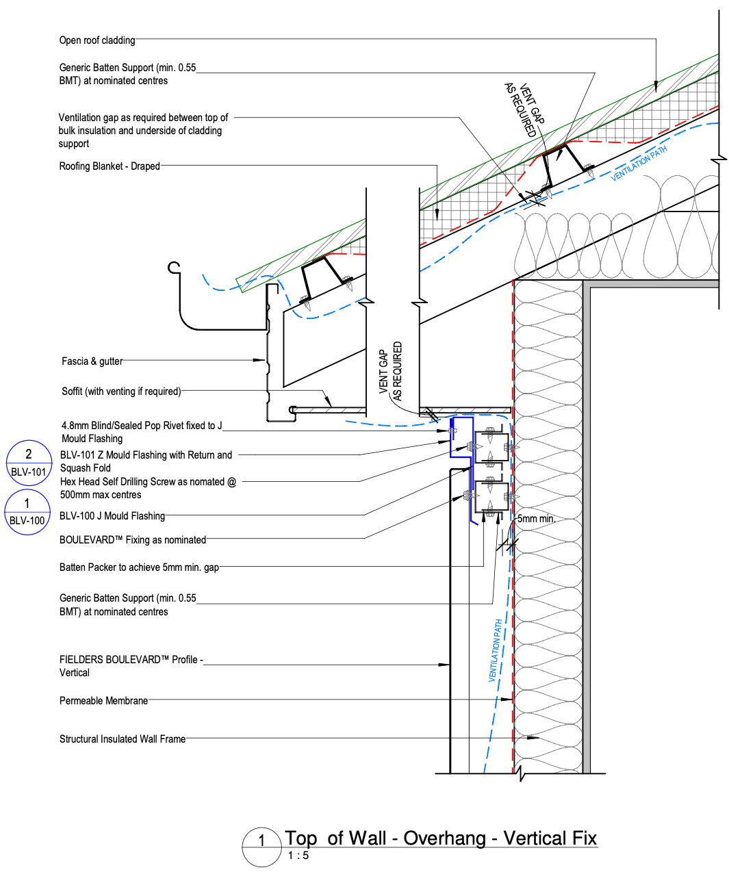
Figure BL ID NC - B09-07 - Vertical Fix - Top of Wall Eave Detail - Overhang
Vertical Fix - Window Jamb Detail - Male
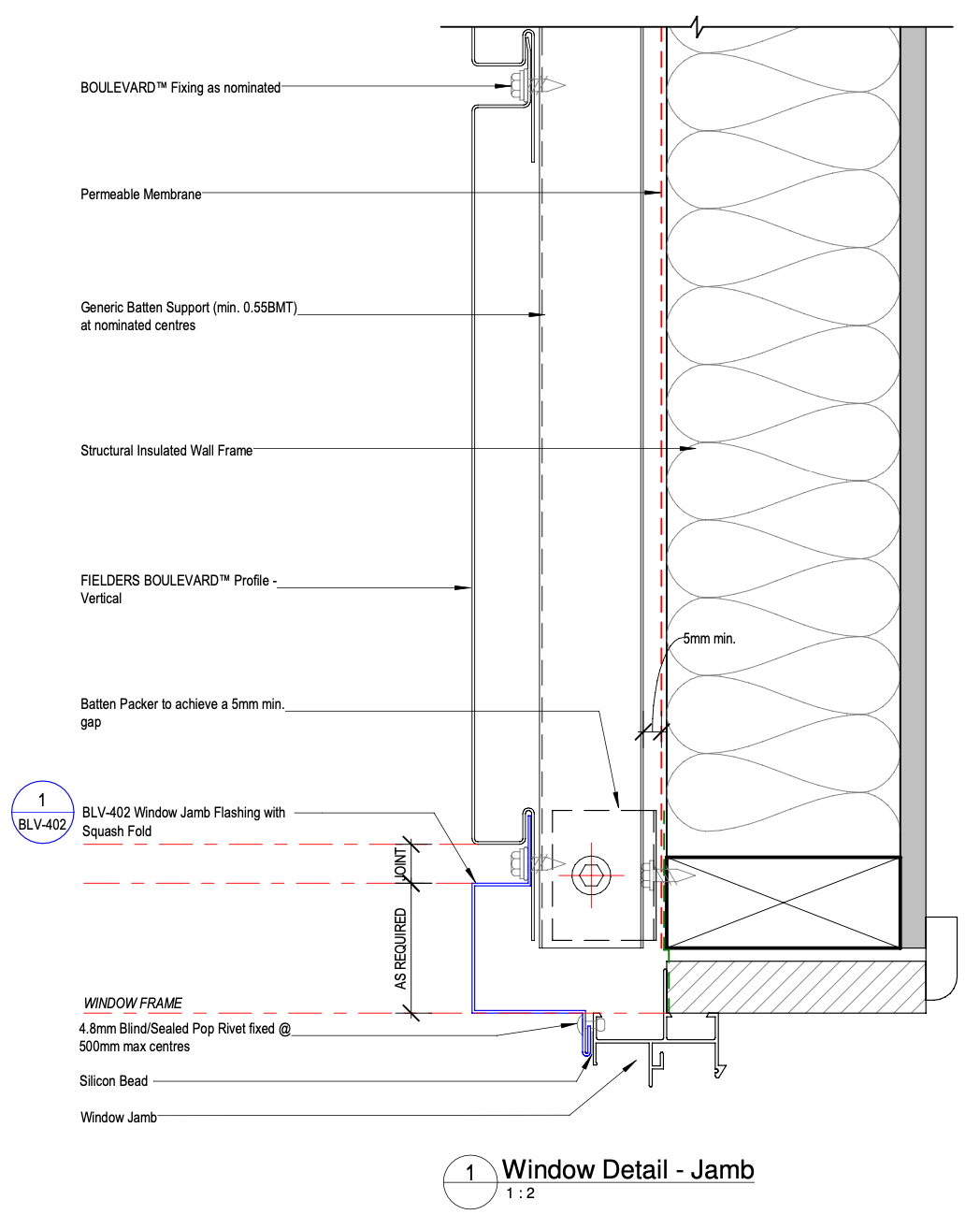
Figure BL ID NC - B11-03a - Vertical Fix - Window Jamb Detail - Male
Vertical Fix - Window Jamb Detail - Female
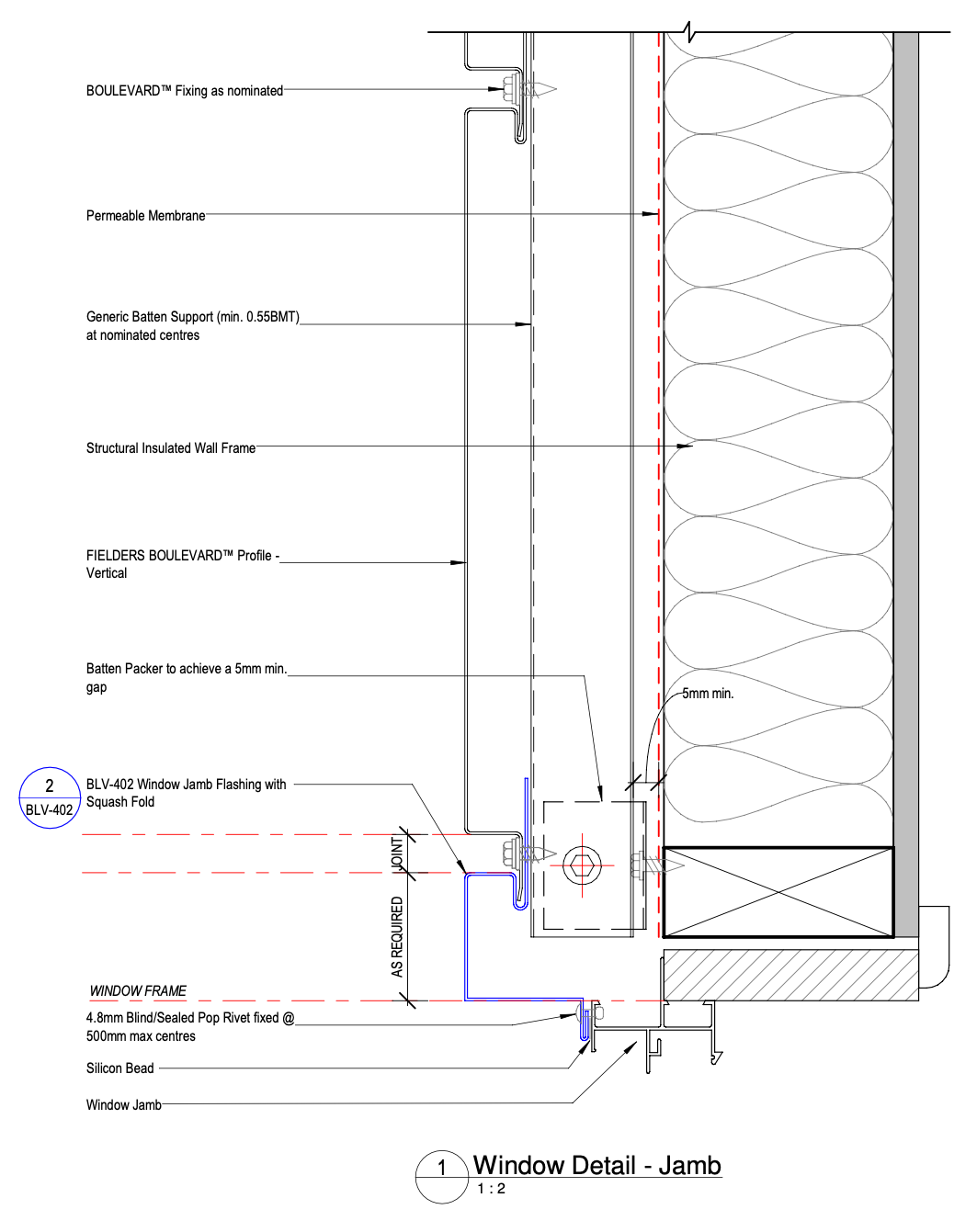
Figure BL ID NC - B11-03b - Vertical Fix - Window Jamb Detail - Female
Vertical Fix - Window Sill Detail
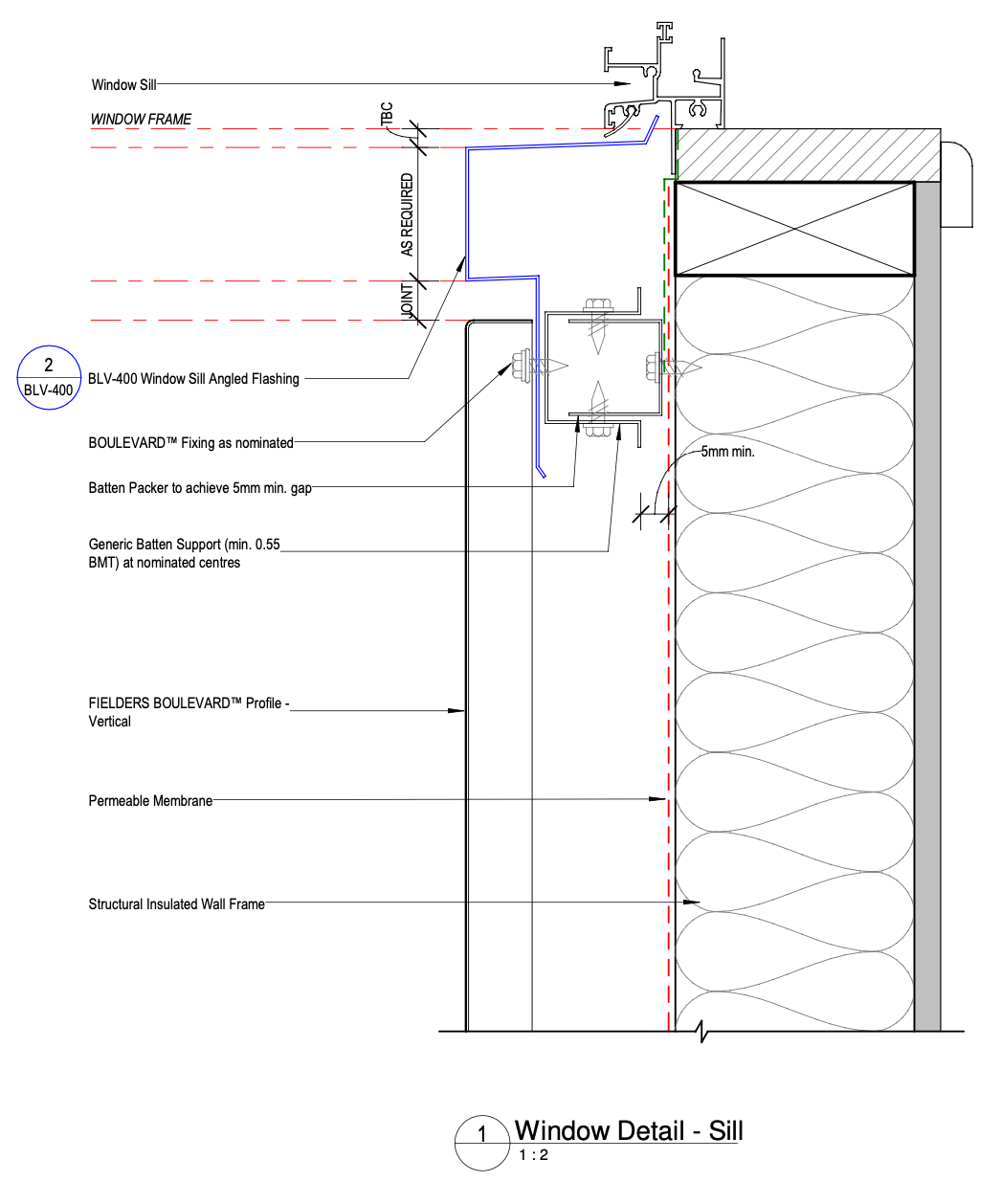
Figure BL ID NC - B11-07 - Vertical Fix - Window Sill Detail
Vertical Fix - Window Head Detail - Option 1
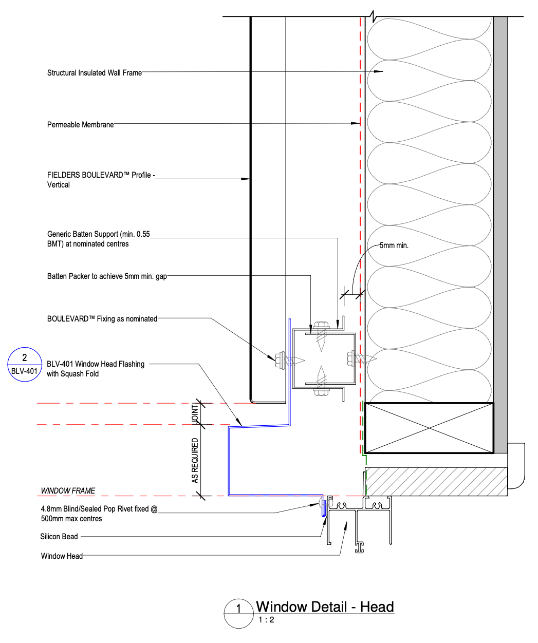
Figure BL ID NC - B11-11a - Vertical Fix - Window Head Detail - Option 1
Vertical Fix - Window Head Detail - Option 2
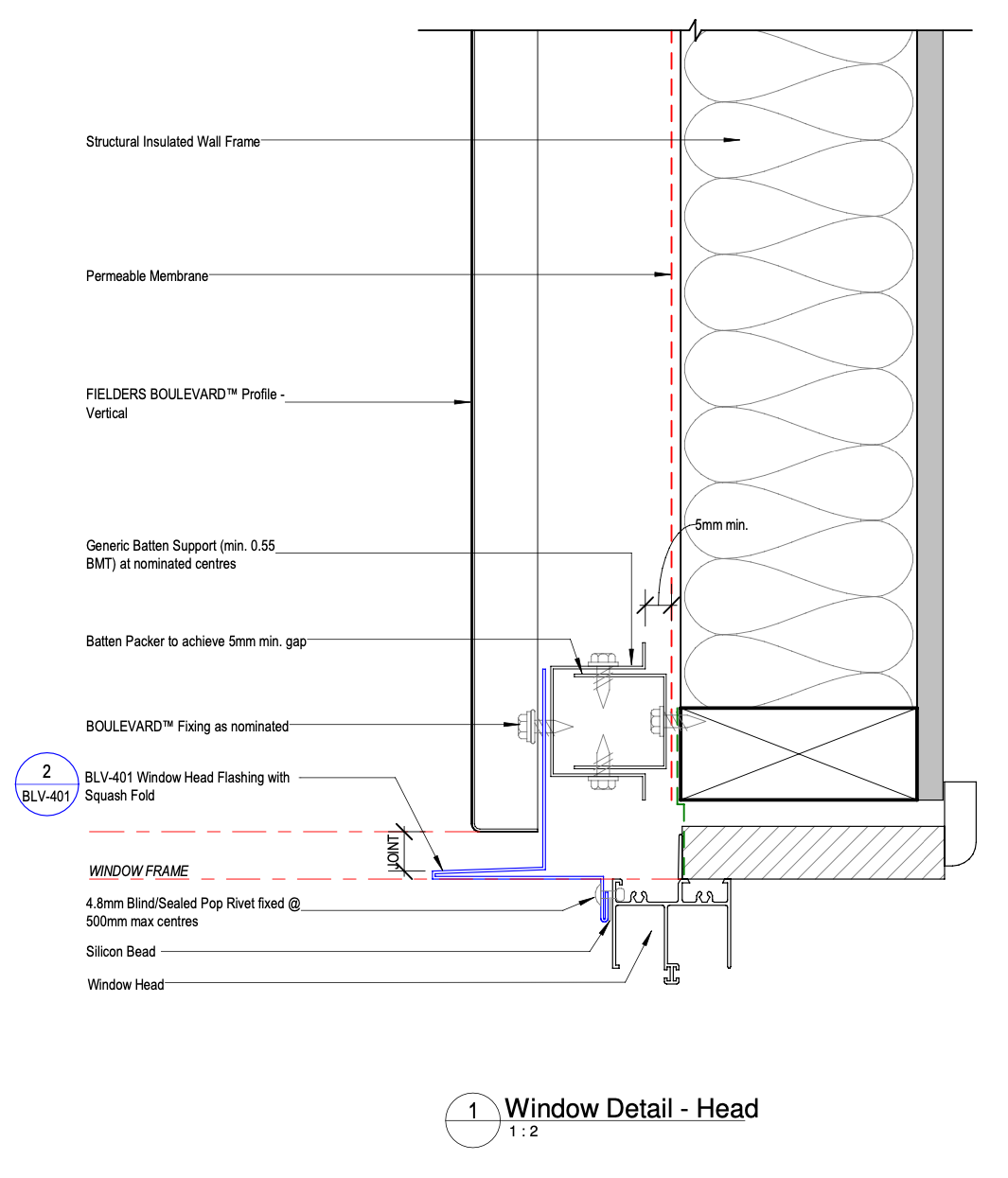
Figure BL ID NC - B11-11b - Vertical Fix - Window Head Detail - Option 2
Vertical Fix - Window Sill Detail
Figure BL ID NC - B11-07 - Vertical Fix - Window Sill Detail
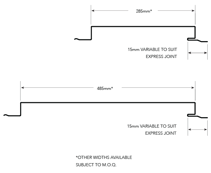
Typical Panel Section
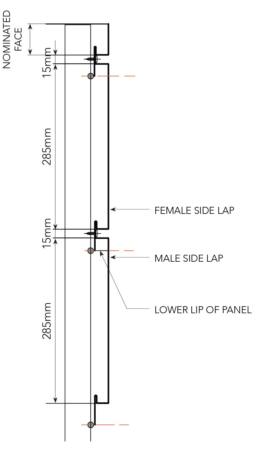
Figure BL ID NC 023
Panel Marking Matrix
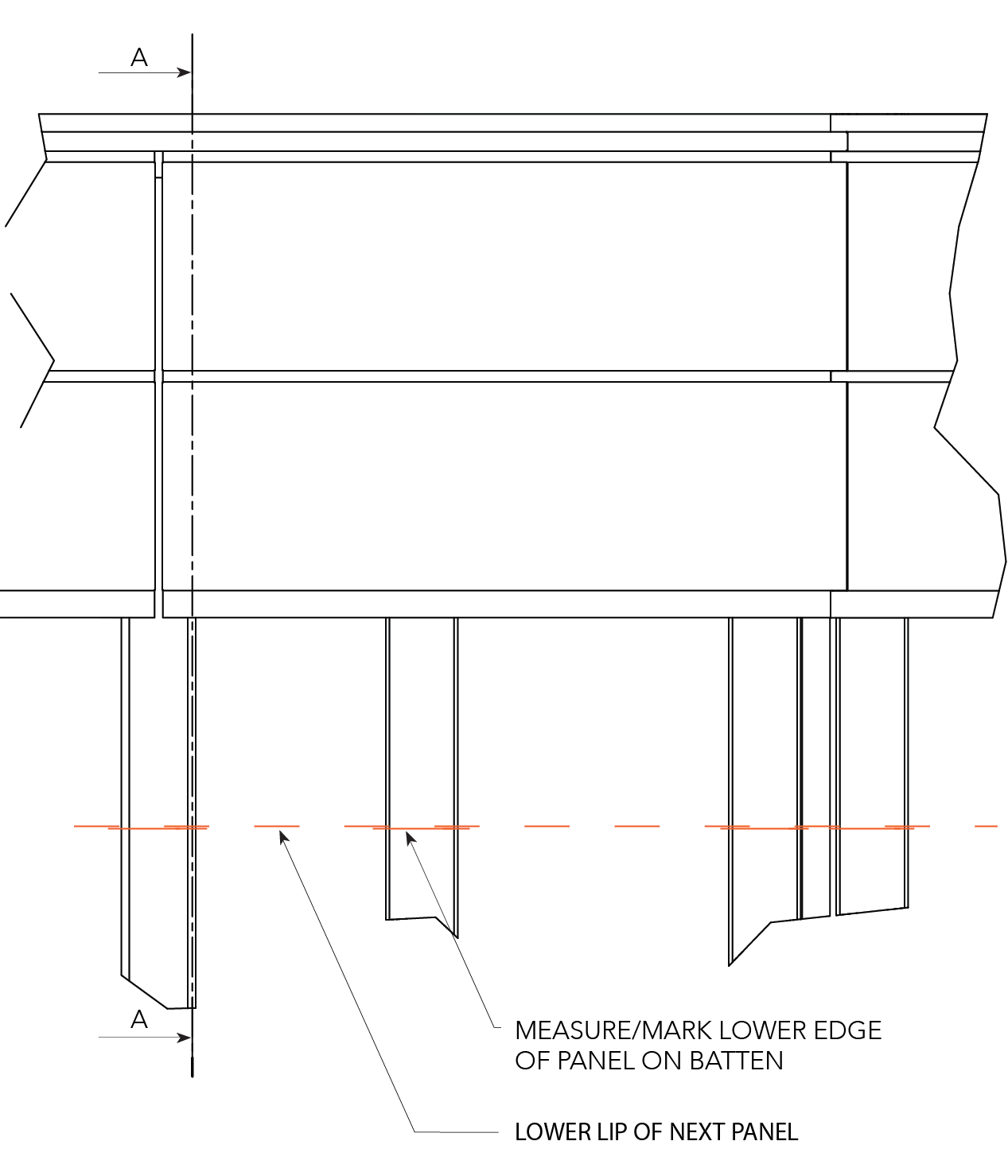
Figure BL ID NC 024
Backing Plates
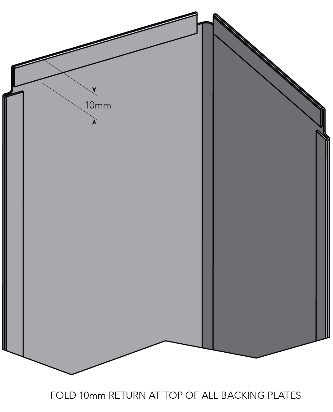
Figure BL ID NC 025
Foam Infills
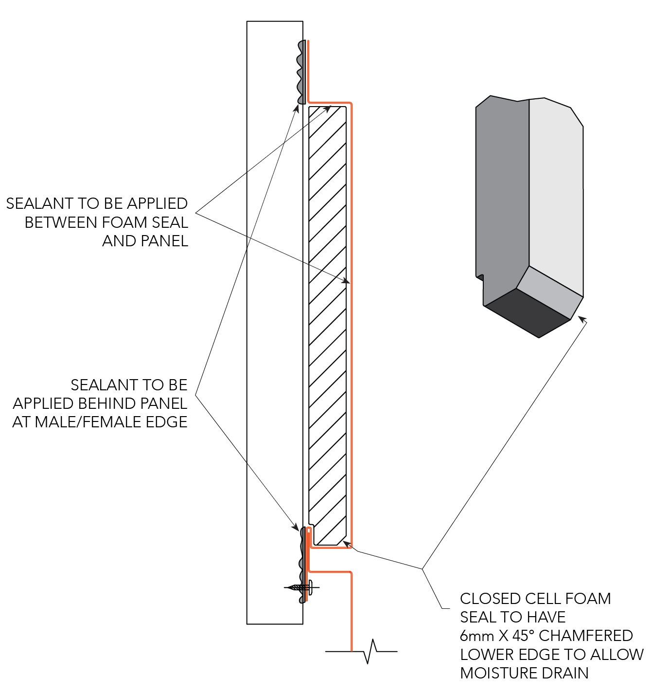
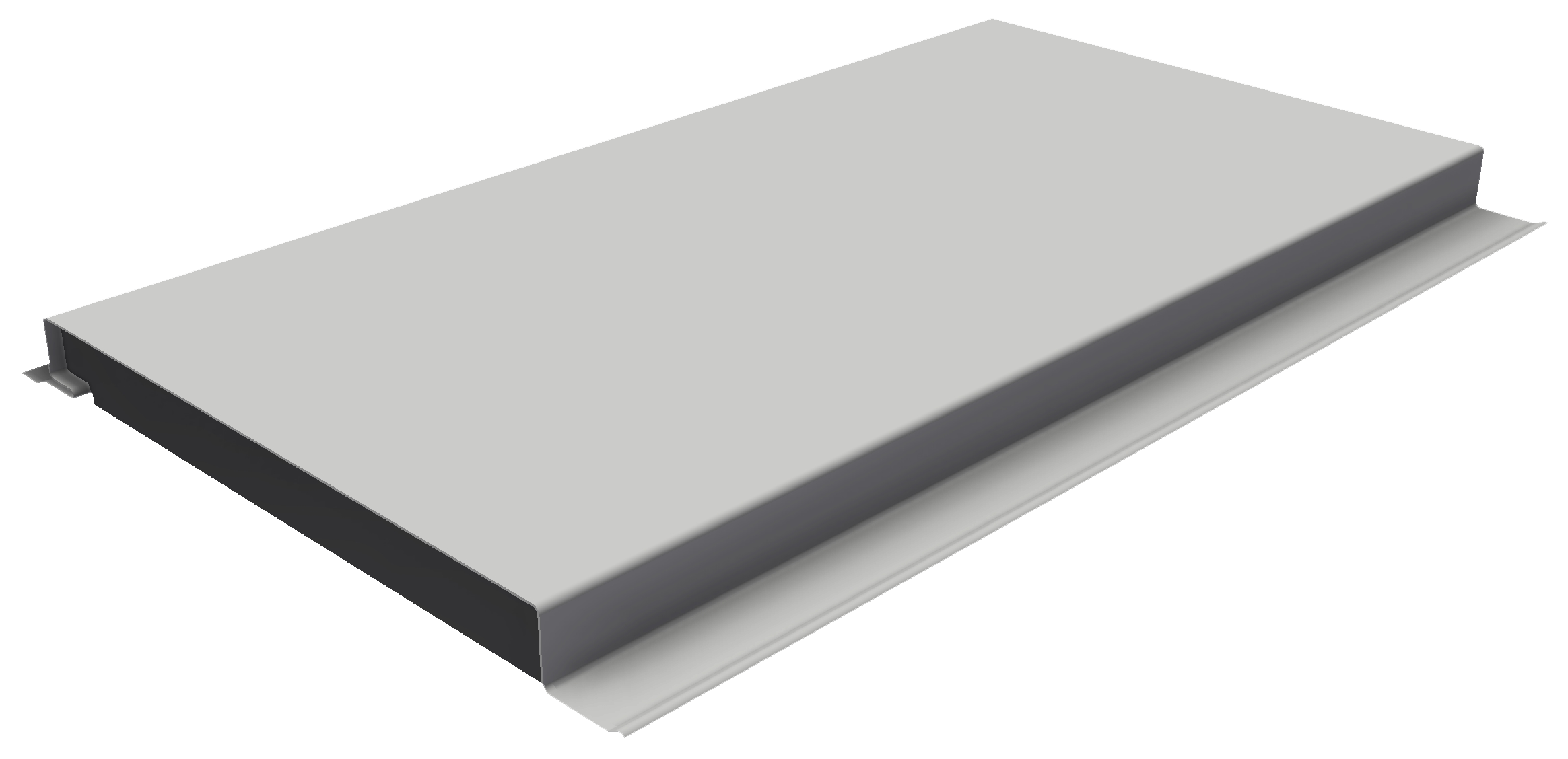
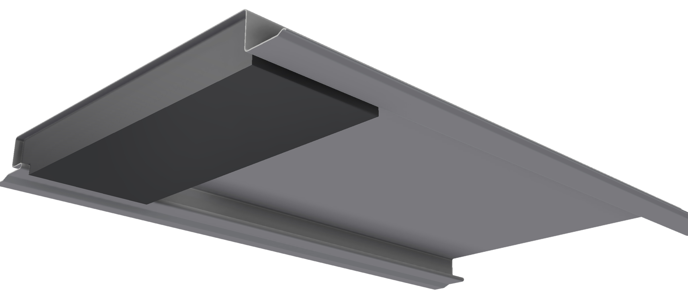
Figure BL ID NC 026
Note:
1. Foam is required for horizontal panels to stop water egress behind the panels.
2. Foam to be 80mm wide x 30mm high x 1.2m long closed cell foam cut to size on site.
BL INS NC 001
Note:
Image displayed using Shadowline profile