
Rainfall Capacity
For further information, please refer to sections “Rainfall Intensity” and “Water Carrying Capacity and Rainwater Run-Off”.
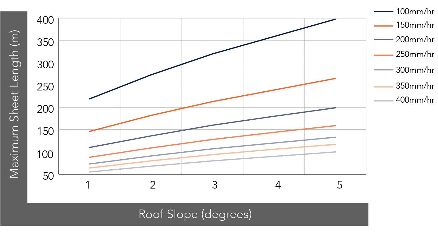
Figure SL RC NC 001
Maximum Roof Length (m)
| Roof Slope (degrees) | Rainfall Capacity (mm/hr) | ||||||
| 100 | 150 | 200 | 250 | 300 | 350 | 400 | |
| 1 | 219 | 146 | 110 | 88 | 73 | 64 | 55 |
| 2 | 273 | 182 | 136 | 109 | 91 | 80 | 68 |
| 3 | 320 | 213 | 160 | 128 | 107 | 94 | 80 |
| 4 | 359 | 239 | 180 | 144 | 120 | 106 | 90 |
| 5 | 398 | 265 | 199 | 159 | 133 | 117 | 100 |
Note:
- Minimum recommended slope is 1°. Sheet lengths greater than 24m are not recommended due to thermal expansion and contraction.

Figure SL BP 001
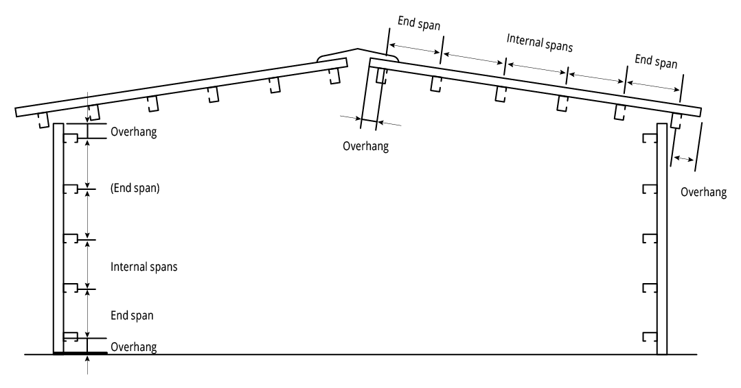
Figure SL NC 001 End Spans, Internal Spans and Overhangs

Figure SL PF 001
Figure SL NC 001 End Spans, Internal Spans and Overhangs
Installation Guidelines: Button Punched (Concealed Fixed)
Step 1
Place first sheet down with the correct length into the gutter. Using the rib closing tool squash the female rib and place a top fixing clip over and fix to the purlin.
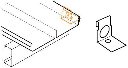
Figure SL IG NC 001
Step 2
Using the rib closing tool squeeze the male rib of the first sheet. Place top fixing clip over each squashed male rib and fix to purlin. This needs to be done to prevent the sheet from lifting in the wind before the barges are fitted. The use of string lines will assist in ensuring sheets are installed straight.
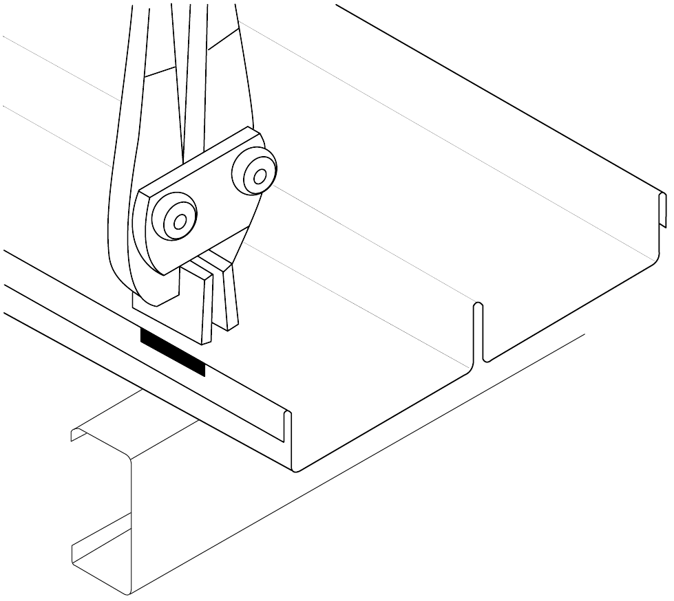
Figure SL IG NC 002
Step 3
Make a small non-permanent mark in the pan to enable you to locate the clips in the latter locking operation with the button punch.
Step 4
Position the female rib of the next sheet over the male rib and clips ensuring that it is fully engaged. Fully engage the sheet with the clips using foot pressure on the ribs over each clip. You can do this by walking along the full length of the sheet with one foot in the tray next to the overlapping rib and the other foot applying pressure to the top of the interlocking ribs at regular intervals.
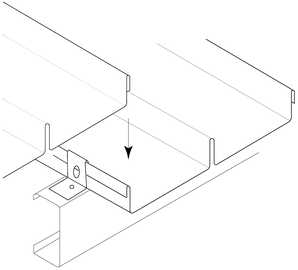
Figure SL IG NC 003
Step 5
Repeat steps 3 to 5.
Step 6
All lapped ribs must be locked along their length, by button punching at the clips, and if necessary between the clips (typically at 900mm centre to centre). Punching to a string line guide stretched across the sheeting is recommended as random punching marks the appearance of the finished work.
Step 7
You must button punch through the hole in each top fixing clip, you can locate the clip with the non-permanent mark made previously. When operating the punching tool, stand on the pan of the overlapping sheet to ensure that the sheets are fully engaged.
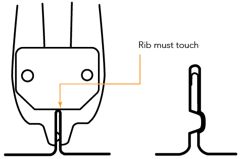
Figure SL IG NC 004
Ends of Sheets
Wind can drive water uphill under the flashings or cappings. Also, at the low end of a roof, wind or capillary action can cause water to run back up the underside of the sheeting. To minimise these problems, turn the pans up at the top of sheets, and turn them down at the bottom. A tool is available for these jobs (ref. Figure SL IG NC 005).
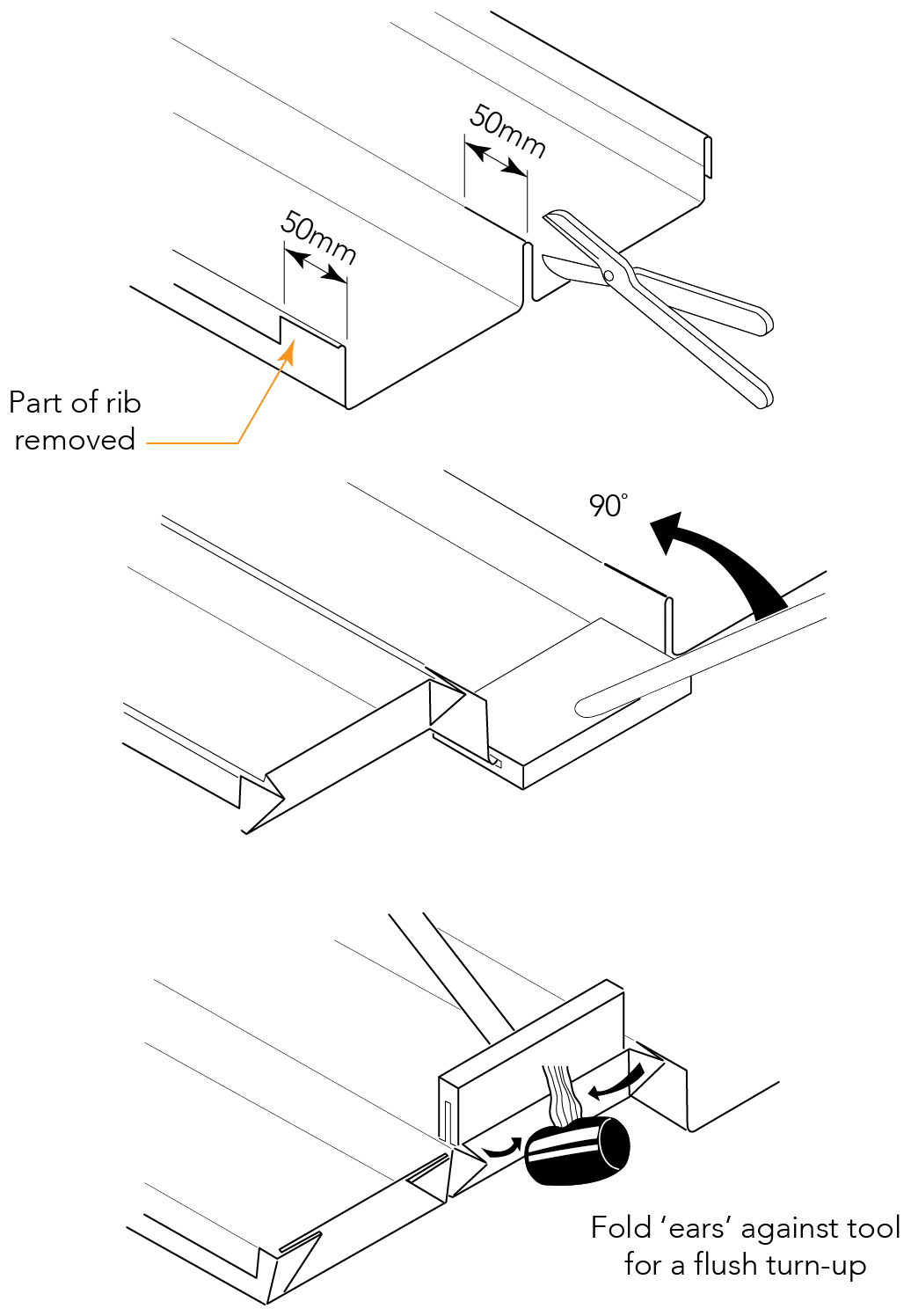
Figure SL IG NC 005
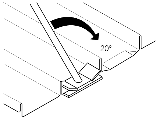
Figure SL IG NC 006
Figure SL IG NC 007
Figure SL IG NC 008
Figure SL IG NC 009
Figure SL IG NC 010
Figure SL IG NC 011
Figure SL IG NC 012
Figure SL IG NC 013
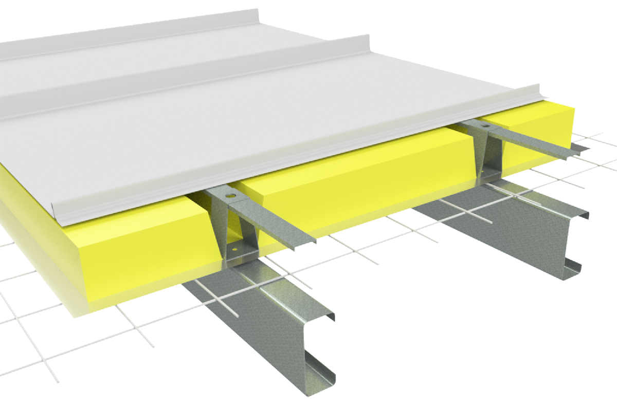
Insulation
Care needs to be taken when installing insulation with Shadowline® roof sheeting. When insulation thicknesses up to 50mm are installed the screws may need to be increased depending on the thickness and density of the insulation. When the screw is properly tightened into metal there should be a minimum of three (3) threads protruding past the support being fixed in to. For timber, the screw must have a minimum embedment of 25mm into timber.
When insulation is required in conjunction with Finesse® profiles, Fielders® recommend the use of a thermal spacer to help maintain Rw values as well as minimising any bulging in the profile caused by the insulation.
Insulation blankets and batts can cause wide flat pan cladding to bow out between the supports, between fasteners along the support, or bow the pans. For insulation blankets and batts as well as more dense glass wool and rock wool, and thicker insulation, spacers are recommended.