Scope of the Roofing and Walling Manual
The information, data and diagrams presented on this site are intended as a guide in the design and installation of Fielders® roofing and wall cladding products as well as the associated fasteners and accessories. We refer to each categorised section as a 'manual' and each manual assists in the easy specification of Fielders® products for all personnel involved in cladding projects from architects and engineers to contractors and builders on site. By following the guidelines in this portal, a cost effective, efficient and aesthetically pleasing roof or wall cladding can be achieved.
The data and information presented in this portal deals specifically with the broad range of products available from Fielders® and must not be used on competitors’ products.
Access the Roofing and Walling manual using the icons below or navigate via the top menu.


Product Selection
Fielders® provide a wide range of cladding profiles for you to select from. When choosing a profile or product, the designer or specifier needs to consider the following design factors:
Roof Cladding
Roof Length and Pitch
The length of your roof from ridge to gutter and the pitch of your roof have a direct effect on its capacity to effectively shed rainwater. Steeply pitched roofs shed water more quickly and hence longer lengths can be used. The length of the roof also affects the sizing of gutters and downpipes. Care must be taken in the design of the supporting structure if using very low pitched roofs to prevent possible ponding of rainwater. Use a minimum roof slope of 1° (or 1 in 60). On very long roofs, thermal expansion and contraction can cause a problem if the incorrect sheeting profile and fastening system are specified and thus, step joints may be required (see section “Thermal Expansion and Contraction of Steel Sheeting” for more details). Fielders® recommend the use of long length concealed fix sheets rolled on site to avoid step joints (refer to section “Long Length Roofing Solutions” and "Comparative Analysis: Concealed Fix vs Screw Fix").
Loads
Loads that need to be considered when designing cladding include dead, live, wind and snow loads. Dead loads allow for the self weight of the cladding, whereas live loads allow for stacked materials or maintenance equipment that may be used on the roof (in accordance with AS 1170.1:2002). Wind loading is often the most critical load case for cladding design, particularly for uplift on the cladding. In snow regions, the effect of snow loading on the cladding can be very severe. Refer to the product specific load capacity tables presented in this manual for more information. You can also learn more about wind loads in our profile selection guide.
Shape of Roof
Curved or wave-form roofs can be formed by either pre-curving the cladding for smaller radius curves or by spring fixing/curving for large radius curves. Pre-curved corrugated sheeting can be curved to radius as tight as 450mm whereas spring curved roofing generally starts at a radius of 9m depending upon the profile and thickness of the cladding. Refer to section “Curving of Steel Decks” for more information on the design of curved roofs.

Wall Cladding
General
Wind loading is the major design loading on wall cladding and, in terms of the roof design, affects the spacing of supports. Similarly, thermal expansion and contraction can cause problems on very long lengths of walls, meaning step joints may be required. Other main design considerations relate to the aesthetics of the building, including fastening details, flashing details, trimming and surface texture.
You can check the wind loads in your region in our profile selection guide.
Materials and Finishes
Fielders® metal roof and wall cladding products are generally manufactured from G550 (550MPa tensile strength) steel sheeting and are available in both ZINCALUME® steel and COLORBOND® steel finishes.
For pre-curved sheeting, grade G300 (300MPa tensile strength) steel sheeting is used. ZINCALUME® steel cladding products comply with the requirements of AS 1397:2011 and AS 2728:2013. The base steel comes with a standard AM100 ZINCALUME® steel base for COLORBOND® steel or AM150 ZINCALUME® steel base for COLORBOND® Ultra pre-painted finish in compliance with AS 2728:2013.
COLORBOND® steel is suitable for general exterior roofing and walling applications and is the most widely used pre- painted finish. COLORBOND® Ultra pre-painted finish is suitable for use in coastal and industrial settings, while SuperDura™ Stainless should be used in severe marine environments.
Galvanised finishes are available for S-Rib Corrugated and Spanform® cladding with a choice of either a Z450 coating (450g/m2 of zinc) or the heavier duty Heritage Galvanised finish of Z600 (600g/m2 of zinc). All materials comply with the requirements of AS 1397:2011.
Roof and wall cladding is generally available in 3 gauges, specified as the Base Metal Thickness (BMT) and measured in millimetres (mm). 0.42mm BMT is the most economical and is generally applied in domestic situations, while the 0.48mm BMT is a slightly heavier gauge that is more suited to commercial construction. The third most common gauge is 0.60mm BMT and is used for pre-curved sheeting and for particular applications where longer spans or greater strength is required.
The following product selection guide includes details of BMT for each of the Fielders® cladding profiles.
Testing has been carried out on Fielders® roof and wall cladding in accordance with AS 1562.1:2018. “Design and Installation of Sheet Roof and Wall Cladding: Metal” and AS 4040.1:1992 “Methods of Testing Sheet Roof and Wall Cladding: Resistance to Concentrated Loads”. Loads were determined in accordance with the following: AS 1170.1:2002 “Dead and Live Loads and Load Combinations”; AS 1170.2:2011 “Wind Loads”.
Your Problems – Fielders® Solutions
Custom Design Assistance
Architectural imagination has long been constrained by manufacturing capabilities. Steel as a building material can be rigid and restrict the creative boundaries of Australia’s best Building Designers. Fielders® are prepared to go the extra mile and work with you to achieve solutions that ‘push the limits’ and extend the manufacturing capability of steel roll formers and fabricators.
Fielders® have historically provided solutions to complex problems using state of the art manufacturing methods and machinery through customising products and finishes to suit your particular requirements. Their fleet of mobile mills bears testament in that nationally Fielders® were the first manufacturer to ‘go to any lengths’ and roll roofing sheets in excess of 100m thus avoiding step joints on buildings of any size.
Specific Challenges
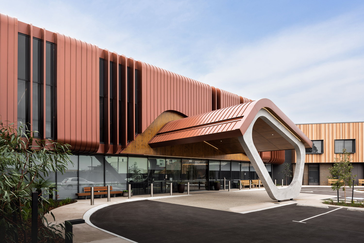
When it comes to innovating a specific solution such as involving the use of smooth curving or crank curving technology Fielders® are at the cutting edge of these processes and will assist during the design process. The Opal Aged Care Facility in Perth is a prime example of a stylish concealed fix smooth curved roof that Fielders® uniquely was able to manufacture.
Different materials, some of which are exclusive to Fielders® provide opportunities to offer unique solutions in locations that present challenges namely marine and chemically corrosive environments.
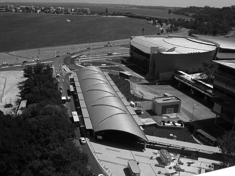
Completed in early 2015, Netball Central Sydney is the latest addition to Sydney Olympic Park's portfolio of 47 world-class sporting and recreational facilities. Fielders ARAMAX® was selected due to the Material's expressive V-shaped aesthetic which worked well with the main structure element of Laminated Veneer Lumber (LVL). The profile's capability to deliver an integrated roofing and ceiling solution, along with long spanning capabilities of over 140 metres, made it the preferred product for the facility.