What is Condensation?
When a surface temperature falls below the dew point of its surrounding air, condensation in the form of water vapour from the humid air will take place on the colder surface. In order to avoid condensation, the surface temperature must be increased and/or the moisture in the surrounding air must be reduced.
Condensation within a building can form as visible surface condensation or can form within the building fabric or layers, referred to as interstitial condensation. Generally small quantities of condensation in a building are tolerable provided it can dry. However, if the environment remains wet or humid for a substantial period of time materials may degrade and mould growth may occur that can have an effect to the health of the occupants in the building.
Increasing levels of energy efficiency provisions in buildings has resulted in greater levels of insulation and buildings being built to be more air tight. Consequently this has led to potential for increased humidity in living spaces and greater risk of problematic condensation.
It is important to note that the new provisions are seeking to minimise the health impact through the management of condensation. It does not look at eradication of condensation as it acknowledges that dealing with condensation in buildings is a complex matter and is as much about how the building is used, as it is about how it is built.
This is reflected in the NCC 2019 Performance Requirement which states:
At P2.4.7 - Condensation and water vapour management - risks associated with water vapour and condensation must be managed to minimise their impact on the health of occupants.
Effect of Condensation (Moisture) in Buildings
In extreme circumstances, it has been documented that moisture in buildings can be associated with a range of adverse health and wellness issues including upper respiratory (nasal and throat) symptoms, coughs, wheezing and asthma symptoms in sensitised persons with asthma. More typically, moisture can cause damage to building materials and components.
For example:
- Prolonged damp conditions can lead to the colonisation of building materials and HVAC systems by moulds, bacteria, wood-decaying moulds and insect pests (e.g. termites and carpenter ants).
- Chemical reactions with building materials and components can cause, for example, structural fasteners, wiring, metal roofing and conditioning coils to corrode and flooring or roofing adhesives to fail.
- Water-soluble building materials (e.g. gypsum board) can return to solution.
- Wooden materials can warp, swell or rot.
- Brick or concrete can be damaged during freeze-thaw cycles and by sub-surface salt deposition.
- Paints and varnishes can be damaged.
- The insulating value (R-value) of thermal insulation can be reduced.
Main Causes of Condensation in Roof Spaces
There are two main causes of condensation in roof cavities;
- High levels of internal water vapour passing into roof spaces through the ceiling or through exhaust fans which are not externally ducted. This is a particular problem in areas of the home where moisture is generated such as laundries, kitchens and bathrooms.
- Insufficient ability for the roof space to dry due to lack of ventilation to remove unwanted water vapour. Once high levels of moisture exist in a roof space the consequence of poor installation, inappropriate materials and or poor construction details further increase issues associated with condensation.
Key Ways to Minimise Condensation in Roof Spaces
- Extraction systems which duct moist air outside the building.
- Maintaining the natural ventilation of the roof space by ensuring insulation and membranes do not block ventilation paths.
- Installing supplementary ventilation as required.
- Providing roof level insulation, such as blanket and foil, particularly in cooler climates.
Ventilation of Roof Spaces
Amendments have been made to the ventilation requirements in NCC 2019. Clause F6.4 (NCC Volume One) and 3.8.7.4 (NCC Volume Two) outline the minimum requirements of an adequately ventilated roof space. These amendments remove ambiguity around what constitutes an adequately ventilated roof space, providing detailed information regarding
- the amount of ventilation required and
- their locations.
Where an exhaust system covered by NCC clauses F6.4 or 3.8.7.3 discharges into a roof space, the roof space must be ventilated to outdoor air through evenly distributed openings. The total area of the openings required for ventilation will vary depending on the pitch of the roof and the ceiling area of the roof space being ventilated.
NCC 2019 Clause F6.4 - Ventilation Requirements for Roof Spaces
| Installed pitch | Relative Ceiling Area | Ventilation at Ridge | Examples |
| Greater than 22° | 1/300 | 30% | Ceiling area: 300m2 Ventilation required: 1m2 Ventilation at ridge: 0.3m2 |
| Less than 22° | 1/150 | 30% | Ceiling area: 300m2 Ventilation required: 2m2 Ventilation at ridge: 0.6m2 |
Roof Ventilations Systems
There are several rooftop ventilations systems available that can be used to meet the requirements of NCC 2019. These include:
- Turbine style ventilators – these are also known as ‘whirlybirds’ and are a semi-mechanical vent comprising a cylindrical dome with fins that spin in the wind creating a vacuum, drawing out air from the roof cavity. Various brand names are readily available and supplied by Fielders.
- 'Ridge Vent' systems – ridge vents have been widely used throughout Europe for many years and comprise an integrated addition under the ridge cap that utilises natural upward air flow facilitated by air intake via soffit vents that draws air through the roof cavity an out the (slightly) raised ridge. VENT-A-ROOF® is a leading example of this technology and is available from Fielders.
- Roof fan systems - a wide variety of solar and mains powered ventilation fans systems are available.
Condensation Management Detailing Examples for Fielders Claddings
Increasing levels of energy efficiency provisions in buildings has resulted in greater levels of insulation and buildings being built to be more airtight. Consequently, this has led to potential for increased humidity in living spaces and greater risk of problematic condensation.
The following ‘moisture management’ diagrams outline typical passive ventilation and moisture paths for metal cladding systems to best control building cavity moisture. The resulting specific construction details are based on these moisture management principles.
All materials and products used should be fit for purpose including suitable durability, compatibility and account for movement when exposed to temperature, moisture and corrosivity of the installed micro-environment.
For specific information on using any product and for details outside of the following, such as for low pitch and bushfire or marine requirements, refer to Fielders for specialist advice.
The two key principles for moisture management for roofs and walls are:
- Keep moisture out. This involves keeping the rain out and controlling internal moisture.
- Allow moisture that enters building cavities to escape. Moisture will get in, and when it does it must be able to escape without consequential damage.
Ensuring a roof or external wall is designed to both keep moisture out and provide for escape of any moisture that enters, is key to reducing moisture related issues. Installing your metal cladding in accordance with these typical construction details will maximise the lifespan of the cladding and building.
Minimum Gaps for Ventilation and Drainage
| Unobstructed Ventilation at eave | Unobstructed Ventilation at ridge | ||
| Roof cavities where no exhaust fan discharges into the roof cavity (not receiving exhaust) | Roof pitches greater than 15° with truss spans less than or equal to 10m | 10,000mm²/lm | 5,000mm²/lm |
| Roof pitches 15° or less or single pitched roofs or truss spans greater than 10m | 25,000mm²/lm | 5,000mm²/lm | |
| Walling | Unobstructed ventilation area of a minimum 5,000mm²/lm of wall run at both the top and bottom of the wall | ||
For roof cavities where an exhaust fan discharges into it (receiving exhaust) NCC 2019 provision apply as per Table F CM NCC2019F6.4.
NCC 2019 Clause F6.4 - Ventilation Requirements for Roof Spaces
| Installed pitch | Relative Ceiling Area | Ventilation at Ridge | Examples |
| Greater than 22° | 1/300 | 30% | Ceiling area: 300m2 Ventilation required: 1m2 Ventilation at ridge: 0.3m2 |
| Less than 22° | 1/150 | 30% | Ceiling area: 300m2 Ventilation required: 2m2 Ventilation at ridge: 0.6m2 |
Steps to Develop Project Based Moisture Management Solutions
Step 1: Determine the application climate zones as per the National Construction Code (NCC).
The NCC outline 8 climate zones for Australia as follows;
| Climate Zone # | Climate Zone Characteristics |
| Zone 1 | high humidity summer, warm winter |
| Zone 2 | warm humid summer, mild winter |
| Zone 3 | hot dry summer, warm winter |
| Zone 4 | hot dry summer, cool winter |
| Zone 5 | warm temperate |
| Zone 6 | mild temperate |
| Zone 7 | cool temperate |
| Zone 8 | alpine |
The applicable geographic regions are outlined below at Figure F CM CZ 001 which is available here. The details provided are generally applicable for Climate Zones 1-6. For Climate Zones 7 and 8 i.e. Alpine specialist advise should be sought.
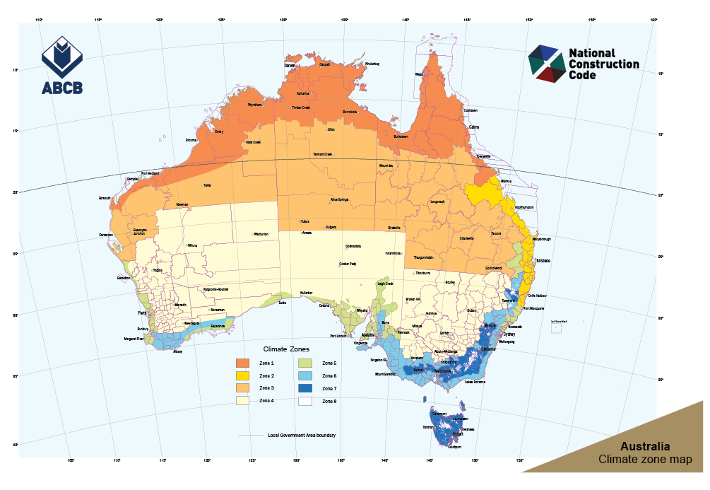
Figure F CM CZ 001
Step 2: Determine if the cladding to be used is supported or unsupported.
Supported claddings require a rigid continuous support such as plywood or similar. Unsupported cladding free span between batten or purlin supports. Most Fielders cladding profiles are unsupported, with the exceptions being;
- Grandeur® over 325mm wide
- Prominence™ over 265mm wide
- Cadence® over 265mm wide
- Neo-Roman®
Step 3: Determine if the cladding to be used is open or closed.
Open profile claddings are those with open ribs that will allow airflow. Examples of these profiles include:
- S-Rib™
- TL-5™
- Spanform™
- KingKlip®
Closed profiles claddings those with closed ribs that do not allow easy airflow. Examples of these profiles include:
- Grandeur®
- Prominence™
- Cadence®
- Shadowline® 305
Step 4: Determine if the cladding is for wall or roof.
Additional considerations include; assessment of Project Bush Fire Attack rating (BAL) to ensure that ventilation solutions comply to BAL requirements assessment of the marine or corrosive influence for the project to ensure that ventilation solutions are sufficiently durable to mitigate aerosol (salt and contaminates) entering building cavities. The control of embers and aerosols migration into buildings can be achieved with the use of mesh covers with typical aperture of max~3mm. When mesh screens are incorporated will require inspection and maintenance to maintain good ventilation.
Step 5: Refer to section on Moisture Management Solution Details.
Refer to the appropriate solution detail for the project.
Trussed Roofs with Self-Supported Metal Cladding
Figures F CM TRSSMC 001 - F CM TRSSMC 003 show insulation options and ventilation and drainage pathways. Trussed roofs comprise of a pitched roof, roof space and flat ceiling. Moisture entering the roof space must be removed by either passive or mechanical ventilation to reduce condensation risk. The following diagrams are relative to passive ventilation paths.
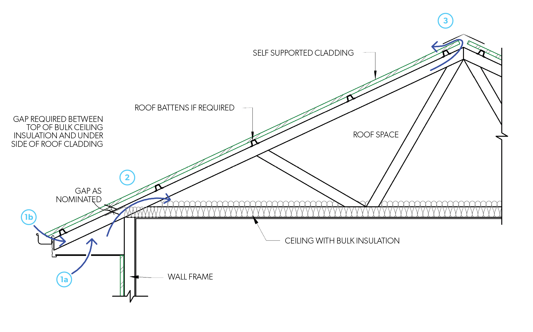
Figure F CM TRSSMC 001 - Trussed roof - No insulation or membrane at roof level
Roof cavity not receiving exhaust:
For roof pitches < 15° passive ventilation must have the min following path:
- 1a or 1b (on opposing eaves); and 2, with both having a min opening area of 25,000mm²/lm.
For roof pitches ≥ 15° or a truss span > 10m, passive ventilation must have the min flow path:
- 1a or 1b (on opposing eaves); and 2, with both having a min opening area of 10,000mm2/m; and 3, with 3 having a min opening area of 5,000mm2/lm.
Where an exhaust system discharges into a roof space NCC 2019 provisions apply as per Table F CM NCC2019F6.4.
NCC 2019 Clause F6.4 - Ventilation Requirements for Roof Spaces
| Installed pitch | Relative Ceiling Area | Ventilation at Ridge | Examples |
| Greater than 22° | 1/300 | 30% | Ceiling area: 300m2 Ventilation required: 1m2 Ventilation at ridge: 0.3m2 |
| Less than 22° | 1/150 | 30% | Ceiling area: 300m2 Ventilation required: 2m2 Ventilation at ridge: 0.6m2 |
Passive vents must prevent water penetration, animals and limit insects from entering the roof space. When mechanical ventilation is used, it must be substituted for and not used in combination with passive venting at the ridge as this may short circuit the eave to ridge ventilation creating stagnant areas within the roof space. Mechanical vents are best used in combination with passive eave or low-level vents to create air exchange throughout the roof space.
Impermeable membranes limit internal moisture between roof cladding and membrane. Metal roof claddings have a low risk of external water penetration. Consequently, the membrane does not need to act as a drainage plane and may be terminated prior to the gutter. Terminating the membrane can allow open profiles to provide similar ventilation to 10,000mm²/m in Australian climates (our S-Rib corrugated profile provides approx. 8,000mm²/m) at eaves and at ridges where flashings have not been scribed.
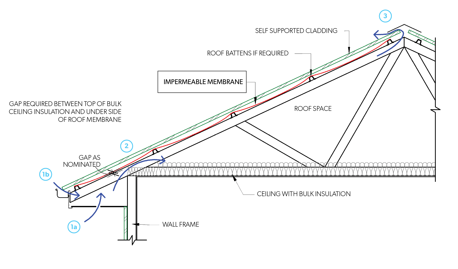
Figure F CM TRSSMC 002 - Trussed roof - Draped impermeable membrane at roof level
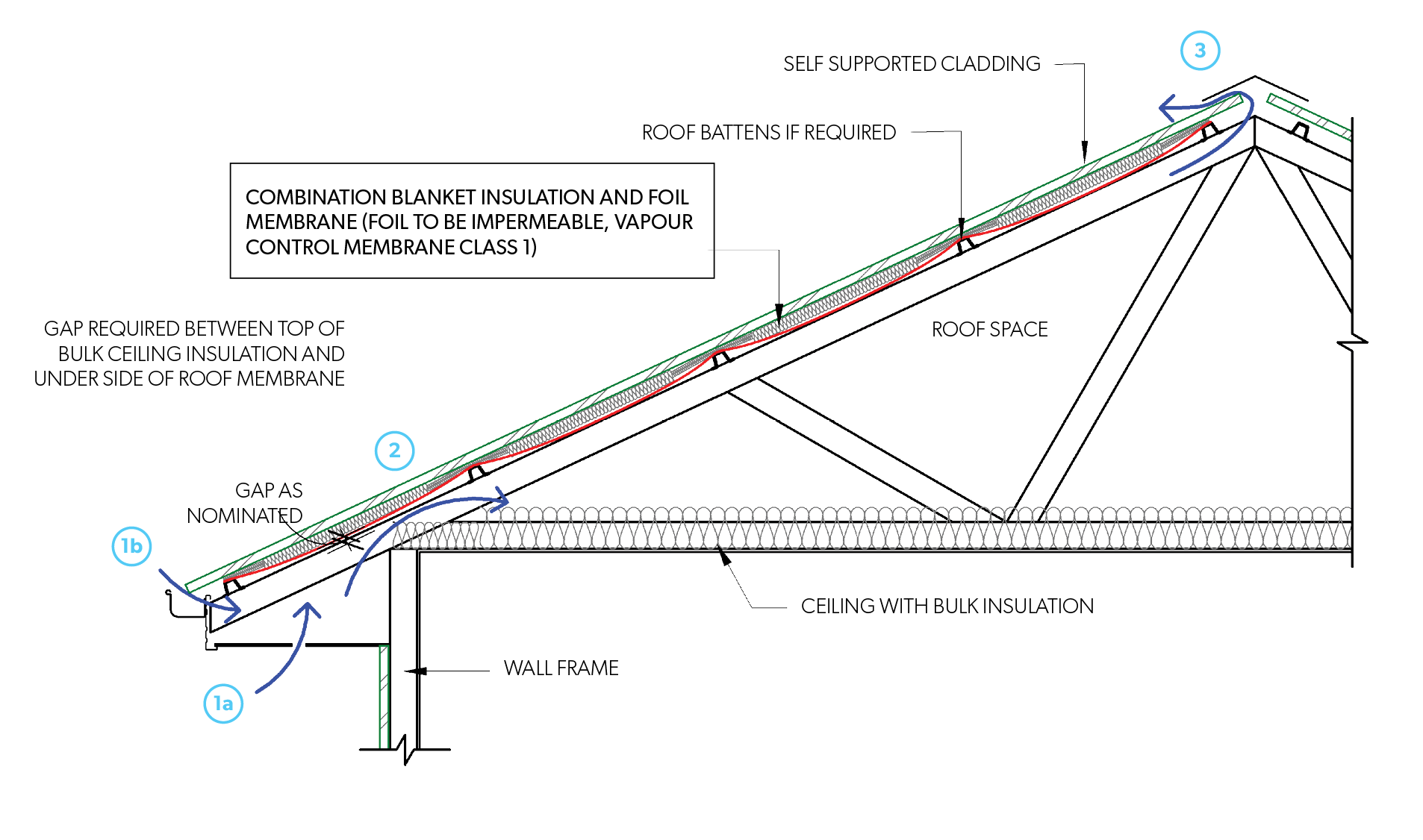
Figure F CM TRSSMC 003 - Trussed roof - Blanket insulation with impermeable foil at roof level
Skillion Roofs with Self-Supported Metal Claddings
Skillion roofs comprise of a pitched roof that incorporates a small cavity with ceiling lining that follows the pitch of the roof. Skillion roofs are more prone to moisture due to a smaller cavity that may be restricted. This coupled with their frequent use at low pitches reduces ventilation and drying potential. Therefore it is recommended that slopes on skillion roofs should be ≥ 3°. For roof pitches < 3° powered roof fan solutions combined with eave ventilation will need to be considered.
Diagrams below are relative to passive ventilation paths. Passive vents must prevent water penetration, animals and limit insects from entering the space.
For all roof pitches ≥3° passive ventilation must have the min following path: 1a or 1b; and 3.
Roof cavities not receiving exhaust
| Min opening area | Unrestricted airflow path (min) | |
| Roof pitches ≥3° | 25,000mm²/lm | 1a or 1b |
| 20,000mm²/lm | Flow path to ridge | |
| 5,000mm²/lm | 3 |
Where an exhaust system discharges into a roof space NCC 2019 provisions apply as per Table F CM NCC2019F6.4.
NCC 2019 Clause F6.4 - Ventilation Requirements for Roof Spaces
| Installed pitch | Relative Ceiling Area | Ventilation at Ridge | Examples |
| Greater than 22° | 1/300 | 30% | Ceiling area: 300m2 Ventilation required: 1m2 Ventilation at ridge: 0.3m2 |
| Less than 22° | 1/150 | 30% | Ceiling area: 300m2 Ventilation required: 2m2 Ventilation at ridge: 0.6m2 |
There is to be a minimum clearance of 20mm at the centre of the underlay of the drape of the impermeable membrane to the insulation.
Impermeable membrane to be Class 1 as per AS/NZS 4200.1. It is typically installed above the supporting battens/purlins and as such should be draped to create a thermal barrier and minimise contact with the cladding above.
Impermeable membranes limit internal moisture between cladding and membrane. Metal roof claddings have a low risk of external water penetration. Consequently, the membrane does not need to act as a drainage plane and may be terminated prior to the gutter.
When mechanical ventilation is used it must be substituted for and not used in combination with passive venting at the ridge as this may short circuit the eave to ridge ventilation creating stagnant areas within the roof space. Mechanical vents are best used in combination with Passive eave or low-level vents to create air exchange throughout the roof space.
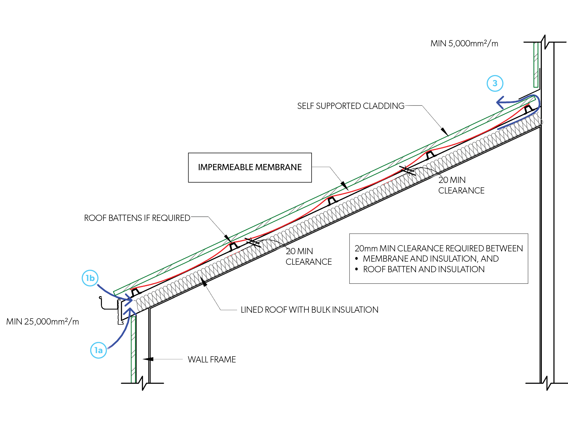
Figure CM SRSSMC 001 - Skillion roof - Draped impermeable membrane
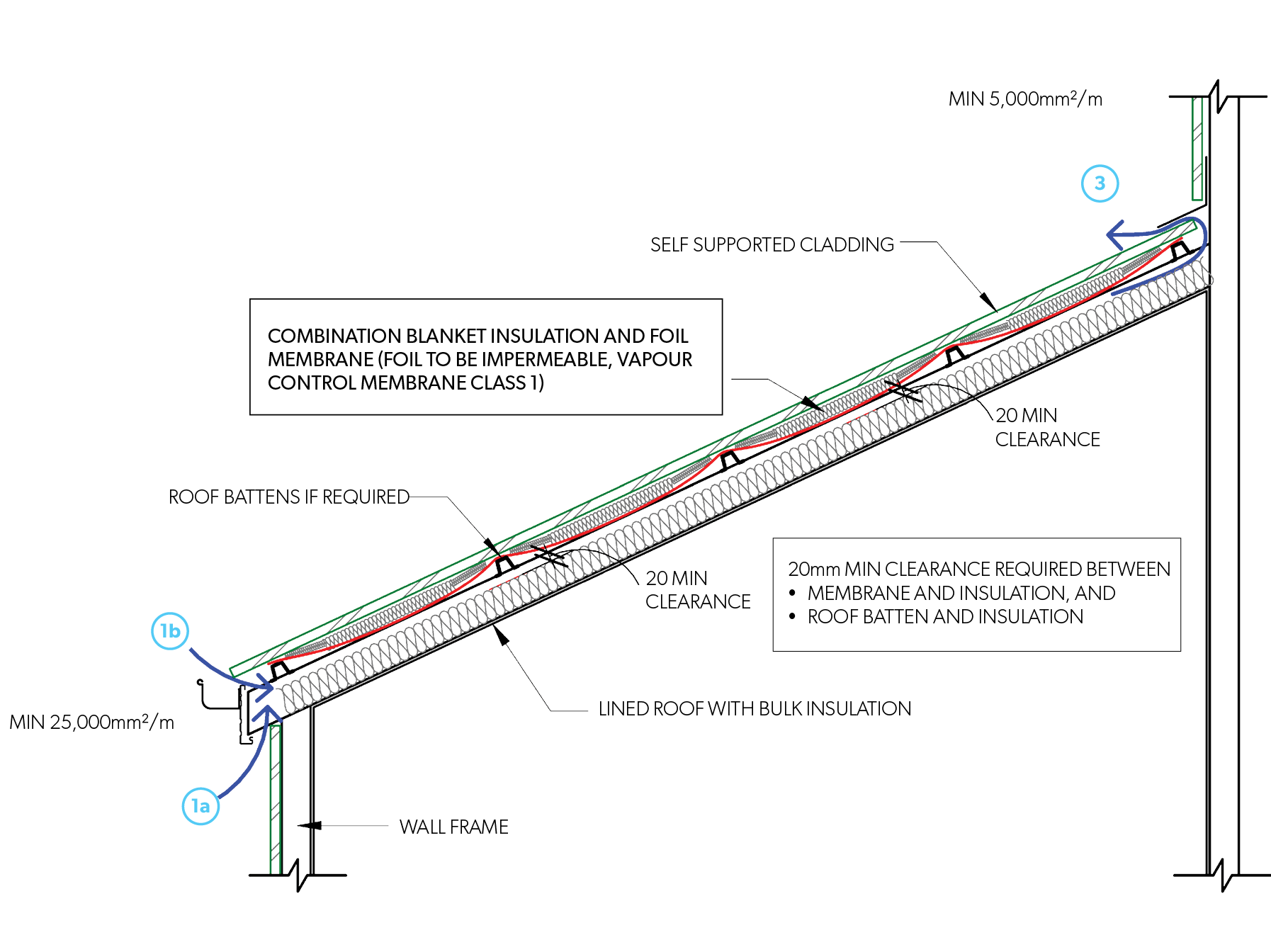
Figure CM SRSSMC 002 - Skillion roof - Blanket insulation with impermeable foil membrane
Trussed Roofs with Supported Metal Claddings
Trussed roofs comprise of a pitched roof, roof space and flat ceiling. For supported claddings the system incorporates a rigid support over the top of trusses/battens to which the cladding is attached. Moisture entering the roof space must be removed by either passive or mechanical ventilation to avoid condensation and consequential damage. The following diagrams are relative to passive ventilation paths.
Passive ventilation should have the following flow path:
- For roof cavities not receiving exhaust;
- For roofs without ridge ventilation:
- 1 on opposing eaves; and 2 with both 1 and 2 having a min opening area of 25,000mm2/lm)/ or
- For roofs with ridge ventilation:
- 1 (on opposing eaves with a min opening area of 10,000mm²/lm); and 2; and 3 (with a min opening area of 5,000mm²/lm).
- For roofs without ridge ventilation:
Where an exhaust system discharges into a roof space NCC 2019 provisions apply as per Table F CM NCC2019F6.4.
NCC 2019 Clause F6.4 - Ventilation Requirements for Roof Spaces
| Installed pitch | Relative Ceiling Area | Ventilation at Ridge | Examples |
| Greater than 22° | 1/300 | 30% | Ceiling area: 300m2 Ventilation required: 1m2 Ventilation at ridge: 0.3m2 |
| Less than 22° | 1/150 | 30% | Ceiling area: 300m2 Ventilation required: 2m2 Ventilation at ridge: 0.6m2 |
Passive vents must prevent water penetration, animals and limit insects from entering the space.
A pliable building membrane is usually installed between the cladding and rigid support as described below as appropriate;
- Impermeable membranes
- Installed as a vapour barrier when installed <10° pitch.
- Membrane shall be self-healing, anti-abrasive and stable at temperatures consistent with metal roof sheet temperatures.
- Permeable membranes
- Permeable membrane shall be class 4 and water barrier to ensure drainage of condensate out of the cavity
- Rigid support to also be permeable to ensure moisture within the roof space can escape via vapour transmitting through to the cladding. Cladding will require venting and draining above the membrane.
- Membrane must have the following properties
- for open profile cladding - membrane Class 4 as per AS/NZS 4200.1, anti-abrasive, water barrier and have absorbency of 150g/m² and drainage capability;
- for all closed profile cladding - membrane Class 4 as per AS/NZS 4200.1, anti-abrasive and is capable of ventilation & drainage (3d mesh types).
- Membrane shall be stable at temperatures consistent with metal roof sheet temperatures.
- Supported roof cladding on permeable membranes is not recommended in climate zones 7 & 8 as defined by NCC 2019.
- Permeable Membranes are not recommended for roof pitches below 10° as they will not facilitate above membrane drainage at low pitches. Impermeable membranes must be used for roof pitches ≤ 10°.
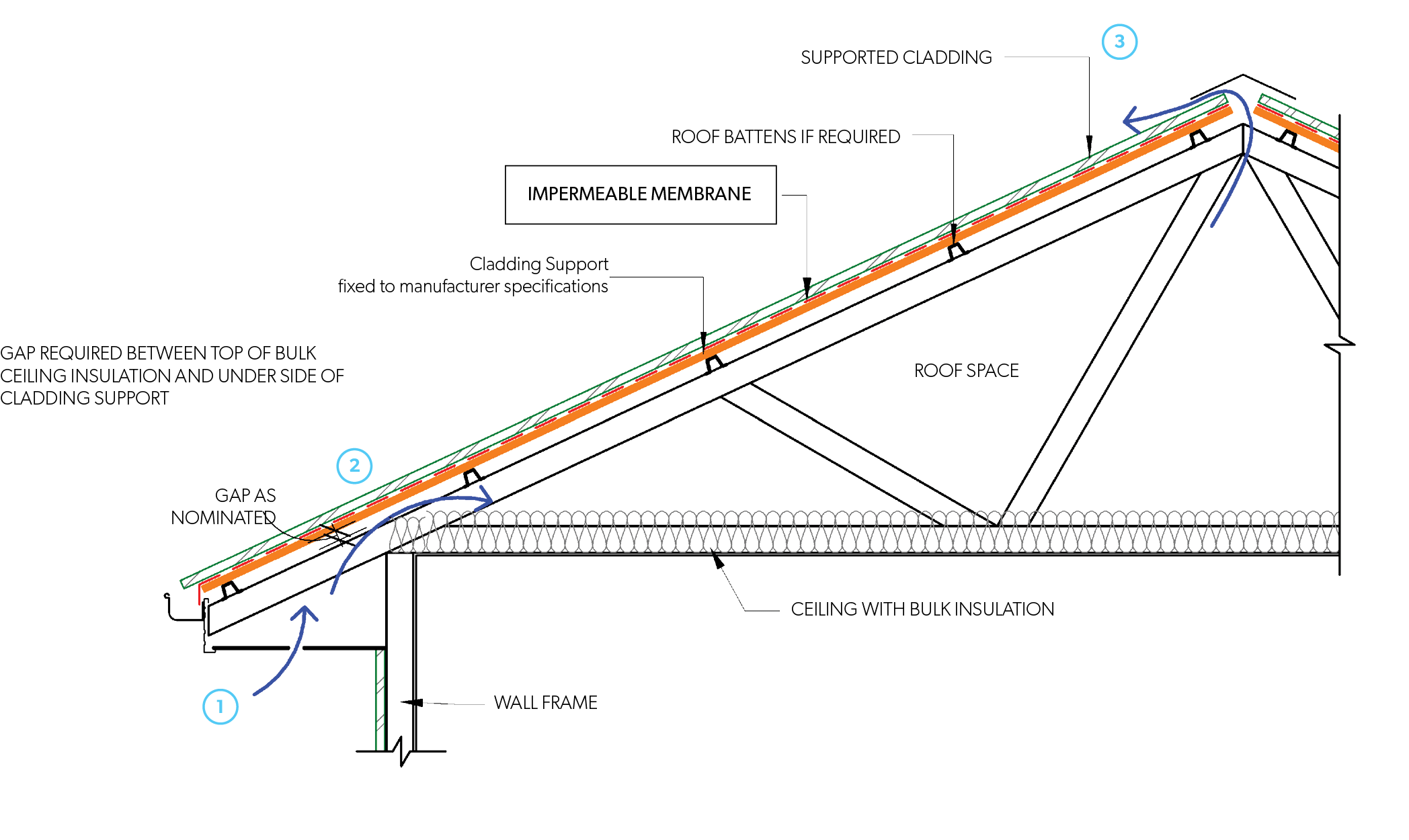
Figure F CM TRSMC 001 - Trussed roof - Impermeable membrane at roof level
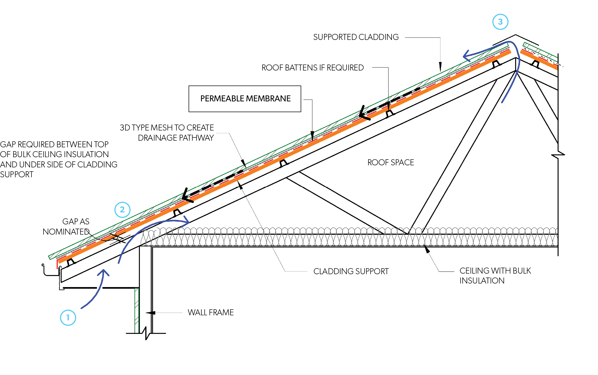
Figure F CM TRSMC 002 - Trussed roof - Permeable membrane at roof level
Skillion Roofs with Supported Metal Claddings
Skillion roofs with supported claddings comprise a pitched roof that incorporates a small cavity with ceiling lining that follows the pitch of the roof. The system further incorporates a rigid support over the top of trusses/battens to which the cladding is attached.
Skillion roofs are more prone to moisture due to a smaller cavity that may be restricted. This coupled with their frequent use at low pitches reduces ventilation and drying potential. Therefore, it is recommended that slopes on skillion roofs should be min 3°. For roof pitches < 3° powered roof fan solutions combined with eave ventilation will need to be considered.
Moisture entering the cavity must be removed by either passive or mechanical ventilation to avoid condensation and consequential damage. The following diagrams are relative to passive ventilation paths. Passive vents must prevent water penetration, animals and limit insects from entering the space.
A membrane is usually installed between the cladding and the cladding support.
For all roof pitches ≥ 3° passive ventilation must have the min following path: 1a or 1b; and 3.
Roof cavities not receiving exhaust
| Min opening area | Unrestricted airflow path (min) | |
| Roof pitches ≥3° | 25,000mm²/lm | 1a or 1b |
| 20,000mm²/lm | Flow path to ridge | |
| 5,000mm²/lm | 3 |
Where an exhaust system discharges into a roof space NCC 2019 provisions apply as per Table F CM NCC2019F6.4.
NCC 2019 Clause F6.4 - Ventilation Requirements for Roof Spaces
| Installed pitch | Relative Ceiling Area | Ventilation at Ridge | Examples |
| Greater than 22° | 1/300 | 30% | Ceiling area: 300m2 Ventilation required: 1m2 Ventilation at ridge: 0.3m2 |
| Less than 22° | 1/150 | 30% | Ceiling area: 300m2 Ventilation required: 2m2 Ventilation at ridge: 0.6m2 |
- Impermeable membrane
- Membrane to be installed as a vapour barrier when installed <10°.
- Membrane to be vapour control Class 1 as per AS/NZS 4200.1, self-healing, anti-abrasive and stable at temperatures consistent with metal roof sheet temperatures.
- Permeable membrane
- Shall be class 4 and water barrier to ensure drainage of condensate out of the cavity
- Rigid support to also be permeable to ensure moisture within the roof space can escape via vapour transmitting through to the cladding. Cladding will require venting and draining above the membrane.
- Membrane must have the following properties:
- for open profile cladding- membrane Class 4 as per AS/NZS 4200.1, anti-abrasive, have absorbency of 150g/m² and drainage capability;
- for all closed profile cladding- membrane Class 4 as per AS/NZS 4200.1, anti-abrasive and is capable of ventilation & drainage (3d mesh types).
- Membrane shall be stable at temperatures consistent with metal roof sheet temperatures.
- Supported roof cladding, on permeable membranes, is not recommended in NCC climate zones 7 & 8.
- Permeable Membranes are not recommended for roof pitches below 10° as they will not facilitate above membrane drainage at low pitches. Impermeable membranes must be used for roof pitches ≤ 10°.
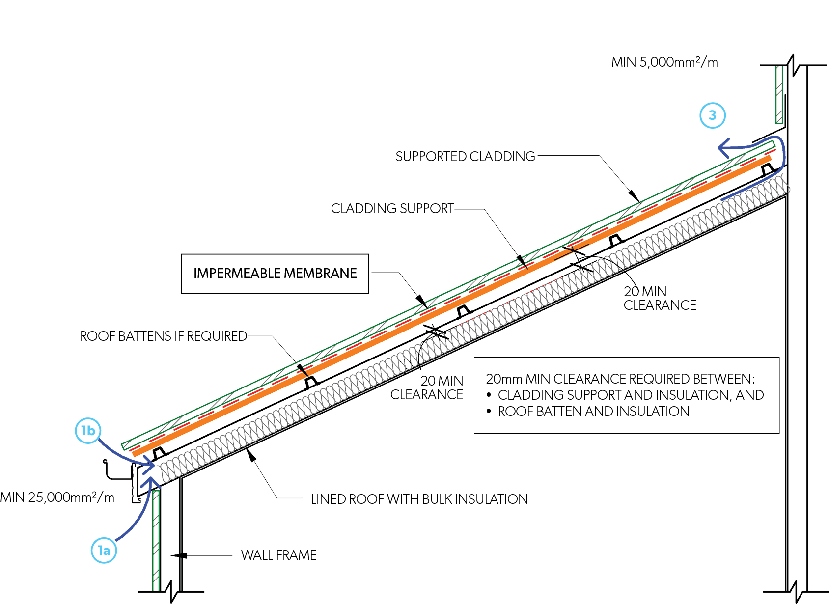
Figure F CM SRSMC 001 - Skillion roof - Impermeable membrane
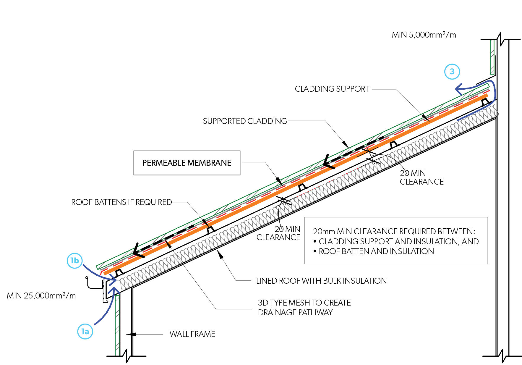
Figure F CM SRSMC 002 - Skillion roof - Permeable membrane
Condensation Control in Walls
When using a pliable building membrane, there are two key points to consider:
- Is a pliable building membrane required?
- Does the pliable building membrane need to be vapour permeable?
NCC 2019 condensation management principles apply to walling as well as roof cavities. NCC 2019 Deemed to Satisfy (DTS) Provisions are outlined in Figure F CM DTS 001 which presents a flow chart of the DTS Provisions for condensation management using pliable building membranes.
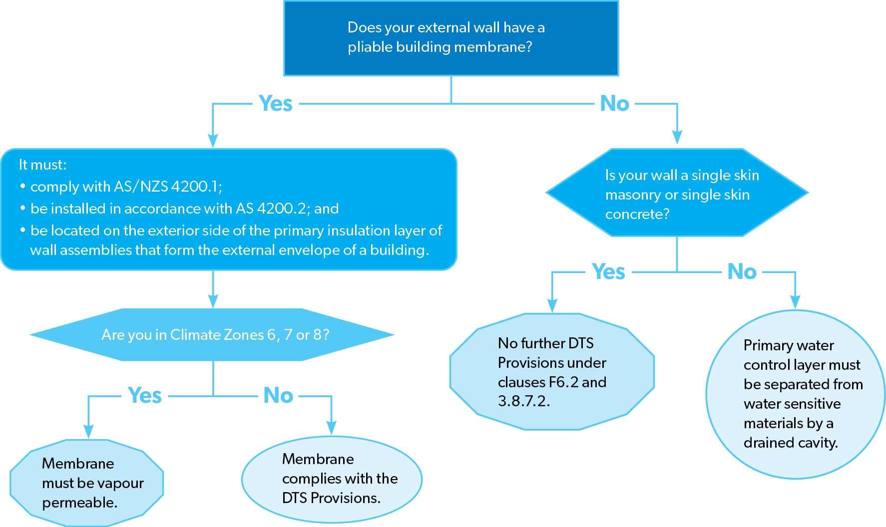
Figure F CM DTS 001 - DTS Provisions for condensation management using pliable building membranes flow chart
Recommended best practice application of pliable membranes in walling
| Climate Zone | Warm Humid | Temperate | Cold | |
| Pliable wall membrane as per AS/NZS 4200.1 | Climate Zone 1 | Climate Zone 2-5 | Climate Zone 6 | Climate Zone 7-8 |
| Impermeable wall membrane | Suitable | Not suitable | ||
| Class 3 permeable wall membrane | Not suitable | Suitable | Not suitable | |
| Class 4 permeable wall membrane | Suitable | |||
A pliable building membrane may be required for different reasons such as weatherproofing purposes, energy efficiency (i.e. part of the total R Value of the envelope) or managing condensation. In some instances, it’s also common practice to install a pliable building membrane where it’s not strictly required. As an example, a builder or designer might include a pliable building membrane as an extra layer of weatherproofing/insulation or to protect water sensitive materials. In this situation, whilst well-intentioned, it might inadvertently create a risk associated with water vapour and condensation.
When thinking about whether a pliable building membrane needs to be vapour permeable or not, how the water vapour moves through the building envelope needs to be considered. A pliable building membrane is often placed on the external side of water sensitive materials. This may prevent water vapour from escaping the building envelope, creating a situation where condensation accumulates on the internal side of the pliable building membrane (where the water sensitive materials are located).
NCC 2019 addresses this issue by requiring that pliable building membranes installed in cooler climate zones i.e. 6, 7 and 8 be vapour permeable membranes regardless of why they have been installed.
Walls with Self-Supported Metal Claddings - Installed Horizontally or Vertically
Internal linings of all wall systems (timber or steel framed) should be tightly sealed to minimise the risk of internally generated moisture moving into the wall. Insulation placed within the wall should be adequately contained so that it will not move, be subject to moisture or restrict ventilation of a cavity.
The membrane outside the frame should be suitable to the applicable climate zone as per Table F CM APMW and be stable at temperatures consistent with metal wall sheet temperatures.
Open mesh, screen or similar with an open area of min 5,000mm²/m may be provided at the bottom and/or top of the profile.
Open profile claddings – Installed Vertically
- Cladding maybe fixed to battens or directly to framing. Direct fixing is suitable as open Profiles provide enough ventilation and drainage. Direct fixed cladding to steel frame requires inclusion of a thermal break between the cladding and the steel framing in accordance with NCC 2019 requirements.
- The profile flashings should not seal the cladding to allow ventilation and drainage from behind the cladding profile.
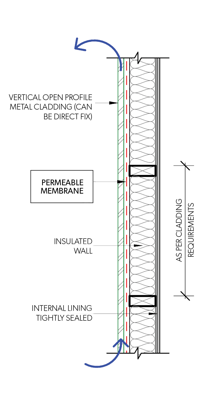
Figure F CM SSMCI 001 - Side Elevation - Open Profile - Vertical Fix
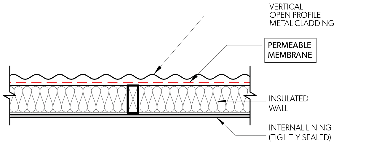
Figure F CM SSMCI 002 - Plan View - Open Profile - Vertical Fix
Open profile claddings - Installed Horizontally
- Fix to vertically install battens to allow suitable ventilation drainage from behind the cladding profile.

Figure F CM SSMCI 003 - Side Elevation - Open Profile - Horizontal Fix
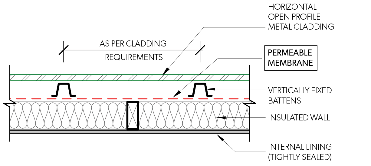
Figure F CM SSMCI 004 - Plan View - Open Profile - Horizontal Fix
Closed profile claddings - Installed Vertically or Horizontally
- Cladding must be fixed to battens to create a drained and ventilated cavity behind the cladding. Batten installation shall be designed to avoid pondage of water. We recommend a packing piece behind every fixing point.
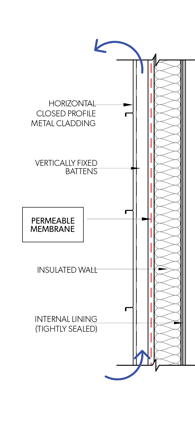
Figure F CM SSMCI 005 - Side Elevation - Closed Profile - Horizontal Fix
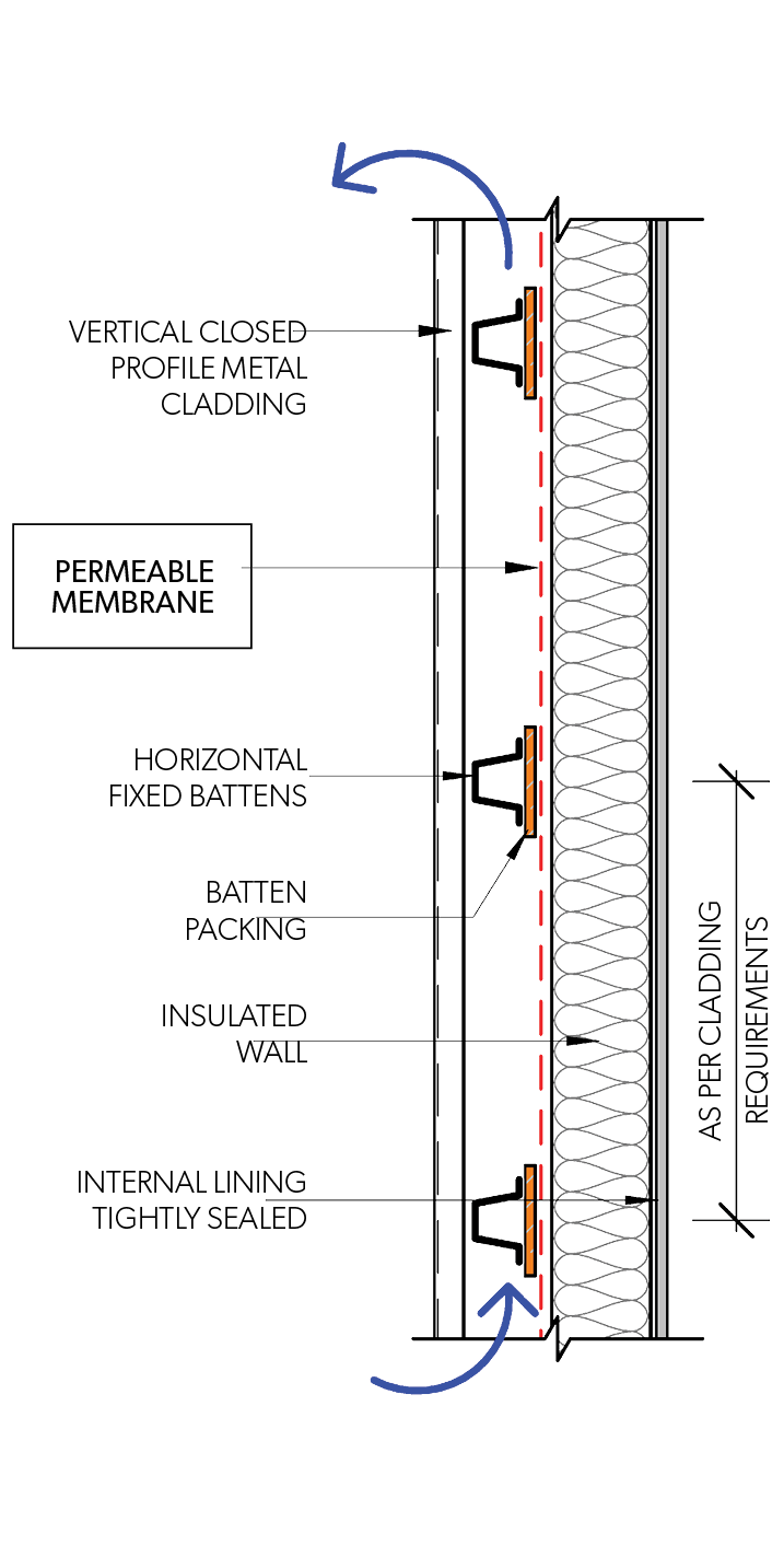
Figure F CM SSMCI 007 - Side Elevation - Closed Profile - Vertical Fix
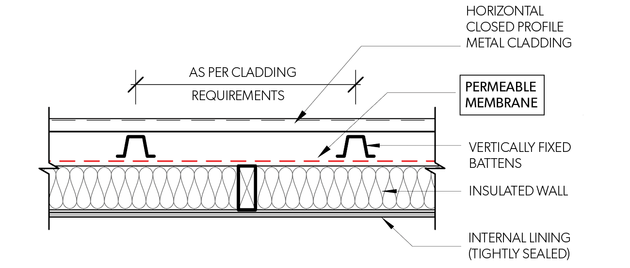
Figure F CM SSMCI 006 - Side Elevation - Closed Profile - Horizontal Fix
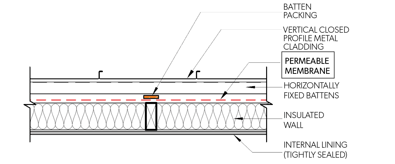
Figure F CM SSMCI 008 - Plan View - Closed Profile - Vertical Fix
Walls with Supported Metal Claddings - Installed Horizontally or Vertically
Information outlined herein assumes that supported metal wall claddings are Closed profiles. (Open profiles are generally self-supporting).
Internal linings of all wall systems (timber or steel framed) should be tightly sealed to minimise the risk of internally generated moisture moving into the wall. Insulation placed within the wall should be adequately contained so that it will not move, be subject to moisture or restrict ventilation of a cavity.
Membranes are to be installed between the cladding and the rigid support. The following considerations are applicable to:
- Impermeable and Permeable membranes
- Impermeable membrane
- Passive ventilation of the cavity behind the rigid support must be provided to remove internal moisture. This is achieved by installing battens behind the rigid support to create a drained and ventilated cavity.
- The batten installation shall be designed to avoid pondage of water.
- Open mesh, screen or similar with an open area of min 5,000mm²/m may be provided at the bottom and/or top of the profile to block pests.
- The impermeable membrane to be vapour control Class 1 as per AS/NZS 4200.1, self-healing, anti-abrasive and stable at temperatures consistent with metal wall sheet temperatures.
- Impermeable membrane
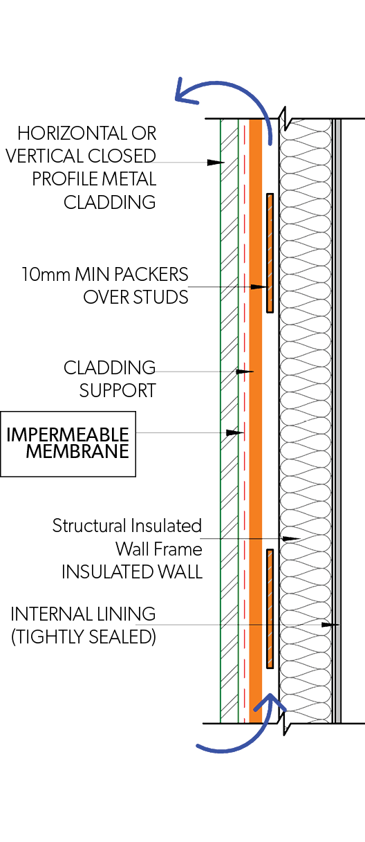
Figure F CM SMCI 001 - Side Elevation - Closed Profile - Horizontal & Vertical Fix
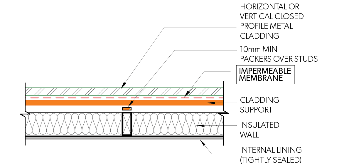
Figure F CM SMCI 002 - Plan View - Closed Profile - Horizontal & Vertical Fix
- Permeable membranes
- The rigid support should also be permeable to ensure moisture within the wall space can escape via vapour transmitting through to the cladding. The cladding must be designed to be vented and draining at the membrane.
- The Permeable membrane must have the following properties:
- Suitable to the applicable climate zone as per table 1, anti-abrasive and is capable of ventilation and drainage (3d mesh types).
- Membrane shall be stable at temperatures consistent with metal sheet temperatures.
- The rigid support may be directly fixed to the frame providing the internal lining is adequately sealed so as to provide an air barrier to the wall cavity. To create this air gap, it is recommended to fix to battens to create a vented and drained cavity as per impermeable membrane.
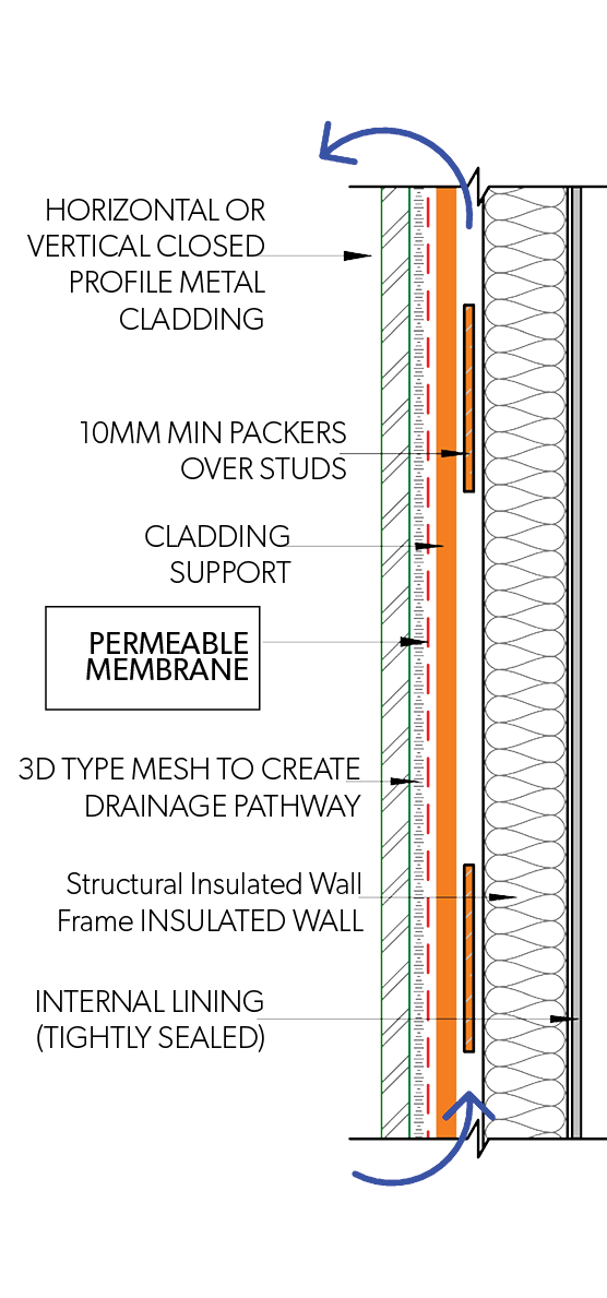
Figure F CM SMCI 003 - Side Elevation - Closed Profile - Horizontal & Vertical Fix
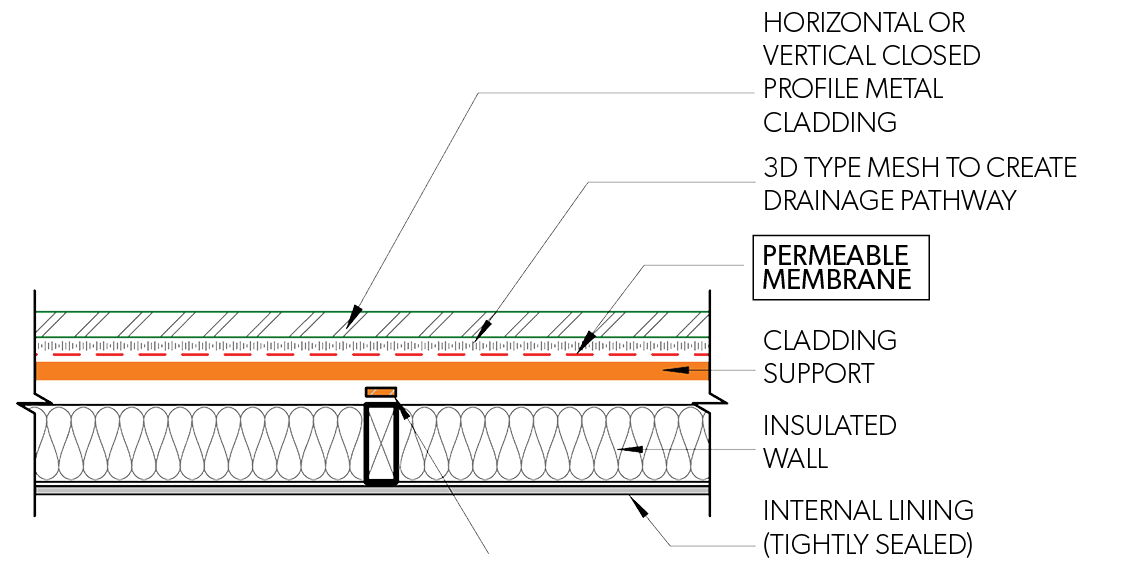
Figure F CM SMCI 004 - Plan View - Closed Profile - Horizontal & Vertical Fix
Walls with Self-Supported Metal Rain Screens or Panelised Claddings - Installed Horizontally or Vertically
Metal rain screen/panelised wall systems require a secondary weather protection layer (membrane) behind to provide both drainage of the rain that penetrates to outer metal skin, and ventilation to dry the cavity behind.
Internal linings of all wall systems (timber or steel framed) should be tightly sealed to minimise the risk of internally generated moisture moving into the wall. Insulation placed within the wall should be adequately contained so that it will not move, be subject to moisture or restrict ventilation of a cavity.
Battens and membrane installation should be designed to avoid pondage of water and protection from capillary action at joints and laps.
- Impermeable membrane
- When impermeable membrane is selected, it must be installed to allow internal moisture to escape and protect internal framing and insulation. As this method is hard to achieve, we recommend the use of permeable membranes only with self-supporting panelised metal cladding.
- Permeable membrane
- Membrane must have the following properties:
- shall be suitable to the applicable climate zone as per Table F CM APMW and anti-abrasive
- have absorbency of 150g/m² and drainage capability
- shall be stable at temperatures consistent with metal cladding temperatures.
- Membrane must have the following properties:
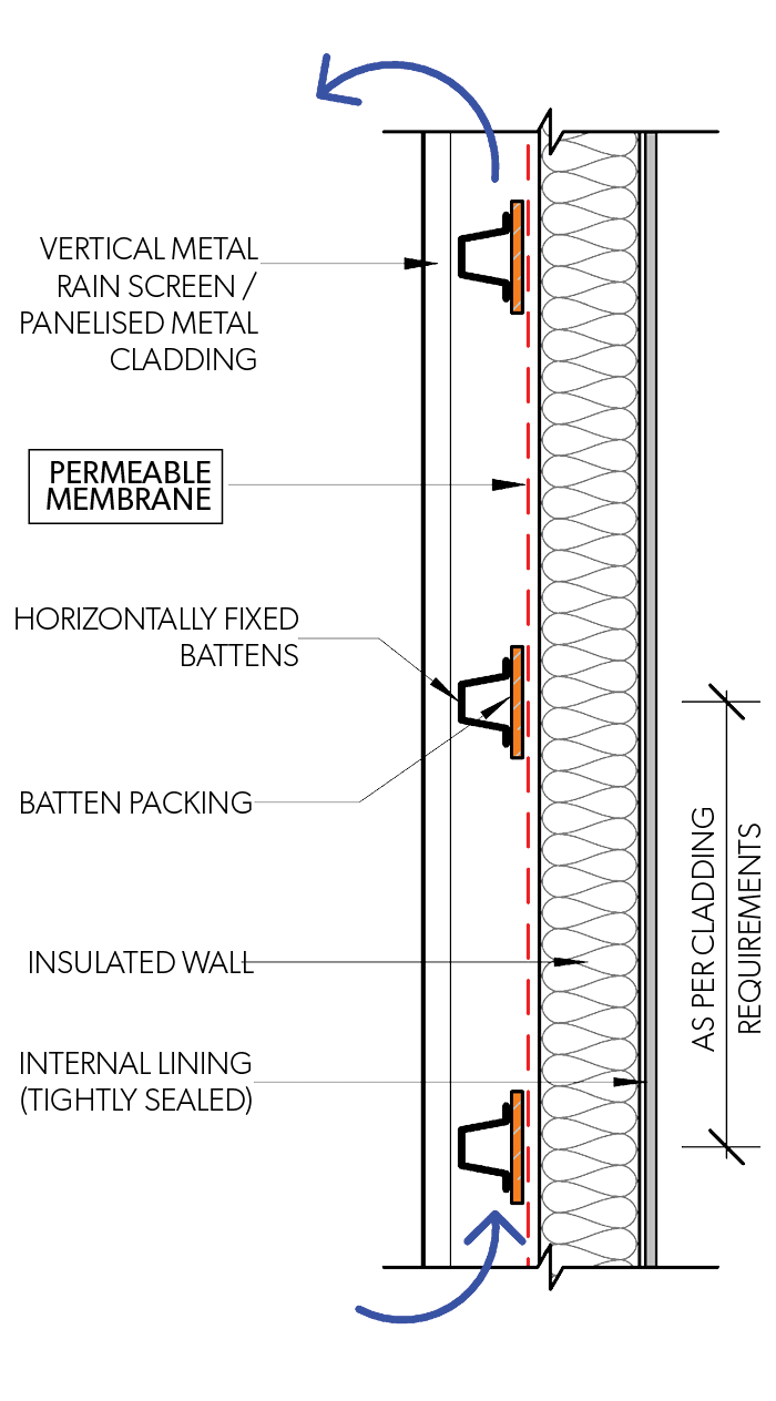
Figure F CM SSMPI 001 - Side Elevation - Panelised Profile - Vertical Fix
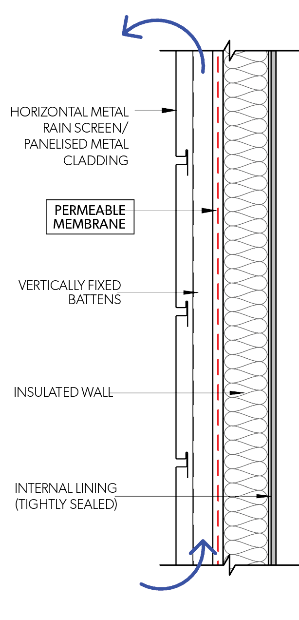
Figure F CM SSMPI 003 - Side Elevation - Panelised Profile - Horizontal Fix
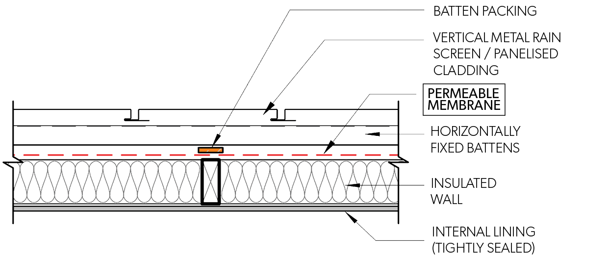
Figure F CM SSMPI 002 - Plan View - Panelised Profile - Vertical Fix
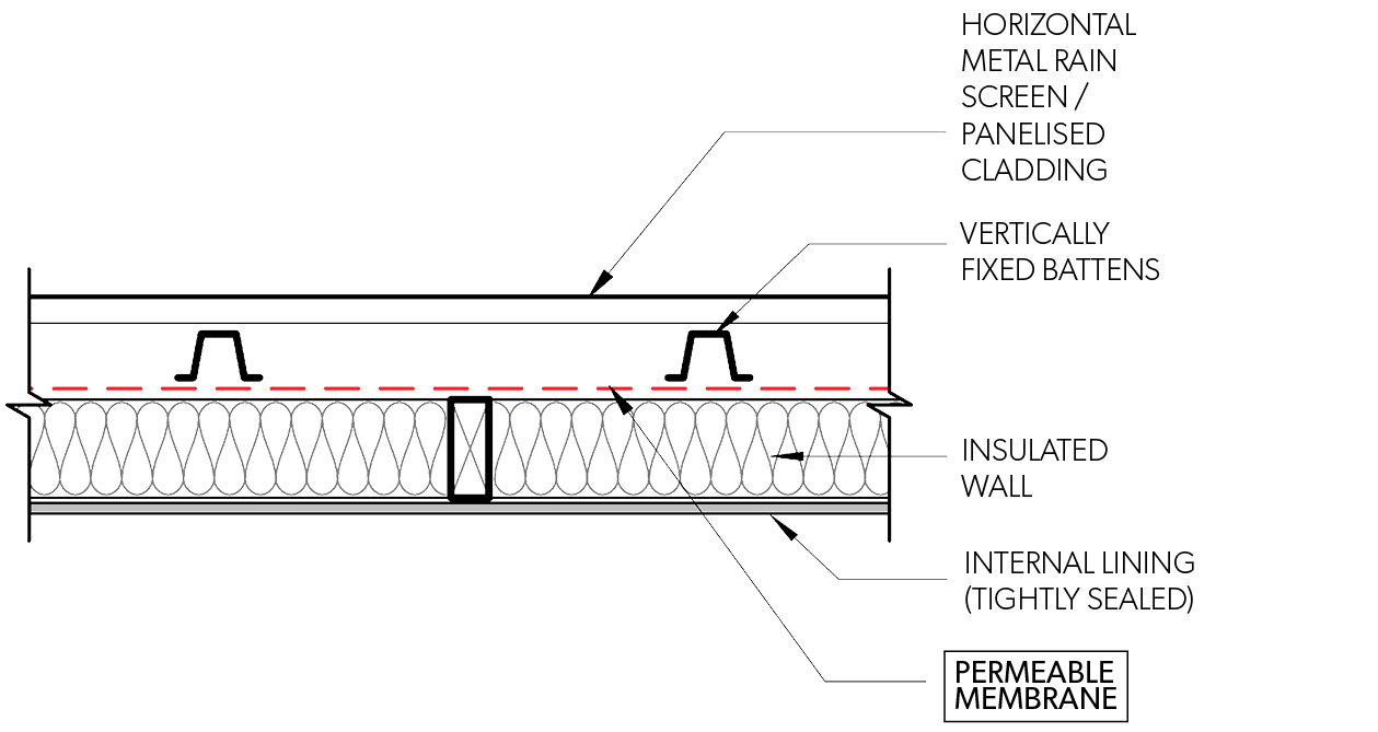
Figure F CM SSMPI 004 - Plan View - Panelised Profile - Horizontal Fix
Vapour Control Membrane (VCM) Classification AS/NZS 4200.1:2017
| Class | VCM Category | Min (≥) | Max (<) |
| Class 1 | Vapour Barrier | 0.0000 | 0.0022 |
| Class 2 | 0.0022 | 0.1429 | |
| Class 3 | Vapour Permeable | 0.1429 | 1.1403 |
| Class 4 | 1.1403 | No max | |
| ASTM-E96 Method B Wet Cup–23°C 50%RH | |||
Table Notes:
- Vapour permeance is the inverse of vapour resistance. It shall be calculated as follows: Vapour permeance μg/N.s = 1/ (Vapour resistance MN.s/g)
- AS/NZS 4200.1:2017