KingKlip® 700 Non-Cyclonic for SA | WA
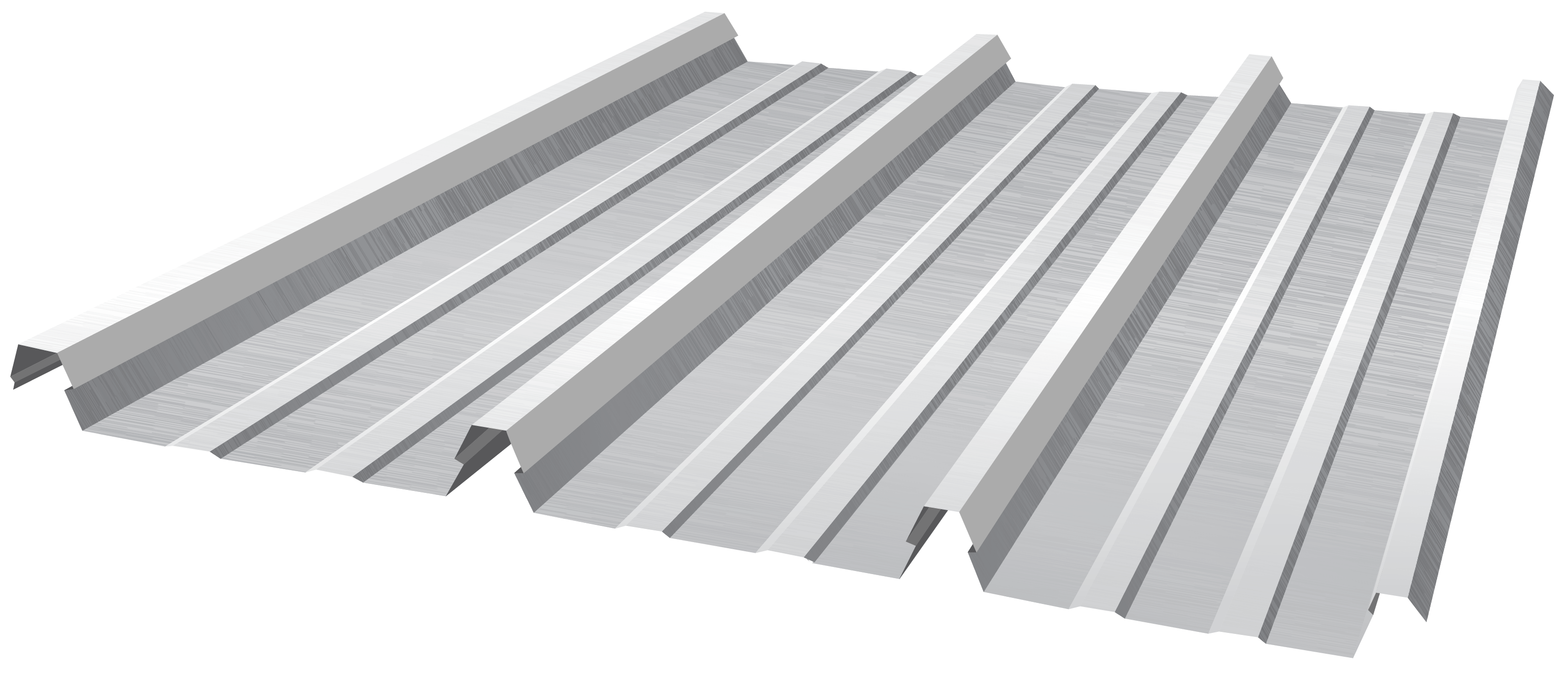
Material Specifications
| Property | Notes | |||
| Base Metal Thickness (mm) | 0.42 | 0.48 | BMT | |
| Mass / Unit Length | ZINCALUME® | 3.23 | 3.67 | kg/m |
| COLORBOND® | 3.26 | 3.70 | ||
| Mass / Unit Area | ZINCALUME® | 4.61 | 5.24 | kg/m2 |
| COLORBOND® | 4.65* | 5.28* |
||
| Minimum Yield Strength | G550 | Base Steel Designation | ||
| Coating Class | Z600 (Heritage Galvanised) AM100 (COLORBOND® Steel) AM125 (ZINCALUME®) AM150 (COLORBOND® Ultra Steel) Z450 (Galvanised) | Minimum Coating g/m2 | ||
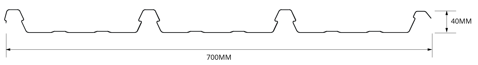
| Coverage (mm) | 700 | |||
| Tolerance | Length:+0mm, -15mm; Width: +4mm, -4mm | |||
Note:
- KingKlip 700® is manufactured from materials in accordance to AS 1397 and AS 2728. It is to be installed in accordance with AS 1562 and HB 39.
- The sectional properties are theoretical values per sheet width. These properties are gross values only.
- *is based on Standard COLORBOND®; single-sided material. For other painted steel options please contact a Fielders® representative.
Rainfall Capacity
For further information, please refer to sections "Rainfall Intensity" and "Water Carrying Capacity and Rainwater Run-Off".
Non-Cyclonic Load Span Tables
The design pressures and allowable spans have been determined from tests carried out in accordance with the following Australian Standards: AS 1562.1:1992, “Design and installation of sheet roof and wall cladding – Metal” and AS 4040:1992, “Methods of testing sheet roof and wall cladding”.
All values are applicable for fixing into a minimum steel support thickness of 1.0mm.
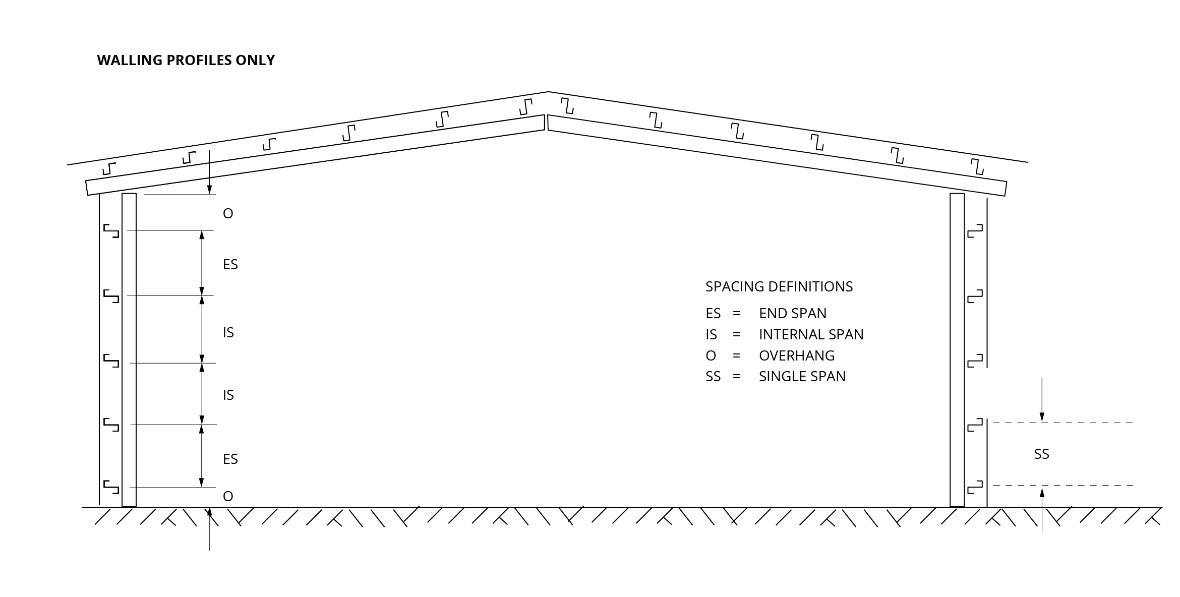
End Spans, Internal Spans and Overhangs illustrates the terminology end spans, internal spans, and overhangs and their reference to the supporting substructure. This terminology has been used in the following Maximum Recommended Span and Wind Load Capacity tables.

Figure KK NC 002 Roofing and Walling: End Spans, Internal Spans and Overhangs
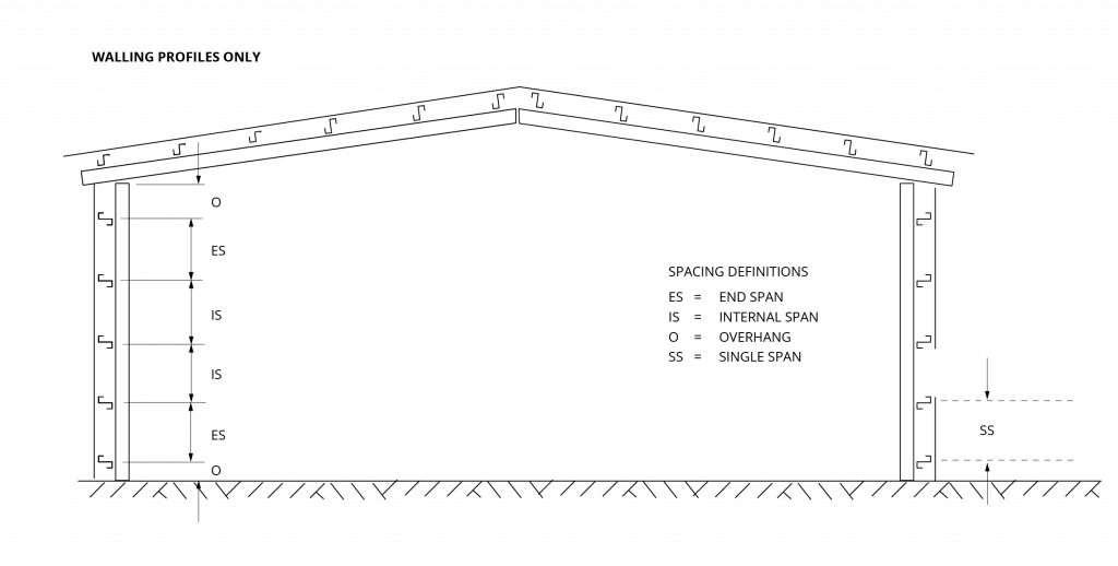 Figure KK NC 003 Walling only: End Spans, Internal Spans and Overhangs
Clip
KingKlip® 700 WA Non cyclonic S-Clip Concealed Fix Clip System
Wind Pressure Capacities: 0.42mm BMT
| Span (mm) | End Span | Internal Span | ||
| Serv. (kPa) | Strength (kPa) | Serv. (kPa) | Strength (kPa) | |
| 900 | 2.03 | 4.67 | 1.94 | 3.69 |
| 1200 | 1.91 | 3.23 | 1.70 | 3.17 |
| 1500 | 1.87 | 3.17 | 1.70 | 3.15 |
| 1800 | 1.61 | 2.75 | 1.70 | 2.93 |
| 2100 | 1.37 | 2.34 | 1.70 | 2.66 |
| 2400 | 1.16 | 1.93 | 1.59 | 2.35 |
| 2700 | 0.97 | 1.57 | 1.46 | 2.03 |
| 3000 | 0.82 | 1.28 | 1.32 | 1.78 |
Note:
- Values are based on min. 3 fixings per clip into steel supports with a minimum base metal thickness of 1.0mm.
- Values are based on no insulation under the sheeting.
- Serv. denotes serviceability
Wind Pressure Capacities: 0.48mm BMT
| Span (mm) | End Span | Internal Span | ||
| Serv. (kPa) | Strength (kPa) | Serv. (kPa) | Strength (kPa) | |
| 900 | 2.89 | 5.88 | 2.58 | 4.78 |
| 1200 | 2.68 | 4.49 | 2.54 | 4.29 |
| 1500 | 2.68 | 3.76 | 2.54 | 3.96 |
| 1800 | 2.62 | 3.23 | 2.34 | 3.30 |
| 2100 | 2.55 | 2.79 | 2.14 | 2.93 |
| 2400 | 1.80 | 2.31 | 1.90 | 2.68 |
| 2700 | 1.26 | 1.86 | 1.68 | 2.52 |
| 3000 | 0.95 | 1.50 | 1.47 | 2.22 |
Note:
- Values are based on min. 3 fixings per clip into steel supports with a minimum base metal thickness of 1.0mm.
- Values are based on no insulation under the sheeting.
- Serv. denotes serviceability.
Maximum Recommended Roof Cladding Span Non-Cyclonic
| Wind Region | Base Metal Thickness (mm) | Terrain Category 3 | |
| End (mm) | Internal (mm) | ||
| A | 0.42 | 2000 | 2700 |
| 0.48 | 2600 | 3000* | |
| B | 0.42 | 1800 | 2600 |
| 0.48 | 2100 | 3000* | |
Importance Level 2
Max. Roof Height = 10m External
Pressure Coefficient
Cpe = -0.65 (walling)
Cpe = -0.9 (roofing)
Internal Pressure Coefficient
Cpi = 0.2
Local Pressure Factor,
Kl = 2.0 (end & single spans)
Kl = 1.0 (internal spans)
Table KK RS NC 002A - KingKlip 700® Non-Cyclonic
Note:
- Values are based on min. 3 fixings per clip into steel supports with a minimum base metal thickness of 1.0mm.
- *Spans in excess of 3000mm may be available subject to enquiry.
Maximum Recommended Wall Cladding Span Non-Cyclonic
| Wind Region | Base Metal Thickness (mm) | Terrain Category 3 | |
| End (mm) | Internal (mm) | ||
| A | 0.42 | 2900 | 3000* |
| 0.48 | 3000* | 3000* | |
| B | 0.42 | 2300 | 3000* |
| 0.48 | 2550 | 3000* | |
Importance Level 2
Max. Roof Height = 10m External
Pressure Coefficient
Cpe = -0.65 (walling)
Cpe = -0.9 (roofing)
Internal Pressure Coefficient
Cpi = 0.2
Local Pressure Factor,
Kl = 2.0 (end & single spans)
Kl = 1.0 (internal spans)
Table KK RS NC 001A - KingKlip 700® Non-Cyclonic
Note:
- Table data is based on supports of 1mm BMT.
- *Spans in excess of 3000mm may be available subject to enquiry.
- For walls: the data are based on pressures
Insulation
Care needs to be taken when installing insulation with roof sheeting. When insulation thickness up to 50mm are installed the screws detailed in Table KK RF NC 001 may need to be increased depending on the thickness and density of the insulation. When the screw is properly tightened into metal there should be a minimum of three (3) threads protruding past the support being fixed in to. For timber the screw must penetrate the timber as much as the screws detailed in Table KK RF NC 001 do without insulation. For insulation thicknesses greater than 50mm Fielders® recommend the use of a thermal spacer to help maintain Rw values as well as minimising any bulging in the profile caused by the insulation. Please contact your local Fielders Representative to determine the most suitable spacer bracket for your project.
Fasteners - Clip Fixing
Fasteners must be selected to match the life expectancy of the cladding material. Recommendations from fastener manufacturers should be sought.
Only fasteners complying with AS 3566:2002 and those that are compatible with the roofing material should be used for its fastening.
Crest or Pan Fixing
KingKlip 700® can be crest fixed to timber or steel supports. Fasteners should not be located less than 30mm from the ends of the sheets. Contact your local Fielders® Representative for capacity information.
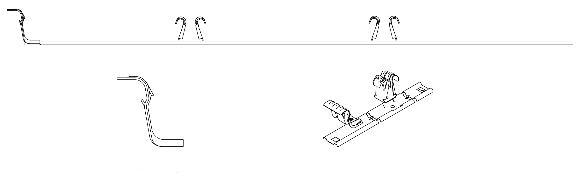
Concealed Fix Clipping System
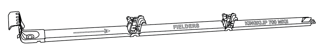
Figure KK MKIII KingKlip® NC 001 - Concealed Fix Clipping System
Recommended Fasteners Concealed-Fixed
| Supports | Clip Fixed |
| Fix to Steel Single thickness steel ≥1.0mm BMT up to 3.0mm BMT | 5.4-14x25, Vortex, HH 12-14x30 Concealed Hex Teks |
| Fix to Steel Total Lapped thicknesses of ≥1.0mm BMT up to 3.8mm BMT | 5.4-14x25, Vortex, HH 12-14x30 Concealed Hex Teks |
| Fix to Timber Hardwood (J1-J3) | 5.4-14x25, Vortex, HH |
| Timber Softwood (J4) | 5.4-14x25, Vortex, HH |
Notes:
1. Use three (3) fasteners per clip
2. Recommended fasteners shown in Table KK RF NC 001 are for construction without insulation
KingKlip® 700 Installation Procedure
Refer to "Maintenance and Care" for general handling instructions.
Preparation
Before starting work ensure that:
- The supports for your cladding are truly in the same plane, this is critical if the roof slope is ≤5°.
- The minimum roof slopes conform to our recommendations.
- The overhangs of sheets from the top and bottom supports don’t exceed our recommendations.
- The first and last supports and clips should be at least 75mm from each end of the sheet to keep maximum holding power.
Make any necessary adjustments before you start laying sheets because they will be difficult to rectify later.
ORIENT SHEETS BEFORE LIFTING
Consider which end of the building is best to start from. For maximum weather-tightness, start laying sheets from the end of the building that will be downwind of the worst-anticipated or prevailing weather (Figure 1). It is much easier and safer to turn sheets on the ground than up on the roof. Before lifting sheets on to the roof, check that they are the correct way up and the overlapping side is towards the edge of the roof from which installation will start. Place bundles of sheets over or near firm supports, not at mid span of roof members.
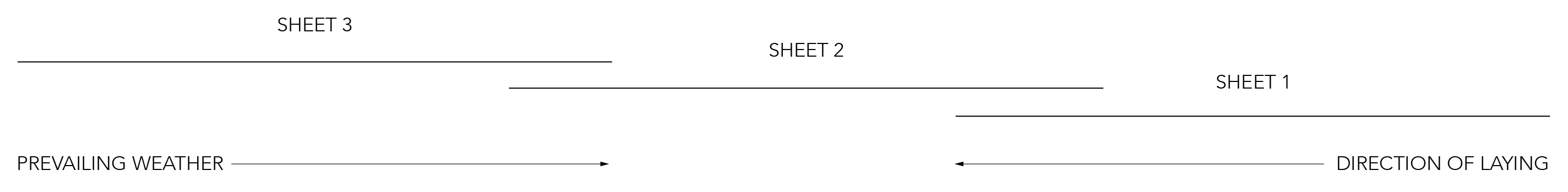
Figure 1
Step 1
Lay and fix wire mesh to the supports and glass wool insulation in accordance with the appropriate building requirements.
Step 2
Position the first clips on each support by placing onto the support nearest the roof edge (Figure 2).

Figure 2
Step 3
Fix the first clip on the support so they point in the direction of laying. Ensure the clip is 90 degrees to the edge of the sheet.
Step 4
Align the clips using a string line (Figure 3) or the first sheet as a straight edge to align the clips as you fix a clip to each support working towards the high end of the roof.

Figure 3
Step 5
Drive hex-head screws through the top of the clip, into the support.
Step 6
Work along the edge of the roof, ensuring it aligns correctly at its ends in relation to the gutter and ridge or parapet or transverse wall.
Step 7
Position the first sheet so that it overhangs the desired amount (minimum 50mm) to the gutter. It is important to ensure this first sheet is placed square to adjacent edges (Figure 4a)
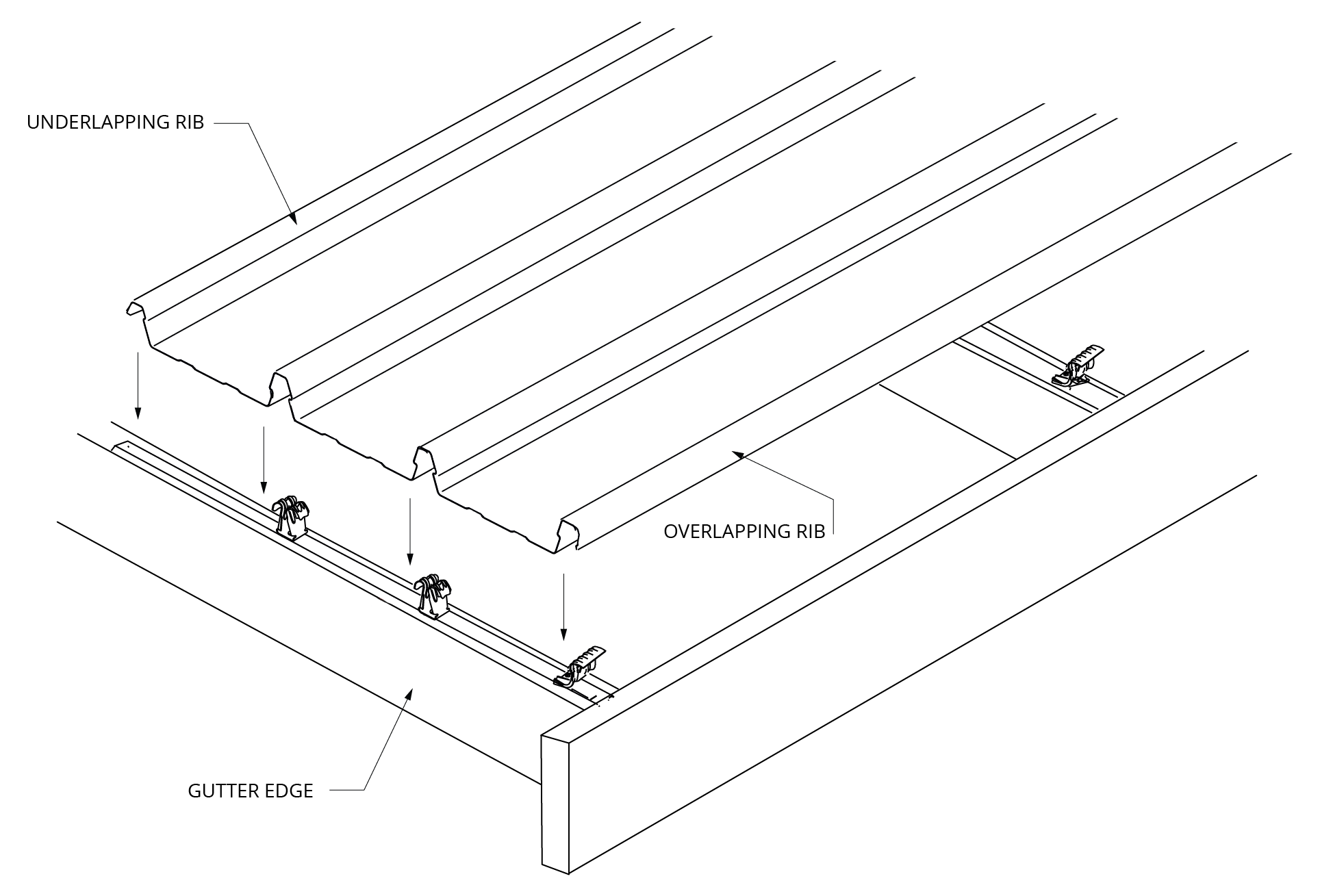
Figure 4a
Step 8
Engage the sheet with clips using vertical foot pressure on all the ribs over each clip.
Step 9
Fix the initial overlapping rib of the first sheet using an ‘S’ clip. (For laying sequence, see Figure 4b.)
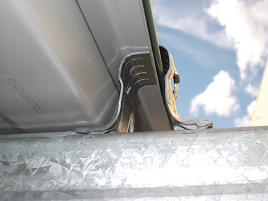
Figure 4b
Step 10
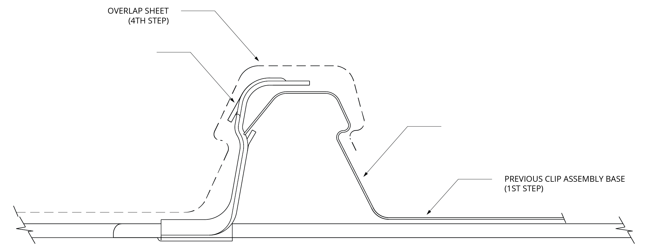
Fix each next row of clips one to each support by engaging the front of the clip assembly onto the underlap rib of the preceding sheet engaging the spur of the clip to the leading edge of the previous sheet (Figures 5 & 6). Be sure the clip is at 90° to the edge of the sheet.
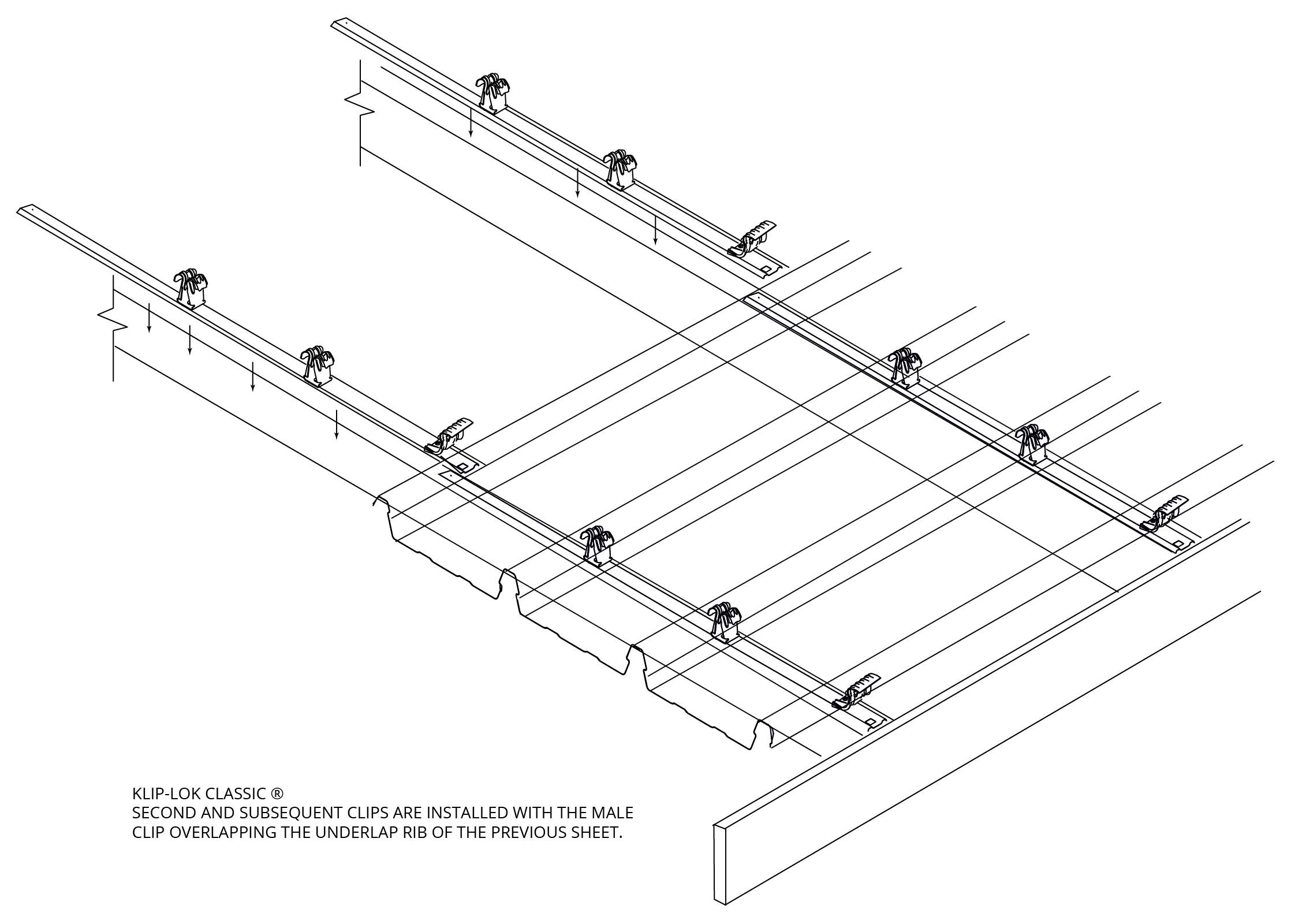
Figure 5
Figure 6
Step 11
As before, place the next sheet over its clips ensuring you also engage the edge of the preceding sheet.
Step 12
Fully engage the two sheets along the overlapping rib. You can do this by walking along the full length of the sheet with one foot in the centre pan of the previous sheet and the other foot applying vertical pressure to the top of the interlocking ribs at regular intervals. It is recommended that you don’t walk in the unsupported pan beside the underlapping rib (Figure 7).
With long spans, additional care may be required to ensure the overlapping rib adequately engages onto the underlapping leg. Care should be exercised due to the potential instability of the side-lap when it is not adequately engaged (interlocked).
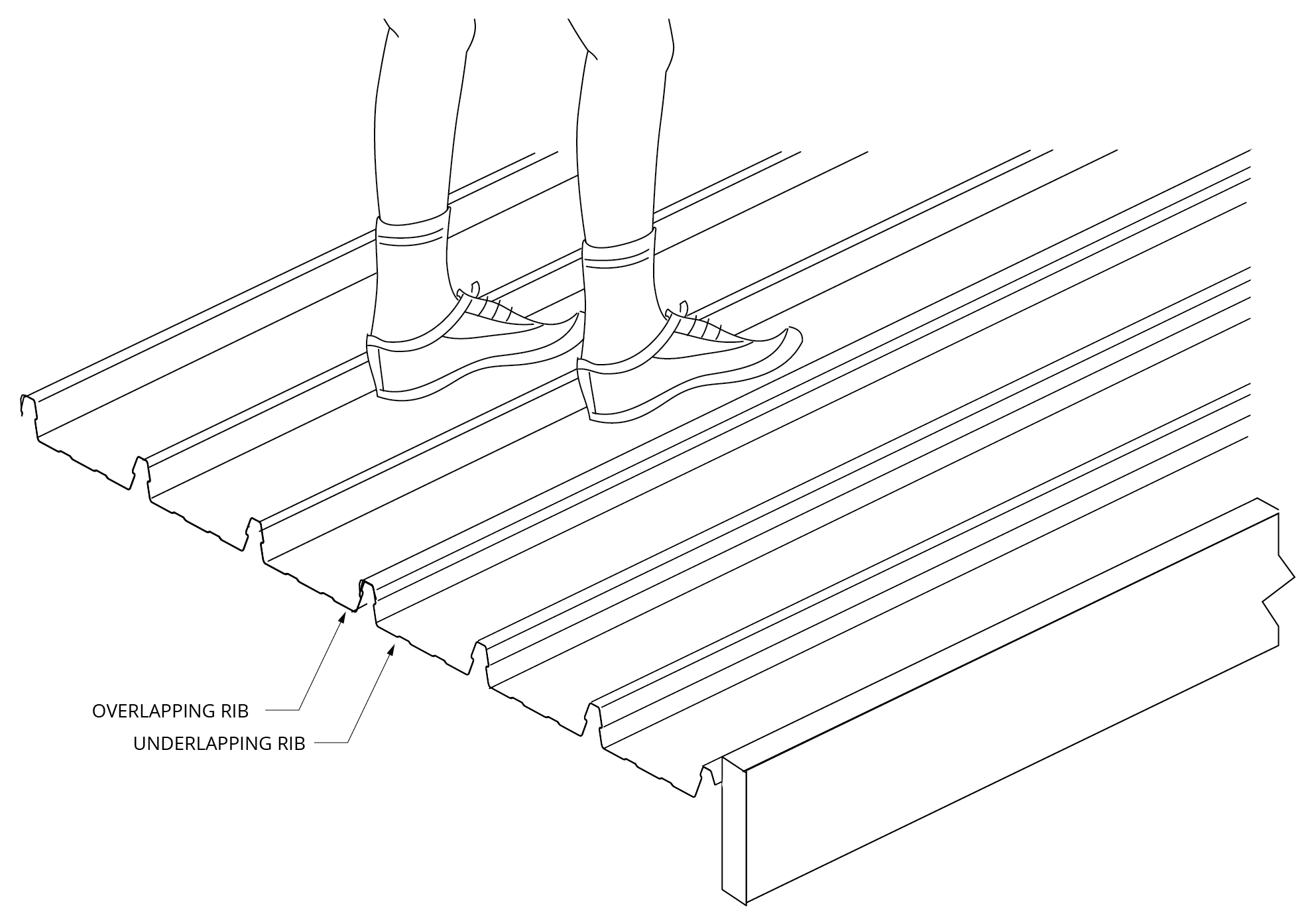
Figure 7
Step 13
Similarly, engage all the clips by applying vertical foot pressure to the top of the other two ribs over each clip.It is essential that the sheets interlock completely. It is important that your weight is fully on the sheet you are installing.
Step 14
Fit an ‘S’ clip at the last rib of the profile (similar to step 9 when the sheet was started). Both starting and finishing requires an ‘S’ clip.
Figure 8
CHECK ALIGNMENT OCCASIONALLY
Occasionally check that the sheets are still parallel with the first sheet, by taking two measurements across the width of the fixed sheeting. At about half way through the job, perform a similar check but take the measurements from the finishing line to aim for the final sheet to be parallel with the end of the roof. If the measurements are not close enough, lay subsequent sheets very slightly out of parallel to gradually correct the error (Figure 8).
FIX THE LAST SHEET
If the final space is less than the full width of a sheet, you can cut a sheet along its length and shorten the clips as appropriate.
Wall Installations
In walling applications, horizontal pressure will need to be applied locally to the sheets to engage the ribs. Use body pressure (torso, hand or foot) or use a rubber mallet if required. Care should be exercised due to the potential instability of the temporary worker access equipment.
To prevent KingKlip® 700 from sliding downward in the fixing clips, you should pierce-fix through each sheet under the flashing or capping, along the top of the sheets.
Box Gutter

Turning of Roof Sheeting Ends
Refer to section “Flashings, Cappings & Ends of Sheets”.
Designing Without Step Joints
Refer to section "Long Length Roofing Solutions".
Maximum Sheet Length
See section “Thermal Expansion and Contraction of Steel Sheeting”.