TRYP by Wyndham Pulteney Street Adelaide, SA

ARCHITECT:
CHROFI

STRUCTURAL ENGINEER:
Brett Aldrige


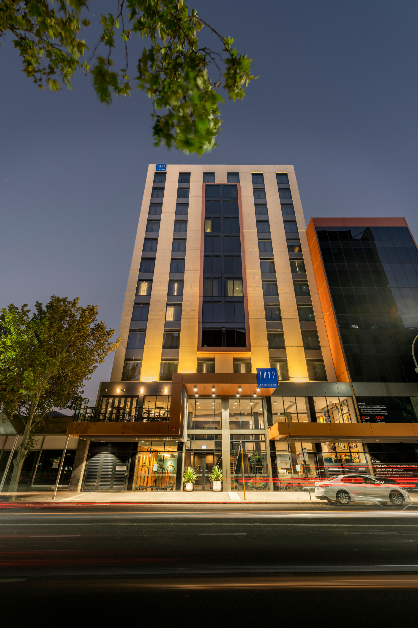
Award-Winning Design and Construction: TRYP by Wyndham Adelaide

Following the pandemic's challenges, South Australia has seen a resurgence in tourism activities, with a bustling events calendar, the reinstatement of cruise ship stops, and improved air travel links. There are promising signals of an increase in national and international visitors alike, building upon the pre-pandemic benchmark of attracting approximately 6.8 million travelers annually. 


“Adelaide has been calling out for more accommodation because capacity is often exceeded when we have events. There's been a shortage of hotels here for some time, especially with major events like the Fringe coming up,” explained Daryl Crebbin, General Manager, Marshall & Brougham Constructions. 


The construction of TRYP by Wyndham Pulteney Street Adelaide is timely, poised to cater to the increasing influx of visitors seeking to explore the region's cosmopolitan culture and rich history in arts and festivals. 


TRYP by Wyndham marks a significant milestone as the introduction of the TRYP by Wyndham brand to Australia.  This 120-room property exemplifies contemporary design and urban energy, with architecture that echo the city's vibrant lifestyle. Its city location offers guests easy access to Adelaide's rich tapestry of multicultural restaurants, lively bars, decorated laneways, and the boutique shopping experience of Adelaide Central Markets and Rundle Mall.  


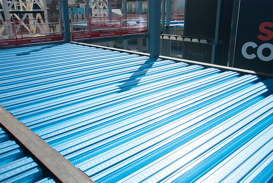
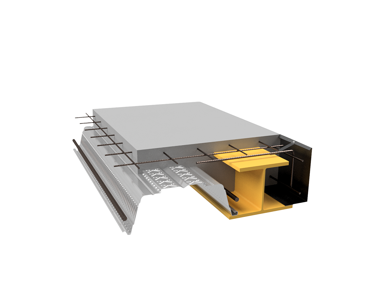
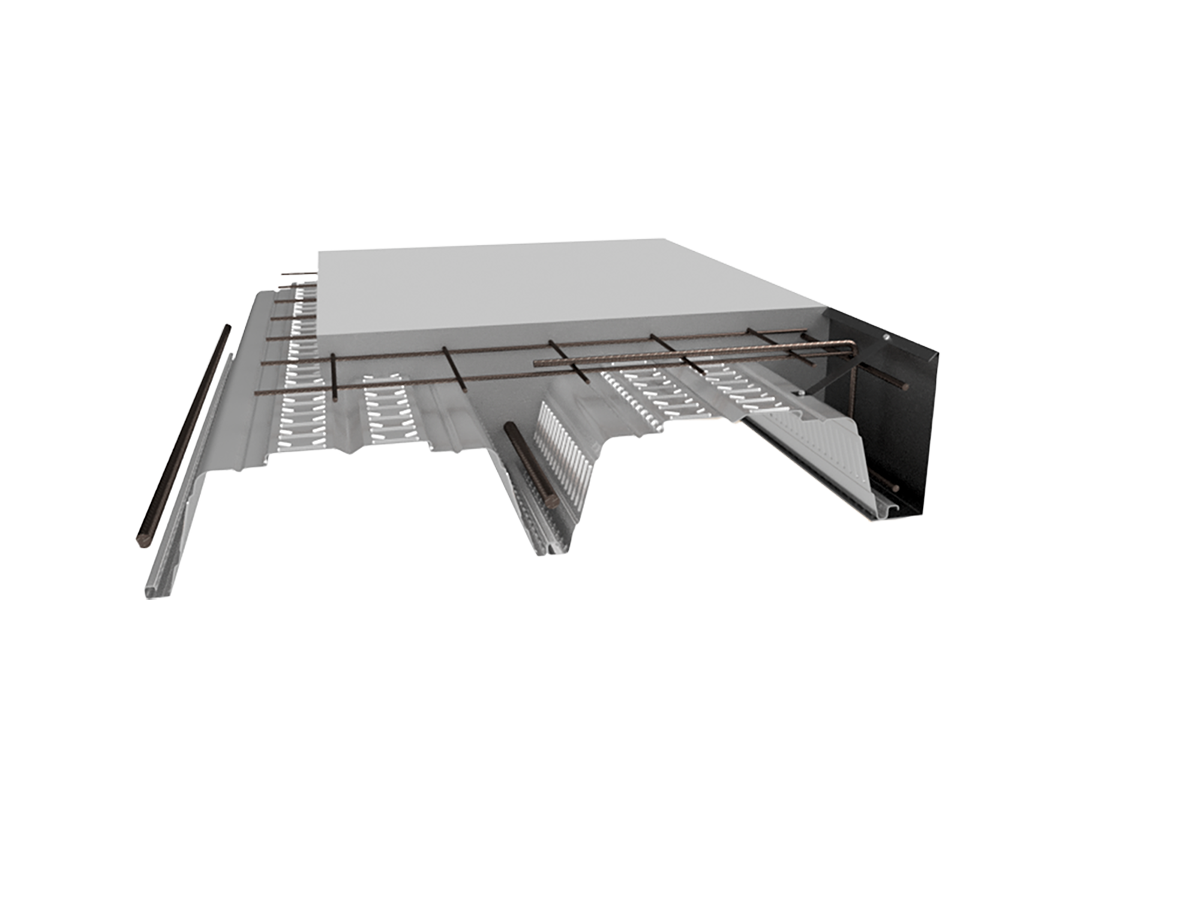
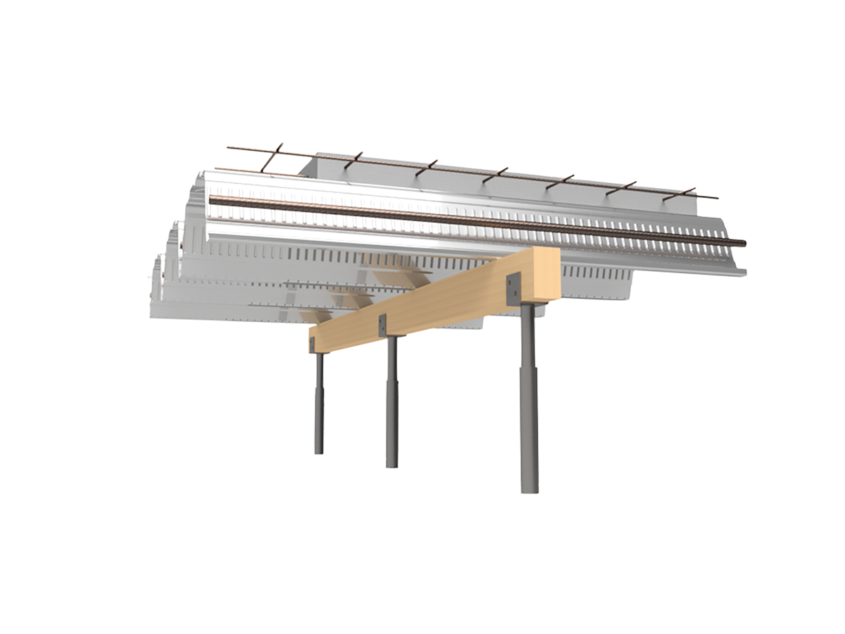
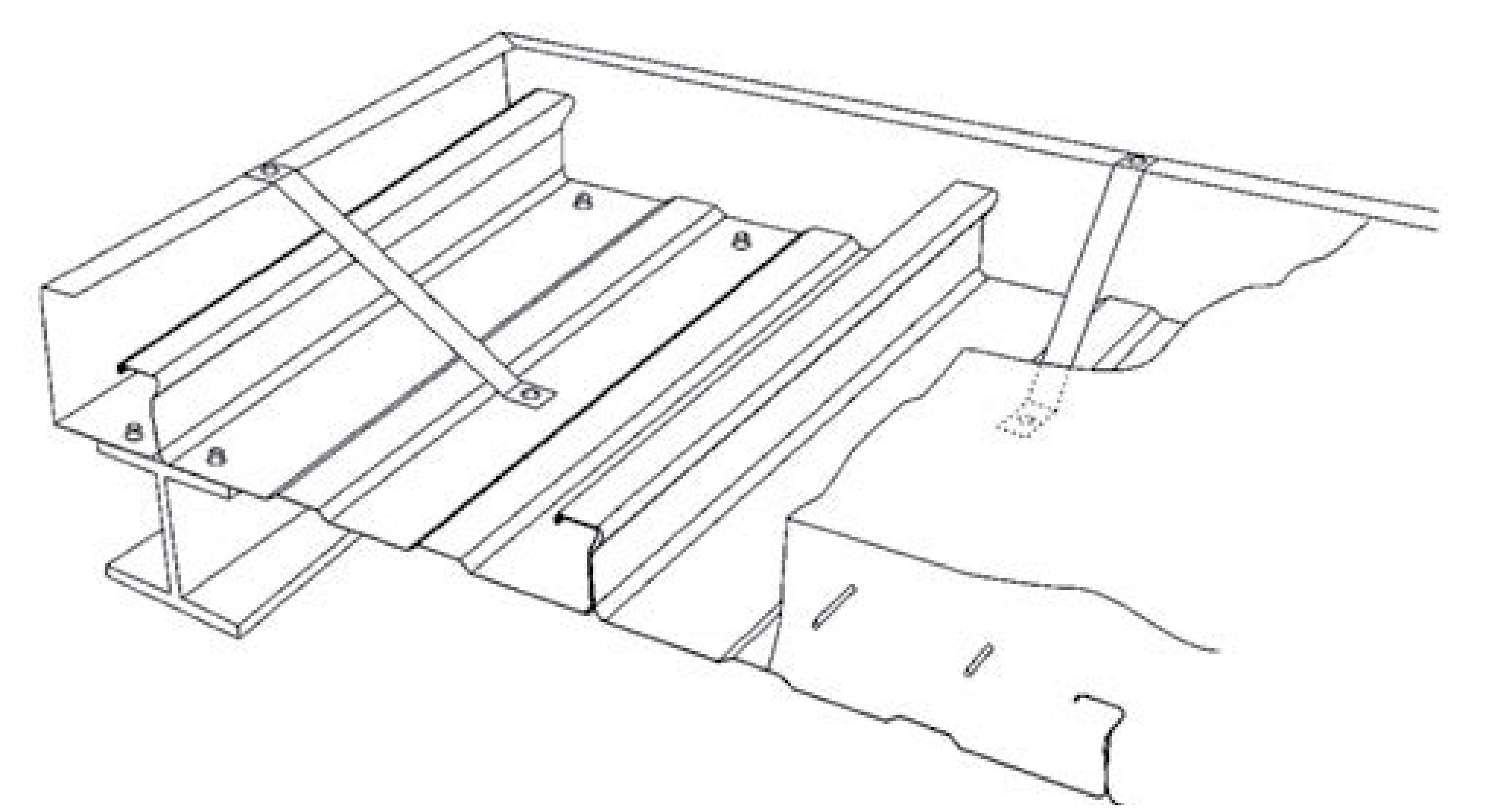
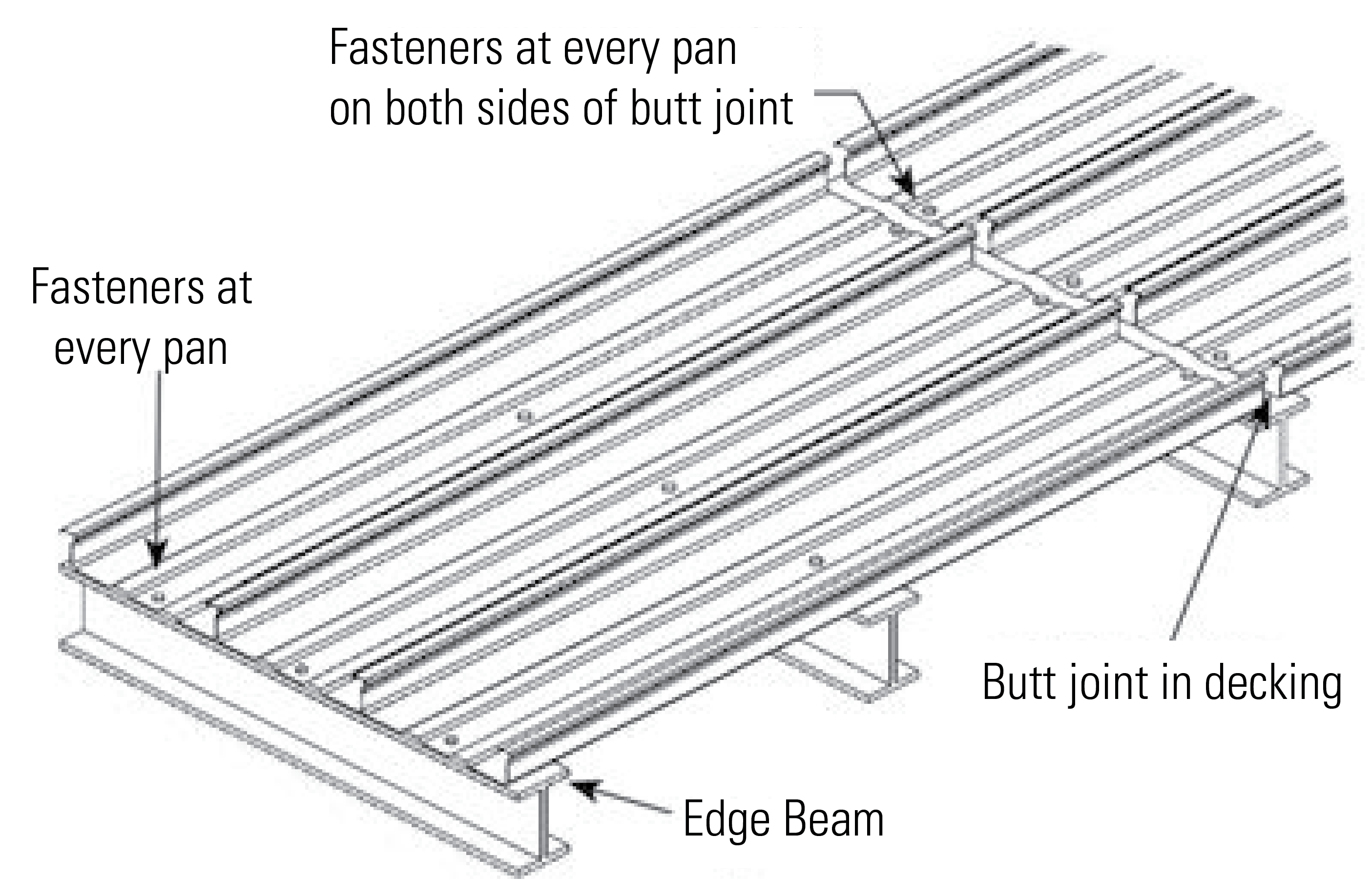
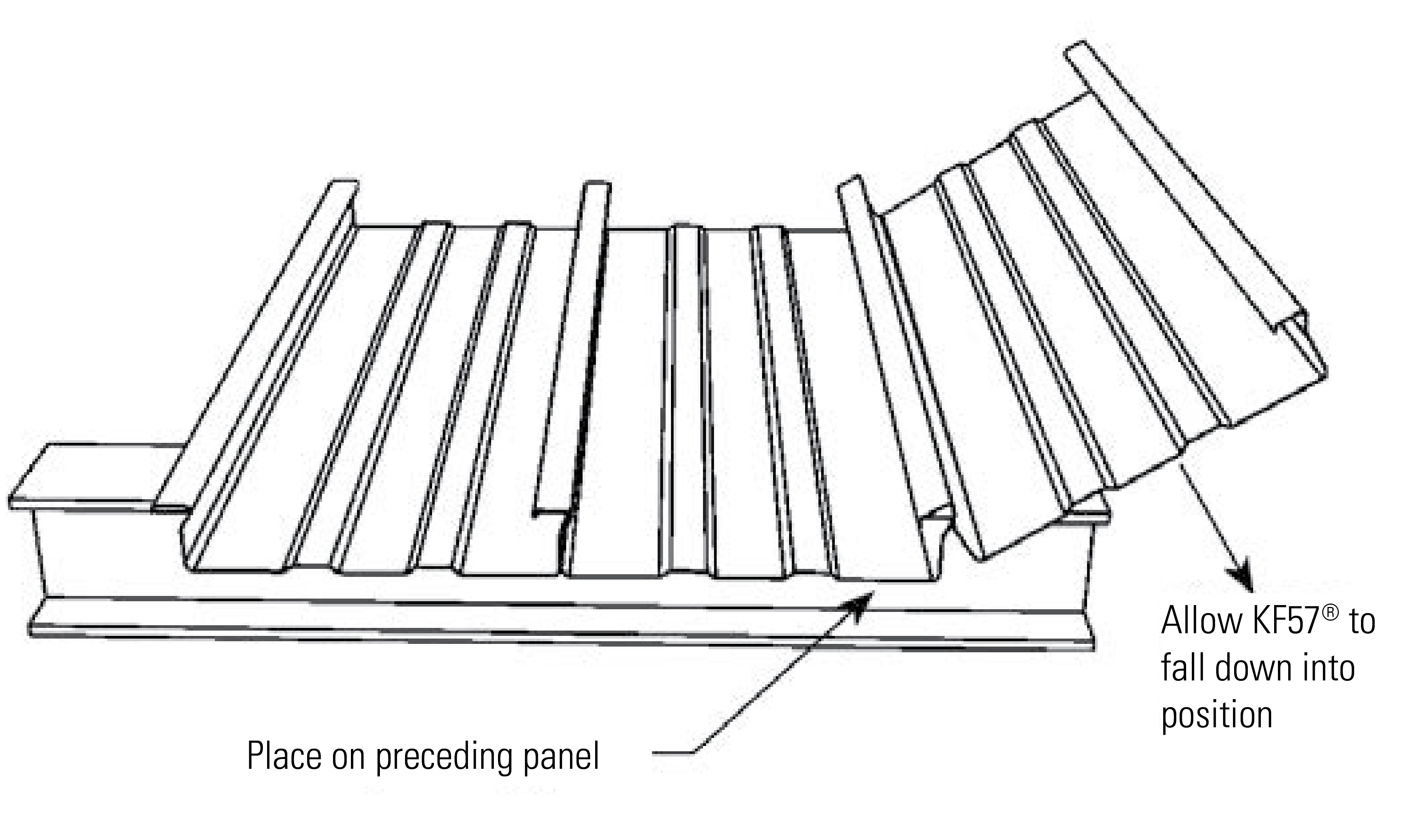
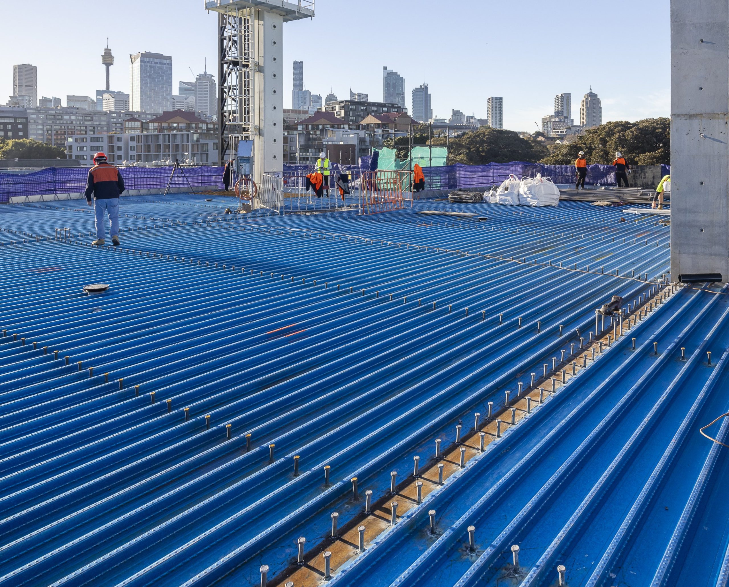
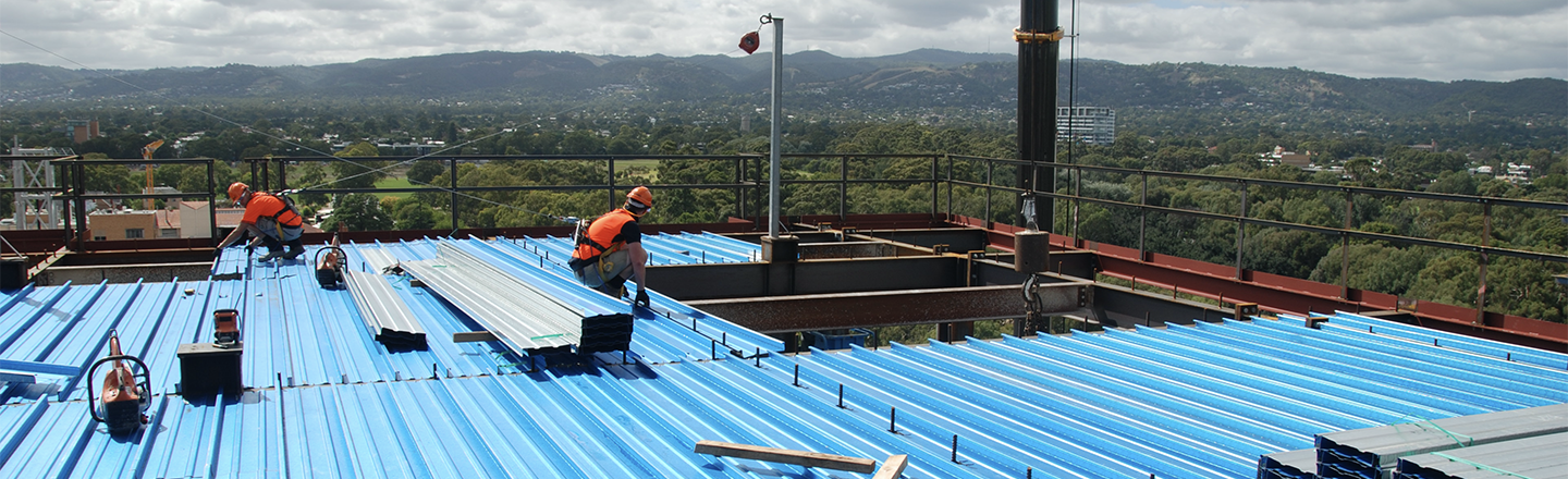
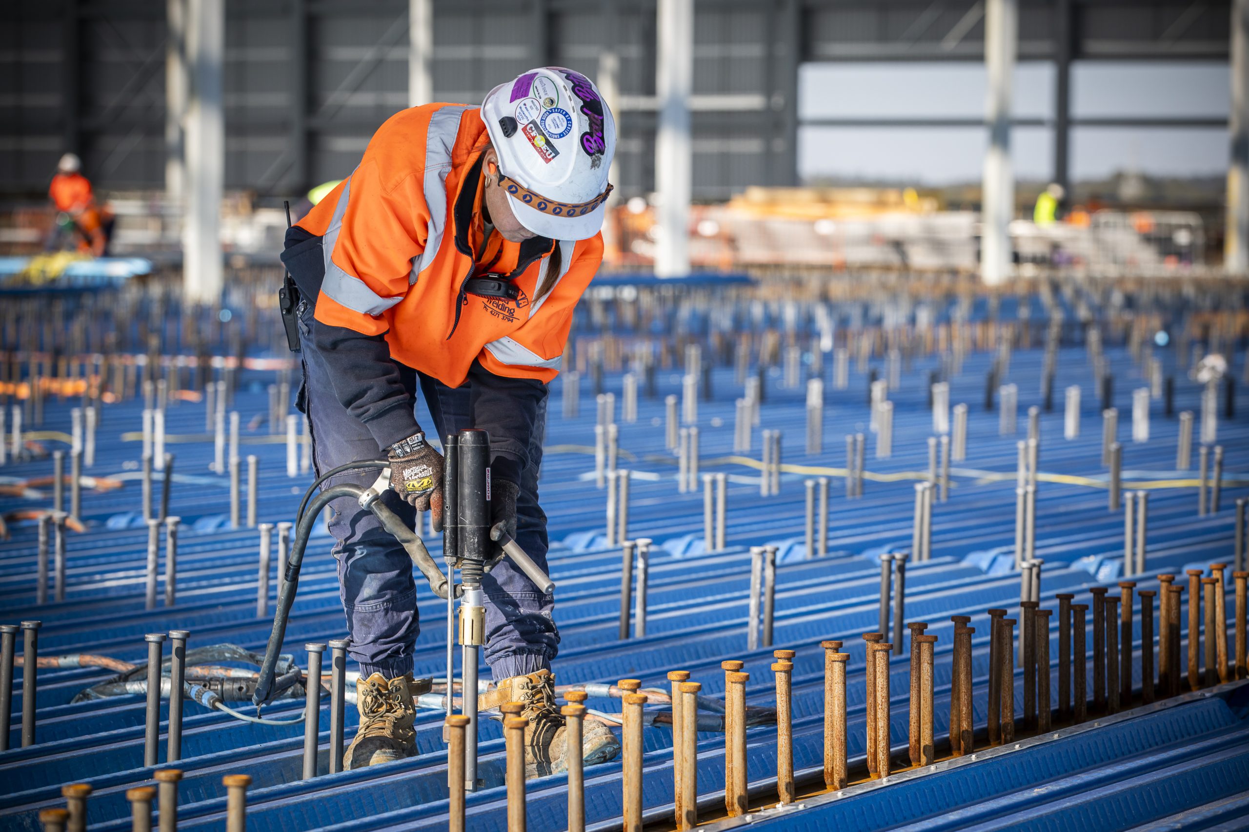
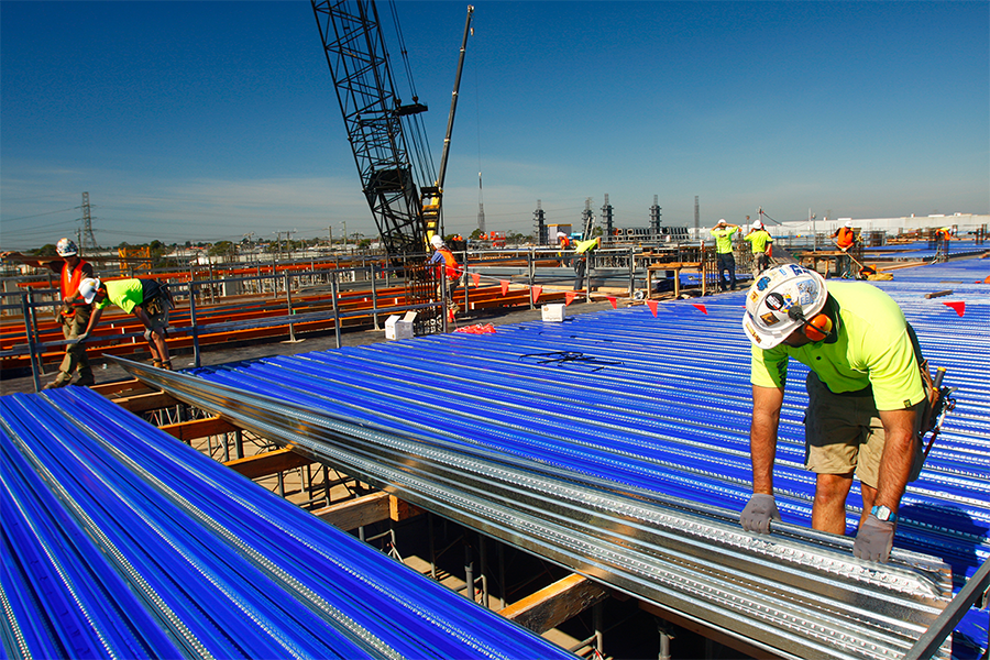
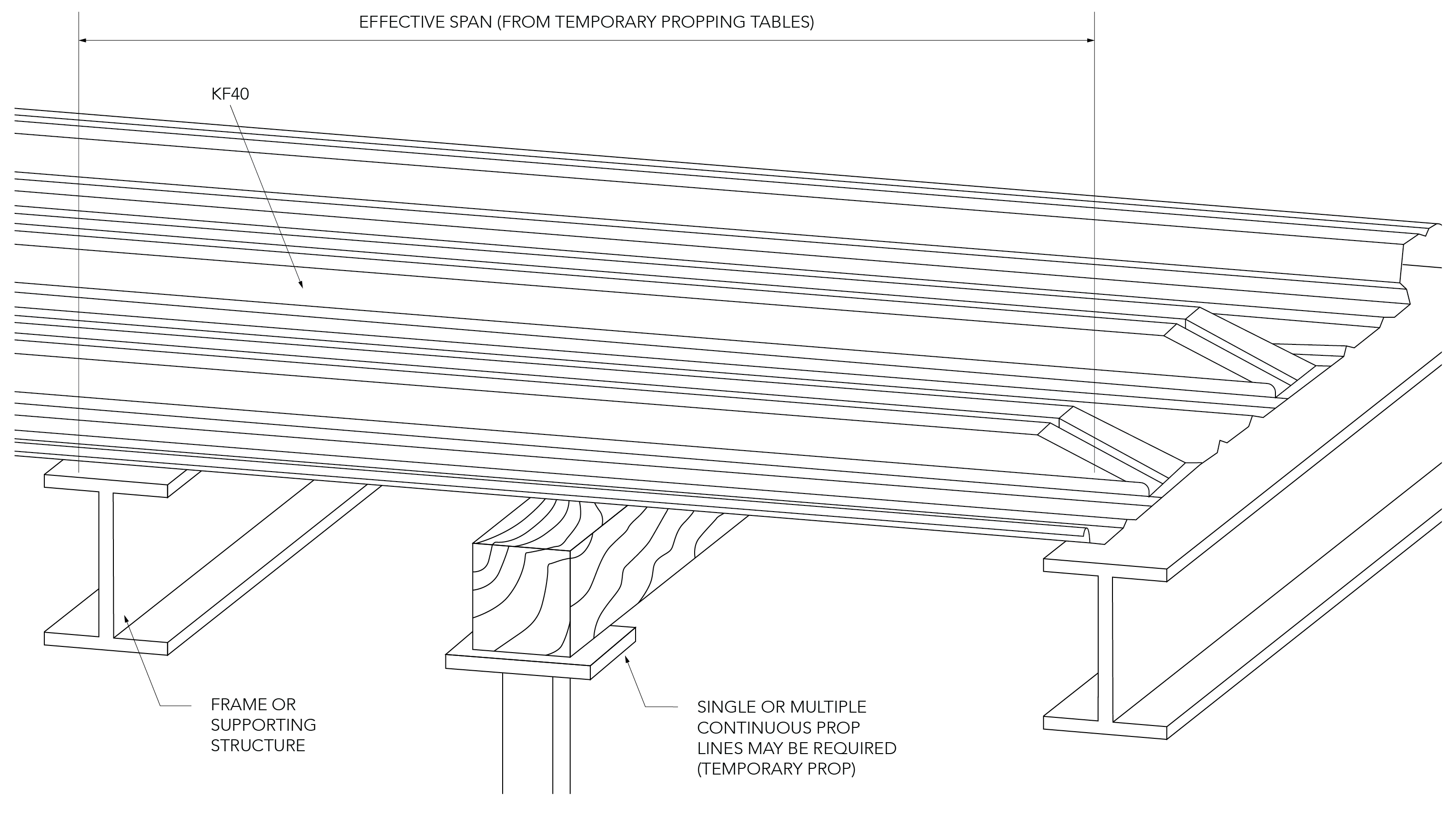
Central to its construction was the integration of Fielders' KingFlor® KF70® steel formwork system, a testament to the industry's shift towards more efficient, lightweight construction methodologies. 


Navigating site constraints

From the outset, the TRYP by Wyndham Pulteney Street Adelaide project was faced with site constraints, primarily due to the proximity of existing buildings that bordered the construction area. 


“There were some challenges on site as there were existing structures at north and south where we need to ensure no damages due to the excavations or piling therefore, underpinning and temporary supports were applied,” said Samir Hanna, Principal Structural Engineer, MLEI.  


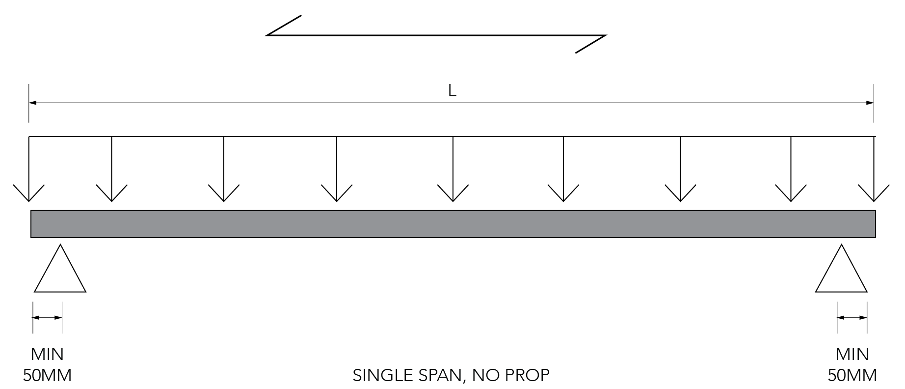
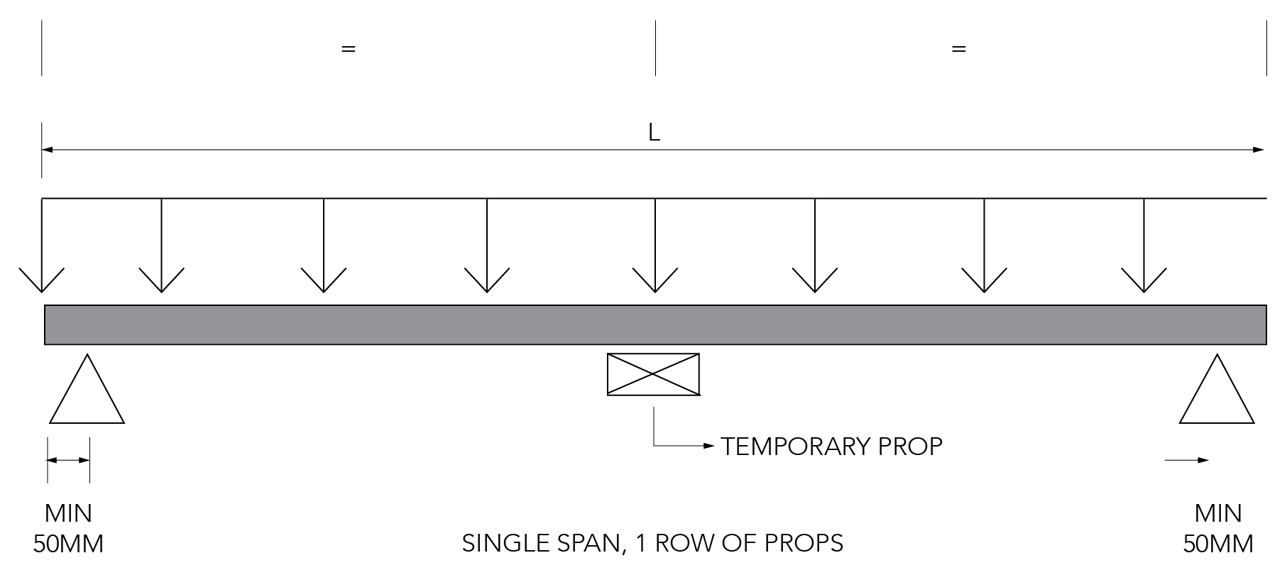
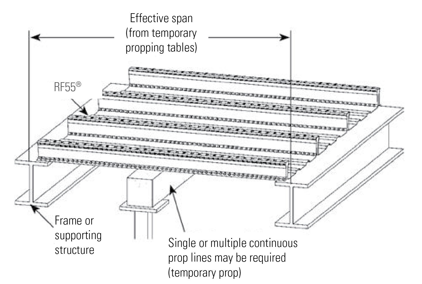
To circumvent these challenges, the project team decided on a different approach to traditional propping. 


"One of the solutions was to not have propping for the formwork and that's why a steel frame structure with the steel formwork system was used," said Daryl Crebbin. 


MLEI, the project design engineers, chose to use a known Fielders solution. “We designed the suspended slabs with KingFlor® KF70® formwork to avoid the requirement for propping” explained Samir Hanna. 


This decision, alongside the use of eco-friendly materials and unique finishes, expedited the construction process, added to the building's distinctive aesthetic, while also reducing costs. 

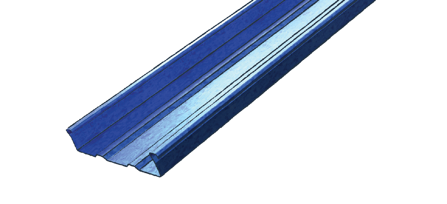
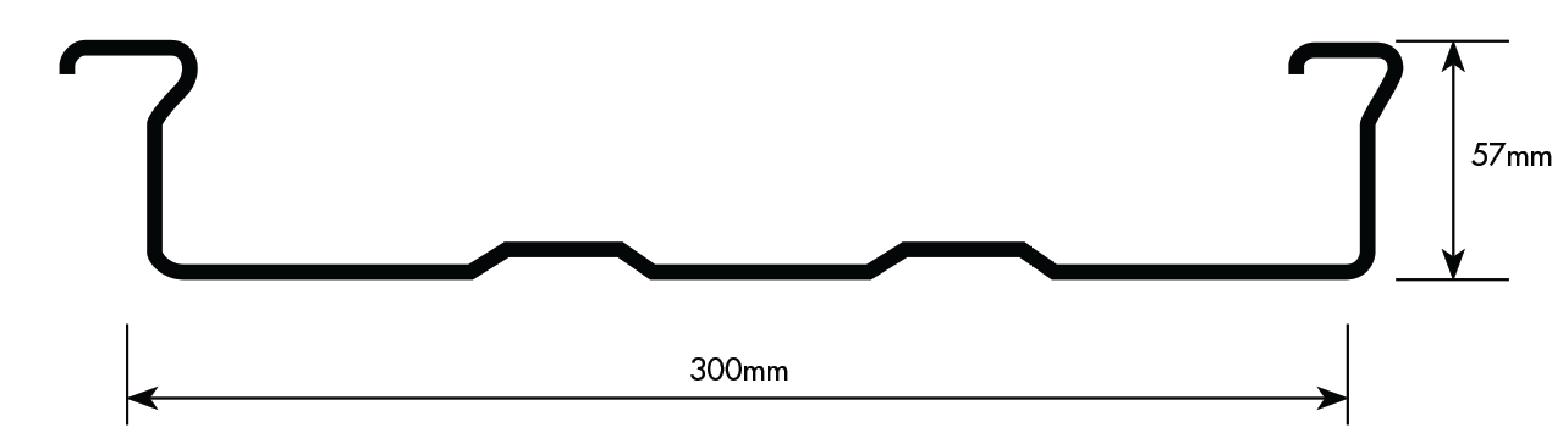
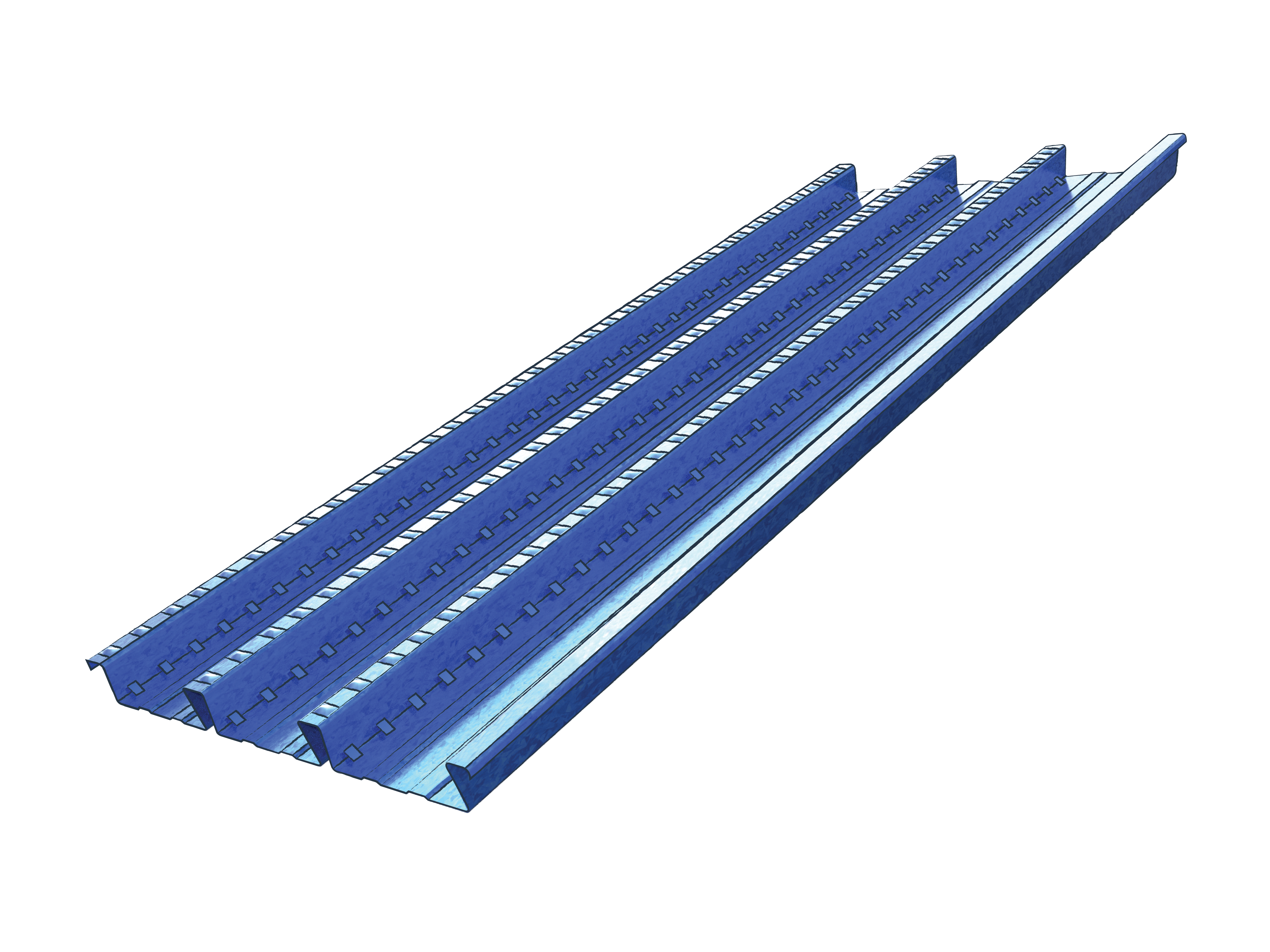
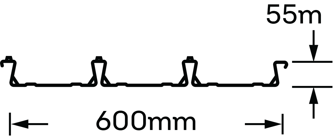
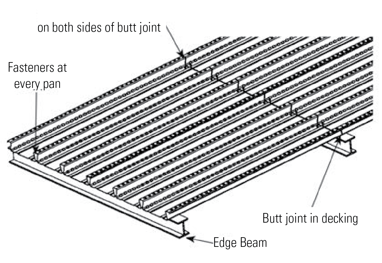
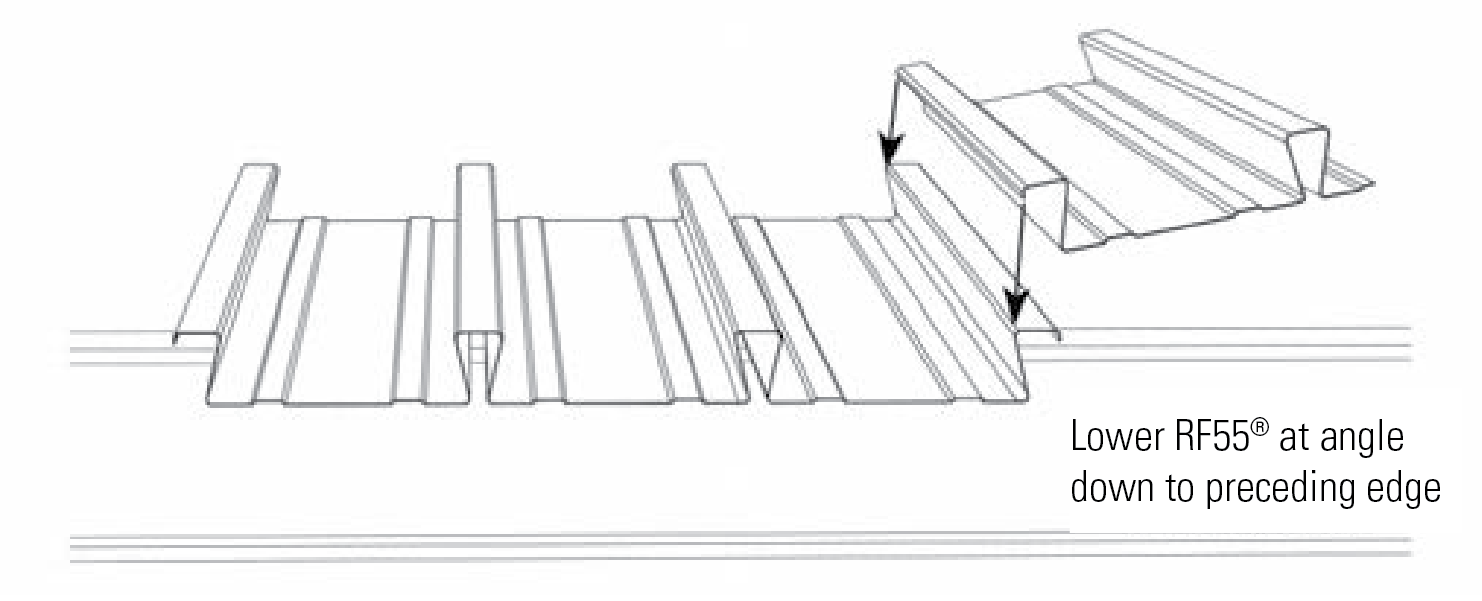
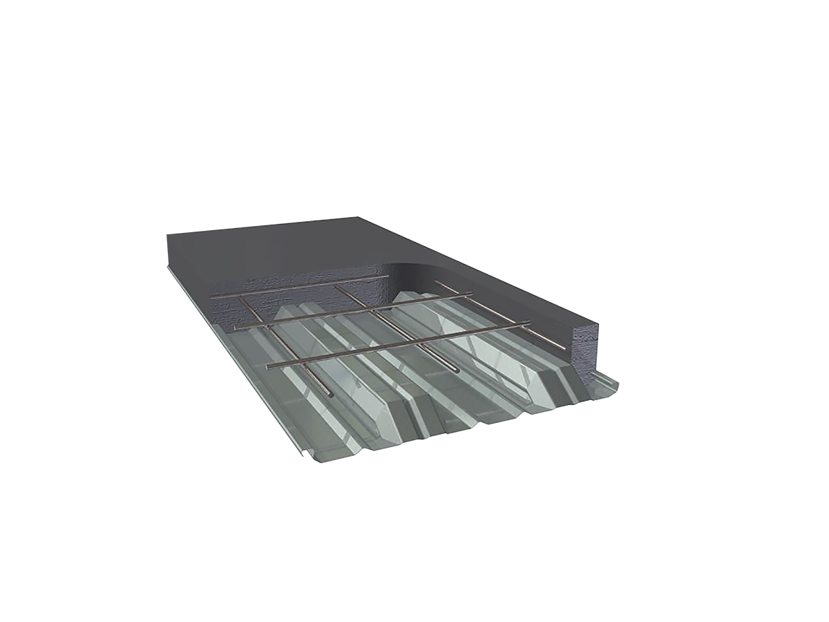
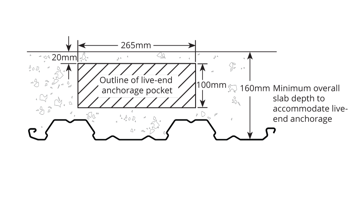
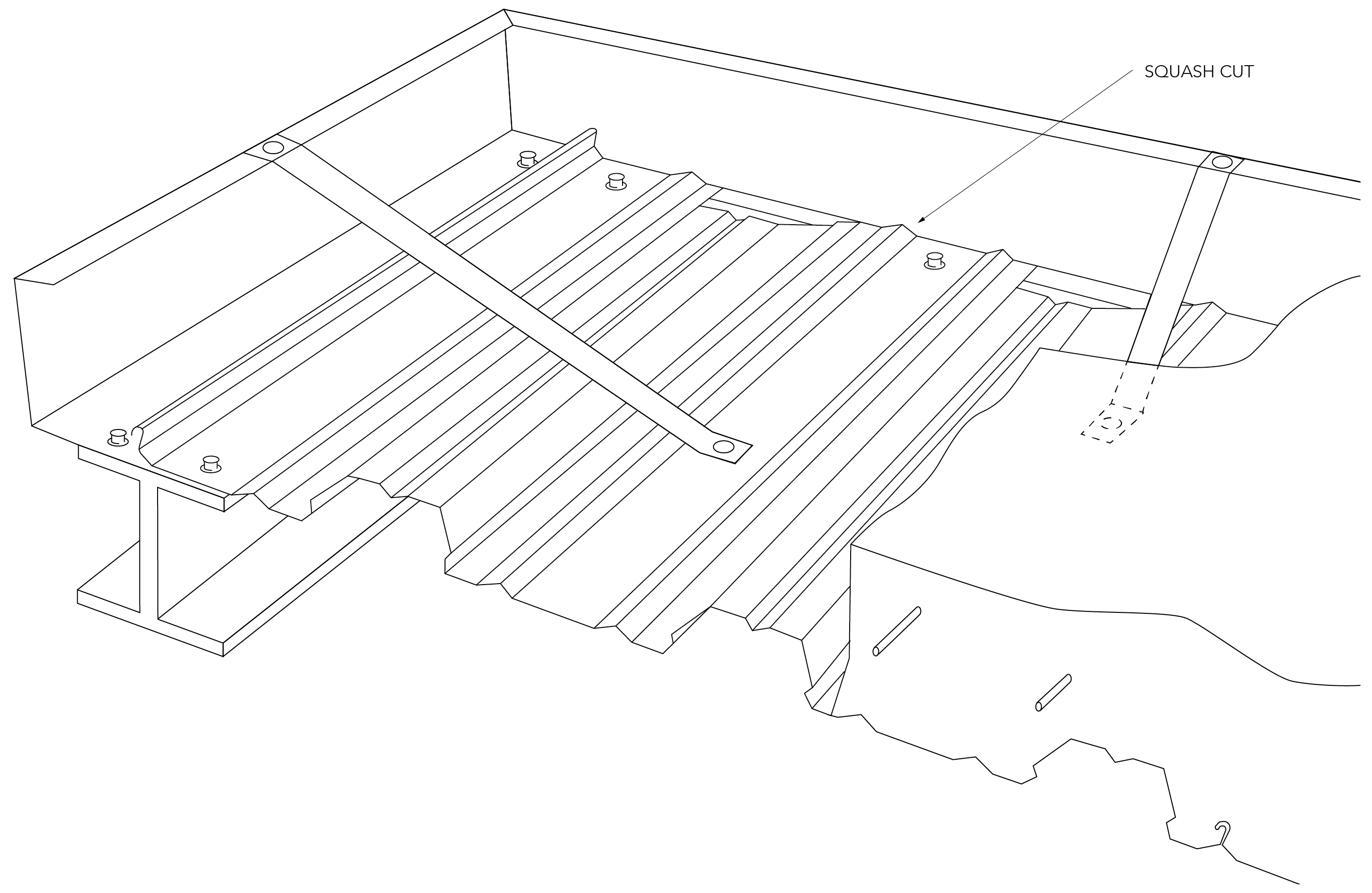
Fielders' KingFlor® KF70® Framework System

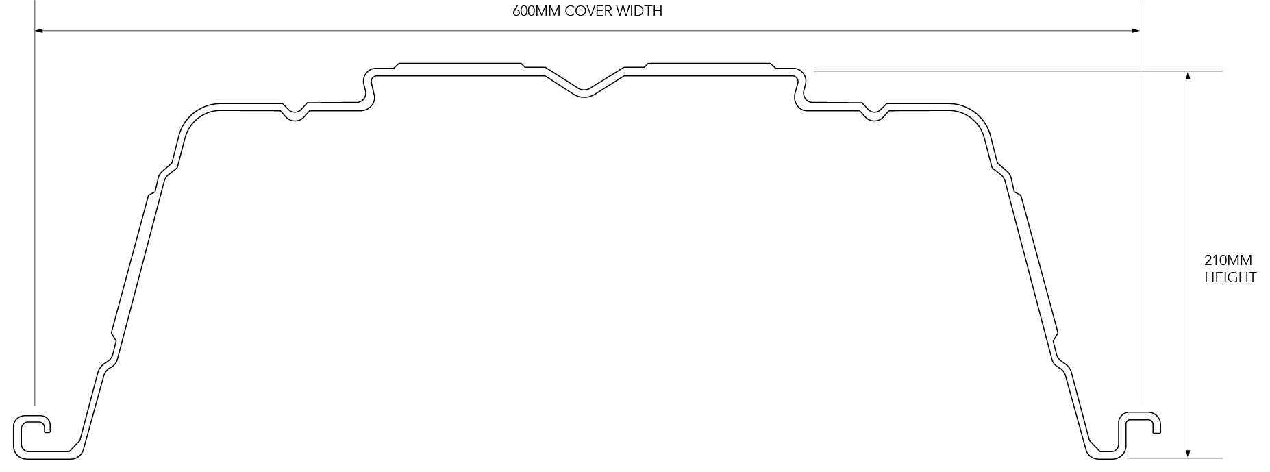
Fielders’ KingFlor® KF70® system has been recognised globally as a cost-effective composite steel formwork solution, preferred for its longer span capabilities and deeper profile compared to other formwork options 


"A key advantage of using the KingFlor® KF70® system is its ability to reduce the weight of the building,” explained Ashesh Singh, BDM - Engineering of South and Western Australia, Fielders.  


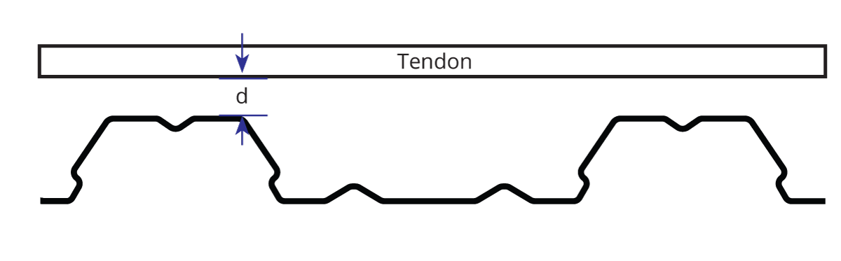
“This is achieved through the unique profile of the decking, which displaces a certain amount of concrete. The KingFlor® KF70® system displaces 26 millimeters of concrete by volume compared to a standard concrete slab. Opting for the KingFlor® KF70® system results in a lighter slab, which in turn requires a lighter foundation. This reduction in weight and material use offers significant benefits, both financially and structurally, to builders and property owners alike during construction." 


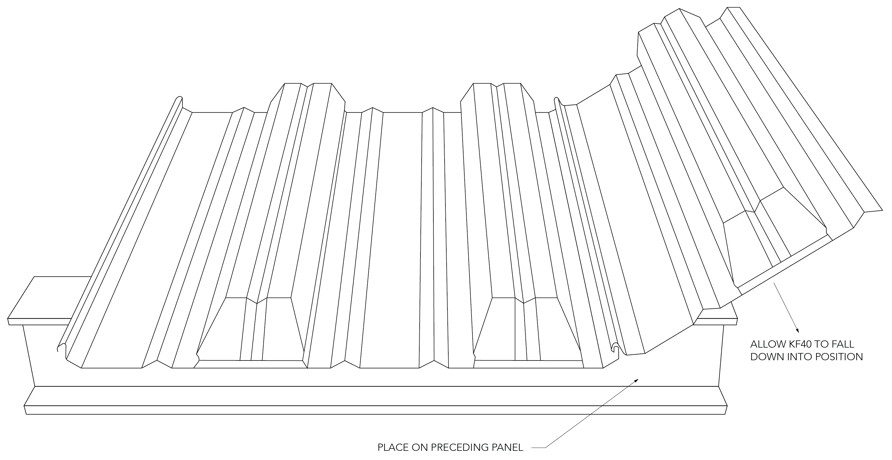
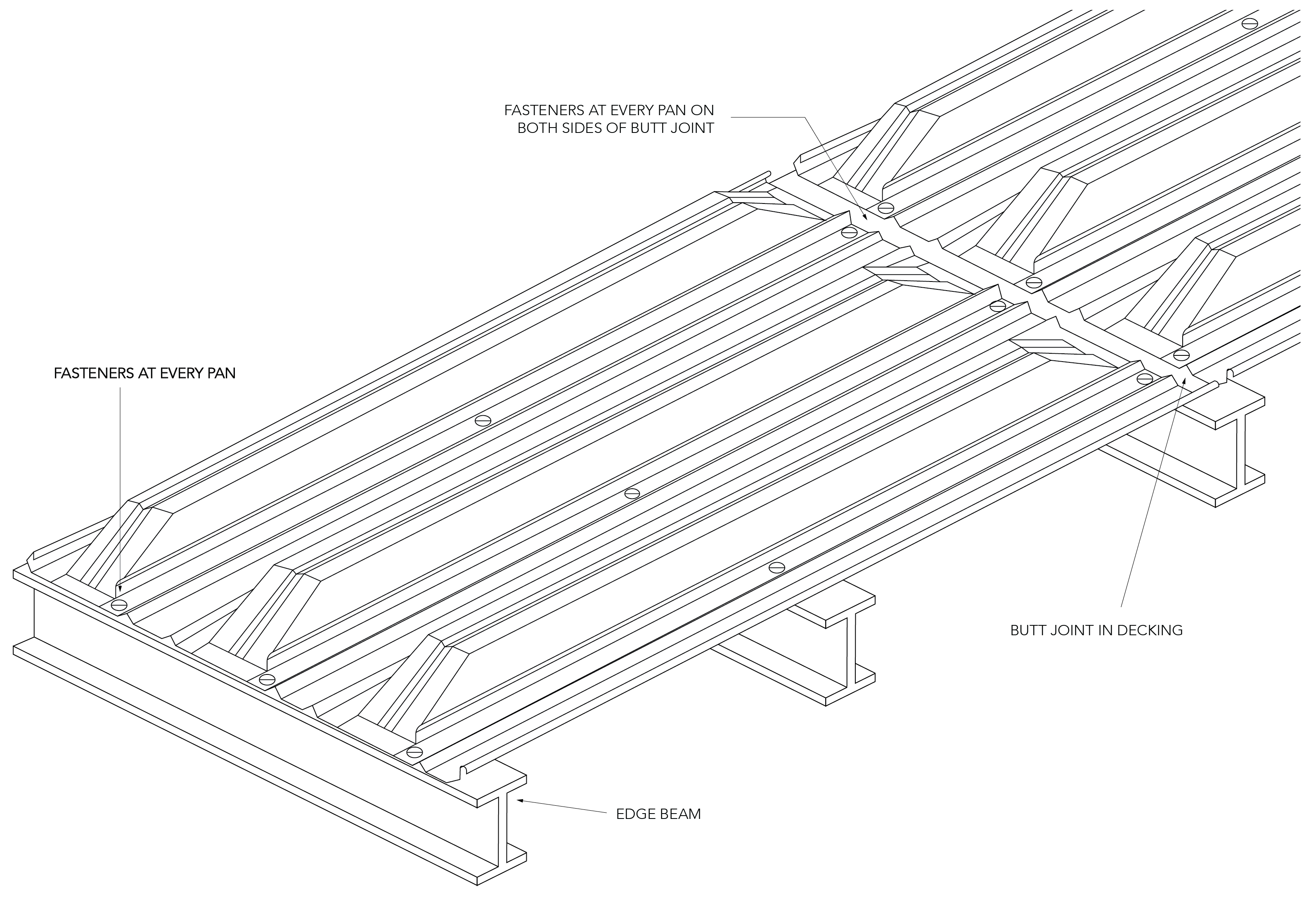
With features like SquashCut™ ends and availability in pre-cut lengths with a 600mm wide cover, KF70® significantly accelerates the installation process, making it an ideal choice for large-scale projects like TRYP by Wyndham Pulteney Street Adelaide. 


"The good thing about KingFlor® is that you can get larger spans with it, needing to use a bit less concrete, and it’s a strong profile," said a representative of Structural Systems, an Adelaide-based consulting engineering company, who were involved in the substructure and undertook inspections to ensure compliance during construction. 


The installation process of the KingFlor® KF70® system was smooth and efficient, leading to substantial savings in concrete, supporting framework, and foundation load costs.  


“We have a good relationship with Fielders and they always provide technical advice and support,” commented Samir Hanna. 


“One thing I can say about Fielders and the formwork is that the deliveries were timely and always reliable in that regard,” Daryl Crebbin said. 


Awards and Recognition

The TRYP by Wyndham Pulteney Street Adelaide project has been distinguished by multiple awards that underscore its exceptional quality, innovative approaches, and positive contributions to the community.  


Among these accolades are the Building Excellence Award for Commercial/Industrial Building, with a project cost ranging from $20 million to $50 million, given by the Master Builders Association of South Australia. This award recognises the project's outstanding construction quality and its adherence to high industry standards.  


The project also received the Professional Excellence Award 2023 for Commercial Construction, for projects valued between $25 million and $60 million, from the Australian Institute of Building. This award was granted both at the state and national levels, highlighting the project's exemplary standards in construction and design. 


By combining construction excellence with innovative design, the TRYP by Wyndham Pulteney Street Adelaide has set a new benchmark for hotels in the region, contributing significantly to the local community and the broader hospitality industry. 


Conclusion 


The TRYP by Wyndham project exemplifies the seamless integration of advanced construction technologies, notably Fielders' KingFlor® KF70® steel formwork system, to address the evolving demands of the global hospitality industry.  


This collaboration between engineers, architects, and Fielders has resulted in a development that elevates modern construction benchmarks, setting a new standard for hospitality facilities in Adelaide and further afield.  


The project, through its innovative approach and attention to detail, not only enhances Adelaide's accommodation landscape but also speaks to the potential for future developments to combine architectural innovation with practical and sustainable construction solutions. 


Art Gallery of New South Wales, NSW

ARCHITECT:
SANAA


Fielders offers bespoke solution for the Art Gallery of New South Wales

The number of innovative building products available to Australian architects, specifiers and builders these days is impressive, and continues to grow as manufacturers are constantly innovating to develop construction materials that look better, last longer and are easier and more economical to work with. 


But what if the ideal product just doesn’t exist? 


This was the case for Japanese architectural firm SANAA, who were tasked with designing the recently opened $344M AUD Sydney Gallery of Modern Art project. 

It’s a complex development that takes a bespoke construction and design approach which includes green roofs planted with Australian native species, almost 1,500m² of solar panels and of course fully curated exhibition and museum spaces. The new building also features art research and education spaces, multipurpose spaces, a gallery shop, food and beverage facilities and visitor amenities. 


The centrepiece structure was designed to complement the Art Gallery’s existing building – a 19-century structure with neoclassical façade – and presents a series of interlocking pavilions that step down towards Sydney Harbour. The buildings sit low and lightly on the land, tracing the natural topography of the land. 


A key feature of the project is the use of Fielders KingFlor®, which is used as permanent formwork for concrete slabs on multiple levels of the structure. In most cases the metal decking has been left exposed to form interior ceilings and as soffits on the building’s substantial exterior overhangs. 


When Pritzker prize-winning lead architects Kazuyo Sejima and Ryue Nichizawa, together with builders Richard Crookes Constructions evaluated the available steel decking options, they were attracted to the KingFlor® range but failed to find a profile that would meet the project’s architectural intent. So, they then approached the Fielders Design Solutions Group (DSG) for counsel.  


Introducing the DSG

The purpose of the DSG is to provide additional value to partners including architects, engineers, specifiers, builders and developers, by sharing expert advice and support to these partners throughout all stages of their projects, from early conceptualisation to completion. 


The Sydney Gallery of Modern Art development is a prime example of how the DSG can assist. Upon discovering that the client wanted a bespoke, visually driven profile for their development, Fielders’ expert team began working towards a solution. Ultimately a unique decking product KingFlor® KF100, was created exclusively for this project, which drew on the fundamentals of the existing KF70® product, but with a revised profile that delivered the architects the cleaner, smoother lines they were seeking.  


KingFlor® KF100 required a revised manufacturing process, but prior to reaching this stage, prototype products needed to be made and subjected to Fielders stringent testing program, before ultimately being trialed and verified in an independent NATA accredited laboratory.  


The DSG also assisted in a trial installation to ensure the client was completely satisfied with the appearance and functionality of KingFlor® KF100. Along with meeting its visual goals, KingFlor® KF100 delivered the functionality and cost saving benefits – that can be found across the entire KingFlor® range – to the project. 

The qualities of KingFlor®

Compared to conventional plywood formwork, the range-wide efficiencies of KingFlor® include achieving considerable time, labour and resource savings as there’s less set-up and back propping needed before pouring the slab and then removing the formwork once the concrete has cured. 


Additionally, Permanent metal deck formwork like Fielders KingFlor® stays in place after the concrete has set and has superior unpropped spans, reducing the back propping requirements and labour on site. 


The wide range of KingFlor® profiles deliver a range of benefits for end users in various building applications. The trapezoidal geometry of KF40®, KF70®, SlimDek 210® (and KF100) enable significant savings in reinforcement as well as concrete volume savings by displacing concrete where it’s not needed, reducing cost while satisfying the most stringent floor performance requirements. The cost efficiency and program advantages achieved by KingFlor® composite decking is unrivalled compared with traditional construction practices. 


And if there’s not a decking profile to suit, the DSG may even be able to design one to meet customer requirements. 


KingFlor® SlimDek 210®

KingFlor® SlimDek 210™

Features and Benefits

SlimDek 210™ Edge Detail - Parallel 2


KingFlor SlimDek 210 Section Detail

SlimDek 210®, from the Fielders KingFlor® range, is a new deep deck composite floor system. As a result of the large depth and effective cross sectional area, SlimDek 210® is capable of achieving unprecedented unpropped spans of up to 7.0 metres and propped spans up to 10.0 metres. Additional benefits of this system are realised when implemented using SlimFlor® construction, achieved by combining the SlimDek 210® profile with universal beam or universal column, or similar, with a suitable bottom flange seating plate to result in a total structural floor zone as little as 300mm.

Download the full installation manual:

 
FeatureBenefit
Unique profileConcrete savings of up to 60% when compared to alternative formwork products
Less concrete by volume Lower overall dead load of flooring, and reduced frame and foundation loads
Large unpropped spansLess propping congestion and easy access to the underside of the slab
ReLokTM FeaturesA strong mechanical interlock with the concrete slab resulting in stronger composite strength.
SlimFlor® constructionFloor system depths as low as 280mm
RF55® - Features and Benefits

Concrete Savings
SlimDek 210® effectively saves 160mm of concrete off the overall slab depth when compared to conventional concrete slabs. This represents significant savings in concrete costs, supporting framework and foundation loads.

Material Specifications
KingFlor® SlimDek 210® decking is manufactured as standard from either G550 (550MPa Yield Strength) 1.0mm Base Metal Thickness (BMT), G500 1.2mm BMT or G450 1.5mm steel. The galvanised coating thickness for all three is Z350 (minimum 350g/m2) in accordance with AS 1397-2011.

Material Properties1.0mm BMT1.2mm BMT1.5mm BMT
Mass Area – Average mass of fitted deck per plan area (kg/m2)13.6116.3420.24
Mass Linear – Mass of individual length (kg/m)8.169.812.25
Zinc Coating (g/m2) (Z350)350350350
Yield Strength (MPa)550500450
RF55® - Material Properties

Installing SlimDek 210®

Edge Infill/End Diaphragms

Galvanised steel edge diaphragms for the SlimDek 210® profile are installed prior to laying the sheets when using the SlimFlor® system. The end diaphragm aligns with the edge of the lower flange of the beam and aids in achieving the beams fire rating including fixings.

Laying SlimDek 210®

  1. Place the SlimDek 210® sheets on the asymmetric beam or beam fitted with an additional bottom flange seating plate ensuring minimum 50mm bearing is achieved. In the situation where SlimDek 210® is supported by a brick or masonry wall, a separating strip such as Malthoid is recommended.
  2. Engage subsequent sheets of SlimDek 210® by locking the larger female rib over the male rib as shown.
  3. Once engaged, the SlimDek 210® side laps are to be stitched at 500mm with 10-16 Tek screws.

Fasteners and Locations

The decking must be positively fixed to the supporting floor beam or wall, with a diaphragm, in order to avoid movement and excessive deflection during the pouring of concrete. When fixing to a steel support structure, shot fired pins or self drilling/tapping fasteners should be used with the diaphragm. Provide one fixing at each diaphragm at every sheet plus two fasteners in the top of the SlimDek 210® sheet to the diaphragm. In the case of other support systems, such as brickwork, blockwork and concrete, the SlimDek 210® must be fixed using pre drilled holes and self tapping fixings suitable for masonry or concrete. A diaphragm must be used at all supports for the Slimdek 210® sheeting to be supported on.

Temporary Propping

If temporary propping is required [refer to the quick reference tables on the back page], they should be placed at the correct centres prior to laying the SlimDek 210® sheets. Generally timber or steel bearers with a minimum dimension of 100mm x 100mm are used on vertical props. The props should be installed so as to prevent settlement during loading by wet concrete and other construction loads. Temporary props should only be removed after the slab has reached sufficient strength [at least 75% of the specified 28 day strength]. The full design load may only be applied once the slab has achieved its 28 day strength.

Reinforcement

Place all reinforcement in strict accordance with the Structural Engineers drawings and specification. The decking becomes part of the slab reinforcement with the remainder formed by a bar in each decking trough and a mesh placed near the slab top. Normally, circular plastic spacers position the bars 70mm from the base of the trough. This distance can increase to 90 or 120mm respectively when 90 or 120 minutes fire resistance is required.

Concrete Placement

The specified grade of concrete and any chemical admixtures must be in strict accordance with AS3600 and the Structural Engineers drawings and specification. The deck must be clear of any excess dirt, grease or debris as this inhibits bonding between the deck and concrete. Ensure that concrete is applied evenly over the decking surface, as mounding of the wet concrete will cause excessive local loading.

KingFlor® SlimDek 210™ Side View


KingFlor® SlimDek 210™ Fixing


KingFlor® SlimDek 210™: Typical KF210 Temp Prop


KingFlor® SlimDek 210™ Reinforcement

Single Slab Span (L) on Steel Support (mm) Formwork Deflection Limit L/130

Slab Depth (mm)
D
1.00 BMT
No. of props per span
1.20 BMT
No. of props per span
1.50 BMT
No. of props per span
010101
280535094006200105207000N/A
290520090406050102406800N/A
300505087605900100006650[111680]
3104900844056009760650011440
32047508160540095206400[11640]
3304650788053009320625011400
3404550764051509120615011160
3504450740050508920605010960
3604350720049508760590010760
3704250700048508560580010560
3804150680047508400570010400
3904050664046508240565010240
4004000652046008080555010080
SD SS FD 001 - SlimDek 210® - Table A1

Note: Span values that are equal in both tables are governed by strength

Single Slab Span (L) on Steel Support (mm) Formwork Deflection Limit L/240

Slab Depth (mm)
D
1.00 BMT
No. of props per span
1.20 BMT
No. of props per span
1.50 BMT
No. of props per span
010101
2805350994005800105206150N/A
290520090405650102406000N/A
300505087605500100005900N/A
310490084405400997605750N/A
32047508160525095205650[11640]
3304650788051509320555011400
3404550764050509120545011160
3504450740049508920535010960
3604350720049008760525010760
3704250700048008560515010560
3804150680047508400510010400
3904050664046508240500010240
4004000652046008080495010080
SD SS FD 002 - SlimDek 210® - Table A2

SlimDek Single Span, No Prop Figure

SlimDek Single Span, One Row of Props Figure

Design Assumptions

  • Concrete density: 24kN/m3
  • SlimDek 210® strength and serviceability capacities are based on full scale test results.
  • An additional concrete weight due to ponding of (0.7x deflection limit) 24.0kN/m3 has been considered for strength and serviceability limit states.
  • The spans in the above table include a minimum bearing width of 50mm on each end support.
  • Supports shall be effectively rigid and strong to support construction loads.
  • Do not cantilever SlimDek 210® over end supports.
  • The information contained in this publication is intended for guidance only. This information should only be use by a qualified structural engineer.
  • The practical limit for span to slab depth ratio is considered to be 35 for single spans, values above these limits are listed in [ ] brackets.
  • Side laps of SlimDek 210® need to be stitched by metal screws at 500mm intervals.
  • The spans in the tables are based on the condition that SlimDek 210® sheets are fixed to the end diaphagms as per Fielder’s typical details.
  • Construction live loads used for the formwork span tables are in accordance with AS/NZS 2327:2017 Appendix A Stage 2: 1.0kPa Workmen and equipment and; 2.5kPa Stacked materials (to be clearly stated on construction drawings) Stage 3: 1.0kPa Workmen and equipment or; 2.0kPa Mounding of concrete over an area of 1.6 x 1.6m2
  • The values in the tables do not consider axial loading on the sheeting.

KingFlor® KF57®

Features and Benefits


Fielders KF57® is a steel formwork solution suitable for composite concrete slabs in concrete and steel framed construction. KF57® is a light, easy to use, steel decking designed to combine with a concrete slab to produce a composite concrete slab system. KF57® incorporates an improved deck profile with deeper pan stiffeners.

Download the full installation manual:


Features and Benefits

FeatureBenefit
Permanent composite formwork systemOnce laid, KF57® becomes a permanent part of the slab, eliminating
formwork stripping
Unique profile Wide pans allow for clear access for in-oor services
Minimal propping Less propping congestion and easy access to the underside of the slab
Supplied pre-cut to length, with 300mm wide coverQuick to install
Reinforcing mesh can be laid directly on to the ribs In many applications there is no need for mesh support stools
Closed rib profile, fully embeddd in concrete slab Major reduction in fire reinforcement
KF57® - Features and Benefits

KF57® - Material Specifications


KF57 is manufactured from G550 (550 MPa Yield Stress) steel with a Base Metal Thickness (BMT) of 0.75mm and 1.00mm. The galvanised coating thickness is a Z350 (350 g/m2) in accordance with AS 1397:2001.

Material Properties0.75 BMT1.00 BMT
Mass Area – Average mass of fitted deck per plan area (kg/m2)9.9713.10
Mass Linear – Mass of individual length (kg/m)2.993.93
Zinc Coating (g/m2) (Z350)350350
Yield Strength (MPa)550550
Note:
KF57® is also available with Fielders patented Re-Lok corner embossments for superior composite slab performance. Please check with your local Fielders representative for details.

KF57® Formwork/Slab Span Tables Single Span

Single Slab Span (L) on Steel support Formwork deflection limits L/130 and L/240

L/130 L/130 L/240 L/240
Slab
Depth
(mm)
0.75 BMT
Number of props per span
1.0 BMT
Number of props per span
0.75 BMT
Number of props per span
1.0 BMT
Number of props per span
0123012301230123
902550[5950][9000][12050]3100[7800][10900][14850]2350[6000][8350][11400]2600[6600][9200][12550]
100
2450[5800][8750][11700]3000[7650][10650][14450]2300[5850][8100][11050]2500[6400][8900][12150]
1102400[5650][8550][11400]2900[7450][10350][14100]2200[5700][7900][10750]2450[6250][8650][11800]
1202350[5500][8350][11150]2850[7250][10100][13800]2150[5550][7700][10450]2400[6100][8450][11500]
1302300[5350][8150][10900]2800[7050][9900][13500]2100[5400][7500][10200]2300[5950][8250][11250]
1402250[5250][7950][10650]2750[6900][9700][13200]2050[5300][7350][10000]2250[5800][8050][11000]
15022005100[7750][10400]2700[6750][9550][12950]20005150[7200][9800]2200[5700][7900][10800]
16021505000[7600][10150]2650[6600][9350][12750]20005050[7050][9600]21505600[7750][10550]
17021004900[7450][9950]2600[6450][9200][12500]19504950[6900][9400]21505500[7600][10350]
18021004850[7300][9800]2550[6350][9000][12300]19004900[6800][9250]21005400[7450][10150]
19020504750[7200][9650]25006250[8900][12100]19004800[6700][9100]20505300[7350][10000]
20020004650[7100][9450]24506100[8750][11900]185047006550[8950]20505200[7250][9850]
210200046006950[9300]24506000[8600][11750]180046506450[8800]200051507100[9700]
220195045006850[9150]24005900[8500][11600]180045506400[8700]195050507000[9550]
230190044506750[9000]23505800[8400][11400]175045006300[8550]195050006900[9450]
240190043506600[8850]235057008300[11300]175044006200[8450]190049006850[9300]
2501850430065008700230056508200[11150]1700435061008350190048506750[9200]
2601850425064008550225055508100[11000]17004300605082501850480066509050
2801800415062008300220054007900[10800]16504150590080501800470065008850
30017504000605080502150525077501050016004050575078501750460063508650
32017003900590078502100510076001020016003950565077001750450062508500
3401650380057507650210049507450995015503850555075501700440061008300
3603750560075007500205048507300970015503750545074001650430060008150
3801600365055007350200047507100950015003650535073001650425059008000
4001550360054007200200046506950930015003600525072001650415058007900
Notes:
1. Concrete density: 24kN/m3.
2. KF57® strength and serviceability capacities are based on full scale test results.
3. An additional concrete weight due to ponding of (0.7x deflection limit) 24.0kN/m3 has been considered for Strength and serviceability limit states.
4. The spans in the above table include a minimum bearing width of 50mm on each end support.
5. Supports shall be effectively rigid and strong to support construction loads.
6. The information contained in this publication is intended for guidance only. This information should only be use by a qualified structural engineer.
7. The practical limit for span to slab depth ratio is considered to be 35 for single spans, 40 for continuous spans. Values above these limits are listed in [ ] brackets.
8. The spans in the tables are based on the condition that KF57® sheets are fully restrained in the direction perpendicular to the sheet span.
9. Tables are based on the following maximum construction loads:
− Workmen and equipment: 1kN/m2
− Mounting of concrete: 2kN/m2 over an area of 1.6m x 1.6m and zero on the rest of the area
− Stacking of material on KF57® before placement of concrete: 1kN/m2
− The table does not consider axial loads on the product
− Allowance for weight of reinforcement as well as the effect of ponding is included

KF57® Formwork/Slab Span Tables Continuous Span

Continuous: 3 spans (L) on steel support Formwork deflection limits L/130 and L/240

L/130 L/130 L/240 L/240
Slab
Depth
(mm)
0.75 BMT
Number of props per span
1.0 BMT
Number of props per span
0.75 BMT
Number of props per span
1.0 BMT
Number of props per span
0123012301230123
903000[6000][9000][12050]3600[7400][11100][14800]2750[5650][8500][11350]3050[6250][9350][12450]
100
2900[5850][8750][11700]3550[7200][10800][14400]2700[5500][8250][11000]2950[6050][9050][12100]
1102850[5700][8550][11400]3450[7000][10550][14050]2600[5350][8050][10700]2850[5850][8800][11750]
1202750[5550][8350][11150]3350[6850][10300][13700]2550[5200][7800][10400]2800[5700][8600][11450]
1302700[5450][8150][10900]3300[6700][10050][13400]25005100[7600][10150]2750[5600][8400][11200]
14026505300[8000][10650]3200[6550][9850][13150]24504950[7450][9950]26505450[8200][10950]
15025505200[7750][10400]3150[6450][9700][12900]23504850[7300][9750]26005350[8050][10750]
16025005050[7600][10150]31006350[9500][12700]23504750[7150][9550]25505250[7850][10500]
17024504950[7450][9950]30506200[9350][12450]23004650[7000][9350]25005150[7700][10300]
18024504900[7350][9800]30006100[9200][12250]225046006900[9200]24505050[7600][10150]
190240048007200[9650]29506000[9050][12050]220045006800[9050]245049507450[9950]
200235047007100[9450]29005900[8900][11850]220044506700[8900]240049007350[9800]
210230046506950[9300]28505850[8750][11700]215044006550[8750]235048007250[9650]
220225045506850[9150]280057508650[11550]2100430065008650230047507150[9500]
2302250450067509000280057008550[11400]2050425064008500230047007050[9400]
2402200440066008850275056008450[11250]20504200630084002250460069509250
2502150435065008700270055508300[11100]20004150620083002250455068509150
2602100425064008550270055008250[11000]20004100615082002200450067509050
28020504150620083002600535080501075019504000600080002150440066008800
30020004000605080502550525078501050019003900585078002100430064508650
32019503900590078502500510076501020018503800575076502050420063508450
3401900380057507650245049507450995018503750560075002000415062008300
3603750560075007500240048507300970018003650550073502000405061008150
3801800365055007350235047507100950017503600545072501950400060008000
4001800360054007200230046506950930017503550535071501900390059007850
Notes:
1. Concrete density: 24kN/m3.
2. KF57® strength and serviceability capacities are based on full scale test results.
3. An additional concrete weight due to ponding of (0.7x deflection limit) 24.0kN/m3 has been considered for Strength and serviceability limit states.
4. The spans in the above table include a minimum bearing width of 50mm on each end support.
5. Supports shall be effectively rigid and strong to support construction loads.
6. The information contained in this publication is intended for guidance only. This information should only be use by a qualified structural engineer.
7. The practical limit for span to slab depth ratio is considered to be 35 for single spans, 40 for continuous spans. Values above these limits are listed in [ ] brackets.
8. The spans in the tables are based on the condition that KF57® sheets are fully restrained in the direction perpendicular to the sheet span.
9. Tables are based on the following maximum construction loads:
− Workmen and equipment: 1kN/m2
− Mounting of concrete: 2kN/m2 over an area of 1.6m x 1.6m and zero on the rest of the area
− Stacking of material on KF57® before placement of concrete: 1kN/m2
− The table does not consider axial loads on the product
− Allowance for weight of reinforcement as well as the effect of ponding is included

KF57® Temporary Propping Tables

KF57® Frame Propping - 1200mm Frame Size Maximum Spans (mm) for Deflection L/240

Dcs (mm) 1 Frame 2 Frame
0.75 BMT 1.00 BMT 0.75 BMT 1.00 BMT
100[5,300][5,700][8,550][9,150]
110[5,200][5,600][8,400][9,000]
120[5,100][5,500][8,250][8,850]
130[5,000][5,400][8,100][8,700]
1404900[5,300][7,950][8,550]
15048005200[7,800][8,400]
16047005100[7,650][8,250]
17047005000[7,650][8,100]
18046005000[7,500][8,100]
19045004900[7,350][7,950]
20045004800[7,350][7,800]
210440048007200[7,800]
2204400470072007650
2304300470070507650
2404300460070507500
2504300460070507500
Notes:
1. Concrete density: 24kN/m3.
2. KF57® strength and serviceability capacities are based on full scale test results.
3. An additional concrete weight due to ponding of (0.7x deflection limit) 24.0kN/m3 has been considered for Strength and serviceability limit states.
4. The spans in the above table include a minimum bearing width of 50mm on each end support.
5. Supports shall be effectively rigid and strong to support construction loads.
6. The information contained in this publication is intended for guidance only. This information should only be use by a qualified structural engineer.
7. The practical limit for span to slab depth ratio is considered to be 35 for single spans, 40 for continuous spans. Values above these limits are listed in [ ] brackets.
8. The spans in the tables are based on the condition that KF57® sheets are fully restrained in the direction perpendicular to the sheet span.
9. Tables are based on the following maximum construction loads:
− Workmen and equipment: 1kN/m2
− Mounting of concrete: 2kN/m2 over an area of 1.6m x 1.6m and zero on the rest of the area
− Stacking of material on KF57® before placement of concrete: 1kN/m2
− The table does not consider axial loads on the product
− Allowance for weight of reinforcement as well as the effect of ponding is included

KF57® Frame Propping - 1500mm Frame Size Maximum Spans (mm) for Deflection L/240

Dcs (mm) 1 Frame 2 Frame
0.75 BMT 1.00 BMT 0.75 BMT 1.00 BMT
100[5,600][6,000][9,150][9,750]
110[5,500][5,900][9,000][9,600]
120[5,400][5,800][8,850][9,450]
130[5,300][5,700][8,700][9,300]
140[5,200][5,600][8,550][9,150]
1505100[5,500][8,400][9,000]
16050005400[8,250][8,850]
17050005300[8,250][8,700]
18049005300[8,100][8,700]
19048005200[7,950][8,550]
20048005100[7,950][8,400]
21047005100[7,800][8,400]
22047005000[7,800][8,250]
230460050007650[8,250]
2404600490076508100
2504600490076508100
Notes:
1. Concrete density: 24kN/m3.
2. KF57® strength and serviceability capacities are based on full scale test results.
3. An additional concrete weight due to ponding of (0.7x deflection limit) 24.0kN/m3 has been considered for Strength and serviceability limit states.
4. The spans in the above table include a minimum bearing width of 50mm on each end support.
5. Supports shall be effectively rigid and strong to support construction loads.
6. The information contained in this publication is intended for guidance only. This information should only be use by a qualified structural engineer.
7. The practical limit for span to slab depth ratio is considered to be 35 for single spans, 40 for continuous spans. Values above these limits are listed in [ ] brackets.
8. The spans in the tables are based on the condition that KF57® sheets are fully restrained in the direction perpendicular to the sheet span.
9. Tables are based on the following maximum construction loads:
− Workmen and equipment: 1kN/m2
− Mounting of concrete: 2kN/m2 over an area of 1.6m x 1.6m and zero on the rest of the area
− Stacking of material on KF57® before placement of concrete: 1kN/m2
− The table does not consider axial loads on the product
− Allowance for weight of reinforcement as well as the effect of ponding is included

Installing Fielders KF57®

Temporary Propping
If temporary propping is required (refer to the temporary propping tables), props should be placed at the correct centres prior to laying the KF57® sheets. Generally, timber or steel bearers with a minimum dimension of 75mm x 75mm are used on vertical props. The props should be installed so as to prevent settlement during loading by wet concrete and other construction loads. Wide ply strips, of 300mm wide, may be positioned above the header bearers to assist in dispersing the load and minimise any local deformation of the decking due to the headers. Temporary props should only be removed after the slab has reached sufficient strength (at least 75% of the specified 28-day strength). The full design load may only be applied once the slab has achieved 28-day strength.

Edge-form
Galvanised steel edge-forms can be used for the retention of wet concrete to the correct level at the decked floor perimeters. KF57® edge-form is usually shot-fired to the steel support structure or to the KF57® deck and the top of the edge-form is connected back to the decking with restraint straps at approximately 600mm centres using either pop-rivets or self-drilling screws.


Fasteners and Locations
The decking must be secured to the supporting structure in order to avoid movement and excessive deflection during the pouring of concrete. When fixing to a steel support structure, shot fired pins or self-drilling/tapping fasteners should be used. Provide one fastener in each pan at every support. In the case of other support systems, such as brickwork, block work and concrete, the KF57® sheets must be temporarily held in place against wind and other effects until the concrete is poured.


Reinforcement
Place all reinforcement in strict accordance with the structural engineer’s drawings and specification.

Concrete Placement
The specified grade of concrete and any chemical admixtures must be in strict accordance with AS 3600:2018 and the structural engineer’s drawings and specification. The deck must be clear of any excess dirt, grease or debris as this inhibits bonding between the deck and concrete. Ensure that concrete is applied evenly over the decking surface, as mounding of the wet concrete will cause excessive local loading.


Laying KF57®
1. Place the KF57® sheet over the supports ensuring a minimum end bearing of 50mm. If supporting on a brick or masonry wall, provide a separating strip such as malthoid.
2. Engage subsequent sheets of KF57® by locking the larger female rib over the male rib as shown in the diagram below.


KingFlor® RF55®

Features and Benefits


Fielders RF55® is a traditional flat pan or ‘re-entrant’ profile that provides unmatched performance in suspended concrete slabs. RF55® is used in both concrete and steel frame construction and utilises patented technology to achieve superior spanning capabilities, less deflection and greater composite strength than similar re-entrant profiles. RF55® comes complete with a range of accessories allowing for easy suspension of ceilings and services.

Download the full installation manual:

 
FeatureBenefit
Unique profileConcrete savings of up to 60% when compared to alternative formwork products
Less concrete by volume Lower overall dead load of flooring, and reduced frame and foundation loads
Large unpropped spansLess propping congestion and easy access to the underside of the slab
ReLokTM FeaturesA strong mechanical interlock with the concrete slab resulting in stronger composite strength.
SlimFlor® constructionFloor system depths as low as 280mm
RF55® - Features and Benefits

RF55® Material Specifications

RF55® is manufactured from G550 (550 MPa Yield Stress) steel with a Base Metal Thickness (BMT) of 0.60mm, 0.75mm, and 1.00mm. The thicknesses of 0.90mm and 1.20mm BMT are also available on request. The galvanised coating thickness is a Z350 (350 g/m2) in accordance with AS 1397:2001. RF55® is available in two sheet widths. The traditional 600mm wide cover, 3-PAN, and the easy to handle, 400mm wide cover, 2-PAN. The RF55®-2P is equivalent in all aspects technically to the RF55®-3P. Similarly, the recommendations for RF55® in construction also apply to both RF55®-3P and RF55®-2P. Please check with your local branch as to which version applies in your state.

Material Properties1.0mm BMT1.2mm BMT1.5mm BMT
Mass Area – Average mass of fitted deck per plan area (kg/m2)13.6116.3420.24
Mass Linear – Mass of individual length (kg/m)8.169.812.25
Zinc Coating (g/m2) (Z350)350350350
Yield Strength (MPa)550500450
RF55® - Material Properties

RF55® Formwork/Slab Span Tables Single Span

RF55® Formwork/Slab Span Tables Continuous Span

Slab
Depth
(mm)
0.6 BMT
Number of props per span
0.75 BMT
Number of props per span
0.9 BMT
Number of props per span
1.0 BMT
Number of props per span
0123012301230123
902400(5400) (8150)(10850) 3350
(6800) (10200) (13600)(3700) (7500) (11300) (15050) (3800) (7800) (11700) (15600)
100
2350 (5250)(7900) (10550) 3250(6600)(9900) (13200) 3600 (7300) (11000) (14650) 3700 (7600) (11400) (15200)
1102250(5150) (7700)(10300) 3200(6400)(9650) (12850) 3500(7150) (10700) (14300) 3650(7400) (11100) (14800)
1202200(5000) (7500) (10000) 3100(6250) (9350) (12500) 3400 (6950) (104500 (13950) 3550(7200) (10850) (14450)
1302150(4900)(7350)(9800) 3000(6100) (9150) (12200) 3350(6800)(10200) (13600) 3450(7050) (10600) (14150)
14021004750(7150) (9550) 2950(5950)(8900) (11900)3250(6650) (10000) (13350) 3400(6900) (10400) (13850)
15020504650(7000) (9350) 29005800(8700) (11650) 3200(6500) (9800) (13050) 3300(6800) (10150) (13550)
1602050 4550(6850) (9150) 28505700(8550) (11400) 31506400 (9650) (12850) 3250(6650) (10000) (13300)
1702000 4500 (6750) (9000) 27505600(8400) (11200) 31006300(9450) (12600) 32006550 (9800) (13100)
1801950 4400(6600) (8800) 27005500(8250) (11000)30506200(9300) (12400) 31506450(9650) (12900)
1901900 4300(6600) (8800) 26505350
(8050) (10750) 30006100(9150) (12200) 31006350(9500)(12700)
2001900 4250 6350 (8500) 260052507900(10550) 29506000(9000) (12000) 30506250(9350) (12500)
2101850 4150 6250 (8350) 255051507750(10350) 29005900(8850) (11800) 30006150(9200) (12300)
2201800 4100 6150(8200) 250051007650(10200) 285058008750 (11650) 29506050(9050) (12100)
2301800 40006050 (8050) 250050007500(10000) 280057508600(11500) 290059508950 (11950)
2401750 3950 5950 7950 245049007400(9850) 275056508500(11350) 290059008850 (11800)
2501750 3900 5850 7800 2400485072509700275056008400(11200) 285058008700 (11650)
26017003850580077002350475071509550270055508300(11100) 280057508600(11500)
2801650 3750 5600 7500230046006950925026505400810010800275056008450(11250)
3001650 3650 55007350 225045006750900025505200785010450 26505500825011000
3201600 360054007200 215043506550875025005050760010150 26005350800010700
3401550 3500 5250 70002100425064008500245049507400990025505200780010450
360150034005150 68502050415062008300240048007250965025005100765010200
3801550 3350 50006700200040506050810023504700705094502400495074509950
4001450 3250 4900650019503950595079002300460069009250 2350485073009750
Notes:
1. Concrete density: 24kN/m3.
2. RF55® strength and serviceability capacities are based on full scale test results.
3. An additional concrete weight due to ponding of (0.7x deflection limit) 24.0kN/m3
has been considered for Strength and serviceability limit states.
4. The spans in the above table include a minimum bearing width of 50mm on each end support.
5. Supports shall be effectively rigid and strong to support construction loads.
6. The information contained in this publication is intended for guidance only.
This information should only be use by a qualified structural engineer.
7. The practical limit for span to slab depth ratio is considered to be 35 for single spans, 40 for continuous spans. Values above these limits are listed in [ ] brackets.
8. The spans in the tables are based on the condition that RF55® sheets are fully restrained
in the direction perpendicular to the sheet span.
9. Tables are based on the following maximum construction loads: − Workmen and equipment: 1kN/m2
− Mounting of concrete: 2kN/m2 over an area of 1.6m x 1.6m and zero on the rest of the area
− Stacking of material on RF55® before placement of concrete: 1kN/m2
− The table does not consider axial loads on the product
− Allowance for weight of reinforcement as well as the effect of ponding is included

RF55® Formwork/Slab Span Tables Continuous Span

Single Slab Span (L) on Steel support Formwork deflection limits L/130

Slab
Depth
(mm)
0.6 BMT
Number of props per span
0.75 BMT
Number of props per span
0.9 BMT
Number of props per span
1.0 BMT
Number of props per span
0123012301230123
902400(5400)(8150) (10850) 2700(6700) (10200) (13600) 2850(7900) (11100) (15100) 2950(8150) (11550) (15650)
100
2350(5250)(7900) (10550) 2600(6500) (9900) (13200) 2800(7650) (10800) (14700) 2850(8000) (11200) (15250)
1102250(5150) (7700) (10300) 2550(6350) (9600) (12850) 2700(7450) (10550) (14350) 2800(7850) (10900) (14850)
1202200(5000)(7500) (10000) 2500(6200) (9350) (12500) 2650(7250) (10300) (14000) 2750(7650) (10700) (14550)
1302150(4900)(7350) (9800) 2450(6000) (9150) (12200) 2550(7050) (10050) (13700) 2650(7450) (10450) (14200)
14021004750(7150) (9550) 2400(5900) (8900) (11900) 2500(6900) (9850) (13400) 2600(7250) (10200) (13900)
15020504650(7000) (9350) 2350(5750) (8700) (11650) 2450(6700) (9650) (13100) 2550(7100) (10000) (13650)
16020504550(6850) (9150) 2300(5650) (8500) (11400) 2400(6600) (9450) (12900) 2500(6950) (9800) (13400)
17020004500(6750) (9000)22505550 (8400) (11200) 2400(6450) (9300) (12650) 2450(6800) (9650) (13150)
18019504400(6600) (8800) 22005400(8200) (11000) 2350(6350) (9150) (12450) 2400(6650) (9500) (12950)
190190043006500 (8650) 21505300 (8050) (10750) 23006200 (9000) (12250) 24006650(9350) (12750)
200190042506350 (8500) 21005200(7900) (10600) 22506100(8850) (12050) 23506450 (9200) (12550)
210185041506250 (8350) 21005100(7750) (10350) 22005950(8700) (11850) 23006300 (9050) (12350)
220180041006150 (8200) 205050507600 (10200)22005850(8600) (11700) 22506200(8950) (12200)
230180040006050 (8050) 205049507500(10000)21505750(8500) (11550) 22506100(8800) (12000)
240175039505950 7950 200048507400(9850) 215057008350 (11400) 22006000(8700) (11850)
250175039005850 7800200048007250(9700) 210056008250(11250) 215059008600 (11700)
2601700385058007700195047507150(9550)205055508150(11150) 215058008500 (11550)
28016503750560075001900460069509250 205053508000(10800) 210056508300(11300)
3001650365055007350 180045006750900020005200775010450 205055008050(11050)
32016003600540072001750435065508750 19505050755010150 20005350785010750
340155035005250 70001700425064008500190049507350
990020005250765010500
360155034005150 6850 1700415062008300 1850480072009650 19505100750010200
38015003350500067001650405060508100 180047007050945018505000730010000
400145032504900650016003950595079001750460069009250 1850485071509750
Notes:
1. Concrete density: 24kN/m3.
2. RF55® strength and serviceability capacities are based on full scale test results.
3. An additional concrete weight due to ponding of (0.7x deflection limit) 24.0kN/m3
has been considered for Strength and serviceability limit states.
4. The spans in the above table include a minimum bearing width of 50mm on each end support.
5. Supports shall be effectively rigid and strong to support construction loads.
6. The information contained in this publication is intended for guidance only.
This information should only be use by a qualified structural engineer.
7. The practical limit for span to slab depth ratio is considered to be 35 for single spans, 40 for continuous spans. Values above these limits are listed in [ ] brackets.
8. The spans in the tables are based on the condition that RF55® sheets are fully restrained
in the direction perpendicular to the sheet span.
9. Tables are based on the following maximum construction loads: − Workmen and equipment: 1kN/m2
− Mounting of concrete: 2kN/m2 over an area of 1.6m x 1.6m and zero on the rest of the area
− Stacking of material on RF55® before placement of concrete: 1kN/m2
− The table does not consider axial loads on the product
− Allowance for weight of reinforcement as well as the effect of ponding is included

RF55® Formwork/Slab Span Tables Continuous Span

Continuous : 3 Spans (L) on steel support - Formwork deflection limits L/240

Slab
Depth
(mm)
0.6 BMT
Number of props per span
0.75 BMT
Number of props per span
0.9 BMT
Number of props per span
1.0 BMT
Number of props per span
0123012301230123
902650(5450) (8200) (10900) 2900(5950) [8950][11900]3100[6350][9550][12750]3250[6600][9900][13200]
100
2600(5250) (7900) (10550) 2800(5750) [8650][11550]3000[6150][9250][12350]3150[6400][9600][12800]
1102500(5100) (7650) (10250) 2750(5600) [8400][11200]2950[5950][8950][11950]3050[6200][9350][12450]
1202450(4950) (7450) (9950) 2650(5450) [8200][10900]2850[5800][8750][11650]2950[6050][9050][12100]
13023504850 (7250) (9700)2600(5300) [8000][10650]2800[5650][8500][11350]2900[5900][8850][11800]
14022504650(7000) (9350) 25505200[7800][10400]27005550[8350][11100]2800[5750][8650][11550]
15022004500(6800) (9050) 25005050[7600][10150]26505450[8150][10900]27505650[8500][11300]
16021504400(6600) (8800) 24004950[7450][9950]26005300[8000][10650]27005500[8300][11050]
170205042506400(8550) 23504850[7300][9750]25505200[7800][10400]26005400[8100][10800]
180200041506200(8300)230047507100[9500]24505050[7600][10150]25505250[7900][10550]
190195040506050(8100) 225046506950[9250]240049507450[9900]25005150[7750][10300]
2001900395059007900220045006800[9050]235048507300[9700]245050507550[10100]
2101850385057507700215044506650[8850]230047507150[9500]240049507400[9900]
22018503750565075502100435065008700225046507000[9350]235048507300[9750]
230180037005500740020504250640085002250460068509150230047507150[9550]
2401750360054507250200041506250835022004500675090002300470070509400
2501700355053507100200041006150820021504400665088502250460069009250
2601700350052507100195040006050805021004350655087002200455068009100
2801600335050506750190039005850780020504200635084502150440066008850
3001550325048506500185037505650755020004100615082002100430064508600
3201500315047006300180036505500735019504000600080002050415062508350
3401450305045506100175036005350720019003900585078002000405061008150
3601450295044505950170035005250700018503800570076001950395059507950
3801400290043505800165034005100680018003700555074501900390058507800
4001350285043005750160033005000665017503650545073001850380057007650
Notes:
Concrete density: 24kN/m3.
2. RF55® strength and serviceability capacities are based on full scale test results.
3. An additional concrete weight due to ponding of (0.7x deflection limit) 24.0kN/m3
has been considered for Strength and serviceability limit states.
4. The spans in the above table include a minimum bearing width of 50mm on each end support.
5. Supports shall be effectively rigid and strong to support construction loads.
6. The information contained in this publication is intended for guidance only.
This information should only be use by a qualified structural engineer.
7. The practical limit for span to slab depth ratio is considered to be 35 for single spans, 40 for continuous spans. Values above these limits are listed in [ ] brackets.
8. The spans in the tables are based on the condition that RF55® sheets are fully restrained
in the direction perpendicular to the sheet span.
9. Tables are based on the following maximum construction loads: − Workmen and equipment: 1kN/m2
− Mounting of concrete: 2kN/m2 over an area of 1.6m x 1.6m and zero on the rest of the area
− Stacking of material on RF55® before placement of concrete: 1kN/m2
− The table does not consider axial loads on the product
− Allowance for weight of reinforcement as well as the effect of ponding is included

Installing Fielders RF55®

Temporary Propping
If temporary propping is required (refer to the temporary propping tables), props should be placed at the correct centres prior to laying the RF55® sheets. Generally, timber or steel bearers with a minimum dimension of 75mm x 75mm are used on vertical props. The props should be installed so as to prevent settlement during loading by wet concrete and other construction loads. 300mm wide ply strips, may be positioned above the header bearers to assist in dispersing the load and minimise any local deformation of the decking due to the headers. Temporary props should only be removed after the slab has reached sufficient strength (at least 75% of the specified 28-day strength). The full design load may only be applied once the slab has achieved 28-day strength.


Fasteners and Locations
The decking must be positively fixed to the supporting structure in order to avoid movement and excessive deflection during the pouring of concrete. When fixing to a steel support structure, shot fired pins or self- drilling/tapping fasteners should be used. Provide one fastener in each pan at every support. In the case of other support systems, such as brickwork, block work and concrete, the RF55® sheets must be temporarily held in place against wind and other effects until the concrete is poured.

Edge-form
Galvanised steel edge-forms can be used for the retention of wet concrete to the correct level at the decked floor perimeters. Edge-form is usually shot-fired to the steel support structure or to the RF55® deck and the top of the trim is connected back to the decking with restraint straps at approximately 600mm centres using either pop-rivets or self-drilling screws.


Reinforcement
Place all reinforcement in strict accordance with the structural engineer’s drawings and specification.

Concrete placement
The specified grade of concrete and any chemical admixtures must be in strict accordance with AS 3600:2018 and the structural engineer’s drawings and specification. The deck must be clear of any excess dirt, grease or debris as this inhibits bonding between the deck and concrete. Ensure that concrete is applied evenly over the decking surface, as mounding of the wet concrete will cause excessive local loading.


Laying RF55®
1. Place the RF55® sheet over the supports ensuring a minimum end bearing of 50mm. If supporting on a brick or masonry wall, provide a separating strip such as malthoid.


2. Tap the female rib with a hammer at a 45° angle to lock it into place.


KingFlor® Designer Suite

KINGFLOR® Designer Suite - Register and Download Now

The KingFlor® Designer Suite software produces designs in accordance with the following versions of Australian Standards, as applicable at the time of the software’s development in 2017:

  • AS 3600:2009 - Concrete Structures
  • AS/NZS 2327:2017 - Composite Structures – Composite steel-concrete construction in buildings

Designs produced using the KingFlor® Designer Suite software do not comply with subsequent revisions to these Australian Standards (including AS/NZS 2327:2017 Amd 1: 2020 and AS 3600:2018 Amd 1 & 2: 2021) or any Australian Standards released after 2017.

To support engineers with checking their design’s compliance with current Australian Standards, Fielders has prepared the KingFlor® Formwork and Composite Slab Design Guide – Using RAPT Software, which outlines a practical workflow using relevant Fielders technical literature, together with a third-party analysis and design software known as “RAPT”. The guide is accessible here: [Fielders KingFlor formwork and Composite Slab Design Guide using RAPT Software].

To avoid doubt, KingFlor® flooring and decking products are manufactured and tested to comply with applicable laws, regulations and Australian Standards, as detailed in Fielders’ KingFlor® National Construction Code Compliance Bulletin (Jan 2024), accessible here: [Fielders NCC Compliance Bulletin Kingflor ].


Features to the KingSlab software include:

  • Ability to design continuous slabs with the entire range of Fielders KingFlor® range, including SlimDek 210® with the flexibility to suit your project needs.
  • Full 3D graphic display of the reinforced composite slab
  • Optimisation of reinforcement design by utilising the composite action of the steel decking profiles
  • Fire design assessment of composite slabs
  • Ability to design the formwork stage of construction

Features to the KingBeam software include:

  • Ability to design primary or secondary composite downstand beams including shear studs with any KingFlor® profile bearing on the top flange
  • Ability to design SlimFlor® using fully customisable 3 Plate Asymmetric Steel Beams (ASB) with SlimDek 210® bearing on the bottom flange
  • Design SlimFlor® beams using hot rolled UC sections with welded bottom plate


Access the software

KingFlor® Designer Suite is available for download now.

About KingFlor®

KingFlor® Designer Suite

The KingFlor® Designer Suite software produces designs in accordance with the following versions of Australian Standards, as applicable at the time of the software’s development in 2017:

  • AS 3600:2009 - Concrete Structures
  • AS/NZS 2327:2017 - Composite Structures – Composite steel-concrete construction in buildings

Designs produced using the KingFlor® Designer Suite software do not comply with subsequent revisions to these Australian Standards (including AS/NZS 2327:2017 Amd 1: 2020 and AS 3600:2018 Amd 1 & 2: 2021) or any Australian Standards released after 2017.

To support engineers with checking their design’s compliance with current Australian Standards, Fielders has prepared the KingFlor® Formwork and Composite Slab Design Guide – Using RAPT Software, which outlines a practical workflow using relevant Fielders technical literature, together with a third-party analysis and design software known as “RAPT”. The guide is accessible here: [Fielders KingFlor formwork and Composite Slab Design Guide using RAPT Software].

To avoid doubt, KingFlor® flooring and decking products are manufactured and tested to comply with applicable laws, regulations and Australian Standards, as detailed in Fielders’ KingFlor® National Construction Code Compliance Bulletin (Jan 2024), accessible here: [Fielders NCC Compliance Bulletin Kingflor ].

Access the software

KingFlor® Designer Suite is available for download now.


KingFlor® KF40®

Fielders KF40® Ikea

About KF40®

Fielders KF40® is a revolutionary steel formwork solution suitable for concrete slabs in all types of construction. KF40® combines the performance of a traditional flat pan profile with the unmatched economy and concrete saving of a trapezoidal deck.

KF40® Slab Cut Away 160519


KF40® Features and Benefits

FeatureBenefit
SquashCut™ endsNo end caps needed. Also provides rigid and secure platform during construction.
Unique off-set lapEnables shear studs to be placed centrally in the pan in the most optimal position.
Unique profileConcrete savings up to 40kg/m2 (16mm off slab depth).
Lower 40mm heightSuitable for post-tensioning ducts.
Wide 742mm coverEconomical deck.
Strong re-entrant featuresKF40® has been specifically designed to provide a strong and reliable shear bond performance giving strong composite slabs.

Concrete Savings

KF40® saves the equivalent of 16mm of concrete from the overall slab depth by concrete volume when compared to conventional concrete slabs. This represents a significant saving in concrete costs, supporting framework and foundation loads.

KF40® Material Specifications

KF40® is manufactured from G550 (550 MPa Yield Stress) steel in a 3 pan profile with a Base Metal Thickness (BMT) of 0.75mm and 1.00mm. The galvanised coating thickness is a Z350 (350 g/m2) in accordance with AS 1397:2001.

Material Properties0.75 BMT1.00 BMT
Mass Area – Average mass of 3-PAN deck per plan area (kg/m2)8.3510.97
Mass Linear – Mass of individual 3-PAN length (kg/m)6.198.14
Zinc Coating (g/m2) (Z350)350350
Yield Strength (MPa)550550

KF40® 3-Pan Formwork/Slab Span Tables - Simple Span

Single Slab Span (L) on Steel support: Formwork deflection limits L/130

Slab
Depth
(mm)
0.75 BMT
Number of props per span
1.0 BMT
Number of props per span
012012
902250[5900][8250]2450[6450][9000]
1002150[5700][8000]2350[6250][8700]
1102100[5550][7750]2300[6100][8500]
1202050[5400][7550]2250[5950][8250]
1302000[5300][7350]2150[5800][8050]
1401950[5150][7200]2100[5650][7850]
15019005000[7000]2050[5550][7700]
16018504900[6850]20505450[7550]
17018004800[6750]20005300[7400]
18017504700[6600]19505200[7250]
19017004650650019005150[7150]
200165045506400190050507000
210165044506300185049506900
220160044006200180049006800
230160043006100175048506700
240155042506000175048006600
250155042005950170047006550
KF 40 SS A
Note:
Brackets indicate Span/Depth ratio greater than 35 for single spans and 40 for double spans

Single Slab Span (L) on Steel support: Formwork deflection limits L/240

Slab
Depth
(mm)
0.75 BMT
Number of props per span
1.0 BMT
Number of props per span
012012
901850[5000][6900]2050[5450][7600]
1001750[4800][6700]1950[5250][7300]
1101700[4650][6450]1900[5100][7100]
1201650[4550][6300]1800[4950][6900]
13016004400[6100]1750[4850][6700]
14015504300[5950]17004700[6550]
15015004200[5800]16504600[6400]
16014504100[5700]16504500[6250]
17014004000555016004400[6100]
180140039505500155043006000
190135038505400150042505900
200130038005300150041505800
210130037505200145041005700
220125037005100140040505600
230125036005050140040005500
240125035504950135039005450
250120035004850135038505400
KF 40 SS B
Note:
Brackets indicate Span/Depth ratio greater than 35 for single spans and 40 for double spans

Figure KF 40 001

KF40® 3-Pan Formwork/Slab Span Tables - Continuous Spans

Continuous-Two or more Spans (L) on steel support: Formwork deflection limits L/130

Slab
Depth
(mm)
0.75 BMT
Number of props per span
1.0 BMT
Number of props per span
012012
902950[5600][8400]3200[6150][9150]
1002850[5450][8100]3100[5950][8850]
1102750[5250][7850]3050[5750][8600]
1202700[5100][7650]2950[5600][8400]
13026005000[7450]2900[5500][8200]
14025504850[7300]28005350[8000]
15025004750[7150]27505250[7800]
16024504650[7000]27005100[7650]
17024004600[6850]26505000[7500]
18023504500675026004950[7350]
190230044006600255048507250
200225043506500250047507150
210220042506400245047007000
220220042006300245046006900
230215041506200240045506800
240210041006100235045006700
250210040506050235044506650
KF 40 CS A
Note:
Brackets indicate Span/Depth ratio greater than 35 for single spans and 40 for double spans

Temporary Propping Tables Notes:
  • The tables above denote maximum allowable centreline to centreline span in millimetres between permanent supports after temporary propping is removed.

  • The practical limit for span to slab depth ratio is considered to be 35 for single span slabs, or 40 for continuous slabs. Values above these limits have been listed in brackets "[ ]". The use of the results in brackets must be confirmed with the structural engineer or a Fielders representative as the long term serviceability and composite performance of the resulting concrete slab may not be suitable for the project application.

  • Allowance has been made for ponding of wet concrete due to decking deflection, density 2400kg/m3.

  • Loading is considered in accordance with AS 1170.0:2002, AS/NZS 2327:2017, AS 3610:1995 with a Stage III construction live load allowance of 1.0kPa in accordance with AS/NZS 2327:2017 Appendix A.

  • The requirements for Stage II & IV material staking loads in accordance with AS/NZS 2327:2017 Appendix A are assumed to be zero.

  • It is recommended that an experienced structural engineer design the composite slab to ensure sufficient capacity to meet strength and long term deflection requirements.

  • A span/130 deflection limit will result in a noticable sag in the soffit and should only be adopted when the soffit will not be exposed.

  • These tables are based upon effective section properties of the sheeting calculated in accordance to AS 4600:2005.

  • Care must be exercised when placing concrete to avoid mounding.

  • Wide ply strips, of 300mm wide, shall be provided to prevent any concentrated loads being applied to the sheeting, particularly for exposed soffits, to avoid direct point loading of the sheet overlap ribs and unsupported edges of the sheeting.

  • When using the table for two or more spans the adjacent spans should not differ in length by more than 5%.
    A maximum sheet length of 12m has been considered.

  • A minimum bearing width on the permanent support has been considered to be 50mm.

  • Fielders recommend a gauge of 1.00 mm BMT for exposed soffits in propped applications to avoid creasing of steel decking. Please contact your local KingFlor® representative for further information.

Continuous-Two or more Spans (L) on steel support: Formwork deflection limits L/240

Slab
Depth
(mm)
0.75 BMT
Number of props per span
1.0 BMT
Number of props per span
012012
902500[4700][7050]2700[5150][7700]
1002400[4550][6800]2600[4950][7450]
11023004400[6600]2550[4800][7200]
12022504250[6400]24504700[7000]
13022004150[6200]24004550[6800]
14021504050[6050]23504450[6650]
15021003950590023004350[6500]
160205038505800225042506350
170200038005650220041506200
180195037005550215040506100
190190036505450210040006000
200190036005350205039505900
210185035505300205038505800
220185034505200200038005700
230180034005100195037505600
240175033505050195037005550
250175033004950190036505450
KF 40 CS B
Note:
Brackets indicate Span/Depth ratio greater than 35 for single spans and 40 for double spans

Temporary Propping Tables Notes:
  • The tables above denote maximum allowable centreline to centreline span in millimetres between permanent supports after temporary propping is removed.

  • The practical limit for span to slab depth ratio is considered to be 35 for single span slabs, or 40 for continuous slabs. Values above these limits have been listed in brackets "[ ]". The use of the results in brackets must be confirmed with the structural engineer or a Fielders representative as the long term serviceability and composite performance of the resulting concrete slab may not be suitable for the project application.

  • Allowance has been made for ponding of wet concrete due to decking deflection, density 2400kg/m3.

  • Loading is considered in accordance with AS 1170.0:2002, AS/NZS 2327:2017, AS 3610:1995 with a Stage III construction live load allowance of 1.0kPa in accordance with AS/NZS 2327:2017 Appendix A.

  • The requirements for Stage II & IV material staking loads in accordance with AS/NZS 2327:2017 Appendix A are assumed to be zero.

  • It is recommended that an experienced structural engineer design the composite slab to ensure sufficient capacity to meet strength and long term deflection requirements.

  • A span/130 deflection limit will result in a noticable sag in the soffit and should only be adopted when the soffit will not be exposed.

  • These tables are based upon effective section properties of the sheeting calculated in accordance to AS 4600:2005.

  • Care must be exercised when placing concrete to avoid mounding.

  • Wide ply strips, of 300mm wide, shall be provided to prevent any concentrated loads being applied to the sheeting, particularly for exposed soffits, to avoid direct point loading of the sheet overlap ribs and unsupported edges of the sheeting.

  • When using the table for two or more spans the adjacent spans should not differ in length by more than 5%.
    A maximum sheet length of 12m has been considered.

  • A minimum bearing width on the permanent support has been considered to be 50mm.

  • Fielders recommend a gauge of 1.00 mm BMT for exposed soffits in propped applications to avoid creasing of steel decking. Please contact your local KingFlor® representative for further information.

Figure KF 40 002

KF40® Pre-stressed / Post-tensioned Slabs

KF40® can be adopted as permanent formwork and composite reinforcement in the design and construction of post-tensioned composite slabs.

The shallow overall depth of the KF40® profile allows post-tensioning tendons to be draped in the spanning and transverse directions of the slab without clashes.

The primary post-tensioning tendons draped parallel to the spanning direction of the KF40® slab are located centrally between ribs at the cover specified in Tables 2A, 2B and 2C to achieve the required FRL.

The minimum recommended post-tensioned slab thickness is 160mm to allow tendons to be draped and pre-stressing anchorages to fit within the slab depth without causing horizontal splitting.

KF40® Anchorage

Figure KF 40 003
Fitting a Typical Live-End Anchorage in a Composite Slab Incorporating KF40®
Note: Anti-bursting reinforcement can be supported off lap ribs, which ideally are only 20mm high and allow concrete aggregate to pass around the reinforcing bars as necessary.

Locating Longitudinal Tendons

The location of the post-tension tendon for KF40® slabs are determined in order to not exceed the limiting steel temperatures of 450°C (simply supported), 520°C (flat slab) and 650°C (continuous) to ensure consistency with the current version of AS 3600:2009.

For the case of tendons having parallel orientation to the deck it is assumed that the tendon is located centrally between two KF40® ribs. This gives a distance from the centreline of the rib to the edge of the tendon of 85mm. The required distances from the heated soffit to the bottom of the tendon have been determined using TASEF-2 analyses previously undertaken for KF40®.

The slab thickness has been assumed to be 160mm but the results can be considered to be applicable to the range of practical post-tensioned concrete slabs.

KF40® Prestressing Conduit

Figure KF 40 004
Distances to the Prestressing Tendon.

Table 2A: Minimum Distance (D) to Underside of Tendon from Soffit (S = 45mm)

FRLSimply
Supported
(mm)
Continuous
(mm)
Flat Slabs
(mm)
120472536
180673555
240834770
KF40MD45

Table 2B: Minimum Distance (D) to Underside of Tendon from Soffit (S = 70mm)

FRLSimply
Supported
(mm)
Continuous
(mm)
Flat Slabs
(mm)
120492538
180693758
240844973
KF40MD70

Table 2C: Minimum Distance (D) to Underside of Tendon from Soffit (S = 90mm)

FRLSimply
Supported
(mm)
Continuous
(mm)
Flat Slabs
(mm)
120532542
180713860
240855075
KF40 MD 90

Locating Transverse Tendons

KF40® Transverse Tendon

Figure KF 40 005
Distance between Top of Rib and underside of Tendon

Table 3: Minimum Distance between Top of Rib and underside of Tendon

FRLSimply
Supported
(mm)
Continuous
(mm)
Flat Slabs
(mm)
120402233
180533144
240653856
KF40RT

Installing KF40®

Temporary Propping

If temporary propping is required (refer to the temporary propping tables), props should be placed at the correct centres prior to laying the KF40® sheets. Generally, timber or steel bearers with a minimum dimension of 75mm x 75mm are used on vertical props. The props should be installed so as to prevent settlement during loading by wet concrete and other construction loads.

300mm wide ply strips to be positioned above the header bearers to assist in dispersing the load and minimise any local deformation of the decking due to the headers.

Temporary props should only be removed after the slab has reached sufficient strength (at least 75% of the specified 28 day strength). The full design load may only be applied once the slab has achieved 28-day strength.

KF40 Temporary Props

Laying KF40®

  1. Place the KF40® sheet over the supports ensuring a minimum end bearing of 50mm. If supporting on a brick or masonry wall, provide a separating strip such as malthoid.
  2. Engage subsequent sheets of KF40® by locking the larger female rib over the male rib as shown in the diagram below. No crimping is required in this situation.

SquashCutTM/Band Beam Detail

KF40 Squash Cut TM

KF40 BBand BBeam Detail

Fastener Locations

The decking must be positively fixed to the supporting structure in order to avoid movement and excessive deflection during the pouring of concrete.

When fixing to a steel support structure, shot fired pins or self- drilling/tapping fasteners should be used. Provide one fastener in each pan at every support.

In the case of other support systems, such as brickwork, block work and concrete, the KF40® sheets must be temporarily held in place against wind and other effects until the concrete is poured.

KF40 Fasteners Location

Edge-form

Galvanised steel edge-forms can be used for the retention of wet concrete to the correct level at the decked floor perimeters. KF40® edge-form is usually shot-fired to the steel support structure or to the KF40® deck and the top of the edge-form is connected back to the decking with restraint straps at approximately 600mm centres using either pop-rivets or self-drilling screws.

KF40® Edge-Form

Reinforcement

Place all reinforcement in strict accordance with the structural engineer’s drawings and specification.

Concrete Placement

The specified grade of concrete and any chemical admixtures must be in strict accordance with AS 3600:2009 and the structural engineer’s drawings and specification. The deck must be clear of any excess dirt, grease or debris as this inhibits bonding between the deck and concrete.

Ensure that concrete is applied evenly over the decking surface, as mounding of the wet concrete will cause excessive local loading.