KingFlor® KF57®

Features and Benefits


Fielders KF57® is a steel formwork solution suitable for composite concrete slabs in concrete and steel framed construction. KF57® is a light, easy to use, steel decking designed to combine with a concrete slab to produce a composite concrete slab system. KF57® incorporates an improved deck profile with deeper pan stiffeners.

Download the full installation manual:


Features and Benefits

FeatureBenefit
Permanent composite formwork systemOnce laid, KF57® becomes a permanent part of the slab, eliminating
formwork stripping
Unique profile Wide pans allow for clear access for in-oor services
Minimal propping Less propping congestion and easy access to the underside of the slab
Supplied pre-cut to length, with 300mm wide coverQuick to install
Reinforcing mesh can be laid directly on to the ribs In many applications there is no need for mesh support stools
Closed rib profile, fully embeddd in concrete slab Major reduction in fire reinforcement
KF57® - Features and Benefits

KF57® - Material Specifications


KF57 is manufactured from G550 (550 MPa Yield Stress) steel with a Base Metal Thickness (BMT) of 0.75mm and 1.00mm. The galvanised coating thickness is a Z350 (350 g/m2) in accordance with AS 1397:2001.

Material Properties0.75 BMT1.00 BMT
Mass Area – Average mass of fitted deck per plan area (kg/m2)9.9713.10
Mass Linear – Mass of individual length (kg/m)2.993.93
Zinc Coating (g/m2) (Z350)350350
Yield Strength (MPa)550550
Note:
KF57® is also available with Fielders patented Re-Lok corner embossments for superior composite slab performance. Please check with your local Fielders representative for details.

KF57® Formwork/Slab Span Tables Single Span

Single Slab Span (L) on Steel support Formwork deflection limits L/130 and L/240

L/130 L/130 L/240 L/240
Slab
Depth
(mm)
0.6 BMT
Number of props per span
0.75 BMT
Number of props per span
0.9 BMT
Number of props per span
1.0 BMT
Number of props per span
0123012301230123
902550[5950][9000][12050]3100[7800][10900][14850]2350[6000][8350][11400]2600[6600][9200][12550]
100
2450[5800][8750][11700]3000[7650][10650][14450]2300[5850][8100][11050]2500[6400][8900][12150]
1102400[5650][8550][11400]2900[7450][10350][14100]2200[5700][7900][10750]2450[6250][8650][11800]
1202350[5500][8350][11150]2850[7250][10100][13800]2150[5550][7700][10450]2400[6100][8450][11500]
1302300[5350][8150][10900]2800[7050][9900][13500]2100[5400][7500][10200]2300[5950][8250][11250]
1402250[5250][7950][10650]2750[6900][9700][13200]2050[5300][7350][10000]2250[5800][8050][11000]
15022005100[7750][10400]2700[6750][9550][12950]20005150[7200][9800]2200[5700][7900][10800]
16021505000[7600][10150]2650[6600][9350][12750]20005050[7050][9600]21505600[7750][10550]
17021004900[7450][9950]2600[6450][9200][12500]19504950[6900][9400]21505500[7600][10350]
18021004850[7300][9800]2550[6350][9000][12300]19004900[6800][9250]21005400[7450][10150]
19020504750[7200][9650]25006250[8900][12100]19004800[6700][9100]20505300[7350][10000]
20020004650[7100][9450]24506100[8750][11900]185047006550[8950]20505200[7250][9850]
210200046006950[9300]24506000[8600][11750]180046506450[8800]200051507100[9700]
220195045006850[9150]24005900[8500][11600]180045506400[8700]195050507000[9550]
230190044506750[9000]23505800[8400][11400]175045006300[8550]195050006900[9450]
240190043506600[8850]235057008300[11300]175044006200[8450]190049006850[9300]
2501850430065008700230056508200[11150]1700435061008350190048506750[9200]
2601850425064008550225055508100[11000]17004300605082501850480066509050
2801800415062008300220054007900[10800]16504150590080501800470065008850
30017504000605080502150525077501050016004050575078501750460063508650
32017003900590078502100510076001020016003950565077001750450062508500
3401650380057507650210049507450995015503850555075501700440061008300
3603750560075007500205048507300970015503750545074001650430060008150
3801600365055007350200047507100950015003650535073001650425059008000
4001550360054007200200046506950930015003600525072001650415058007900
Notes:
1. Concrete density: 24kN/m3.
2. KF57® strength and serviceability capacities are based on full scale test results.
3. An additional concrete weight due to ponding of (0.7x deflection limit) 24.0kN/m3 has been considered for Strength and serviceability limit states.
4. The spans in the above table include a minimum bearing width of 50mm on each end support.
5. Supports shall be effectively rigid and strong to support construction loads.
6. The information contained in this publication is intended for guidance only. This information should only be use by a qualified structural engineer.
7. The practical limit for span to slab depth ratio is considered to be 35 for single spans, 40 for continuous spans. Values above these limits are listed in [ ] brackets.
8. The spans in the tables are based on the condition that KF57® sheets are fully restrained in the direction perpendicular to the sheet span.
9. Tables are based on the following maximum construction loads:
− Workmen and equipment: 1kN/m2
− Mounting of concrete: 2kN/m2 over an area of 1.6m x 1.6m and zero on the rest of the area
− Stacking of material on KF57® before placement of concrete: 1kN/m2
− The table does not consider axial loads on the product
− Allowance for weight of reinforcement as well as the effect of ponding is included

KF57® Formwork/Slab Span Tables Continuous Span

Continuous: 3 spans (L) on steel support Formwork deflection limits L/130 and L/240

L/130 L/130 L/240 L/240
Slab
Depth
(mm)
0.6 BMT
Number of props per span
0.75 BMT
Number of props per span
0.9 BMT
Number of props per span
1.0 BMT
Number of props per span
0123012301230123
903000[6000][9000][12050]3600[7400][11100][14800]2750[5650][8500][11350]3050[6250][9350][12450]
100
2900[5850][8750][11700]3550[7200][10800][14400]2700[5500][8250][11000]2950[6050][9050][12100]
1102850[5700][8550][11400]3450[7000][10550][14050]2600[5350][8050][10700]2850[5850][8800][11750]
1202750[5550][8350][11150]3350[6850][10300][13700]2550[5200][7800][10400]2800[5700][8600][11450]
1302700[5450][8150][10900]3300[6700][10050][13400]25005100[7600][10150]2750[5600][8400][11200]
14026505300[8000][10650]3200[6550][9850][13150]24504950[7450][9950]26505450[8200][10950]
15025505200[7750][10400]3150[6450][9700][12900]23504850[7300][9750]26005350[8050][10750]
16025005050[7600][10150]31006350[9500][12700]23504750[7150][9550]25505250[7850][10500]
17024504950[7450][9950]30506200[9350][12450]23004650[7000][9350]25005150[7700][10300]
18024504900[7350][9800]30006100[9200][12250]225046006900[9200]24505050[7600][10150]
190240048007200[9650]29506000[9050][12050]220045006800[9050]245049507450[9950]
200235047007100[9450]29005900[8900][11850]220044506700[8900]240049007350[9800]
210230046506950[9300]28505850[8750][11700]215044006550[8750]235048007250[9650]
220225045506850[9150]280057508650[11550]2100430065008650230047507150[9500]
2302250450067509000280057008550[11400]2050425064008500230047007050[9400]
2402200440066008850275056008450[11250]20504200630084002250460069509250
2502150435065008700270055508300[11100]20004150620083002250455068509150
2602100425064008550270055008250[11000]20004100615082002200450067509050
28020504150620083002600535080501075019504000600080002150440066008800
30020004000605080502550525078501050019003900585078002100430064508650
32019503900590078502500510076501020018503800575076502050420063508450
3401900380057507650245049507450995018503750560075002000415062008300
3603750560075007500240048507300970018003650550073502000405061008150
3801800365055007350235047507100950017503600545072501950400060008000
4001800360054007200230046506950930017503550535071501900390059007850
Notes:
1. Concrete density: 24kN/m3.
2. KF57® strength and serviceability capacities are based on full scale test results.
3. An additional concrete weight due to ponding of (0.7x deflection limit) 24.0kN/m3 has been considered for Strength and serviceability limit states.
4. The spans in the above table include a minimum bearing width of 50mm on each end support.
5. Supports shall be effectively rigid and strong to support construction loads.
6. The information contained in this publication is intended for guidance only. This information should only be use by a qualified structural engineer.
7. The practical limit for span to slab depth ratio is considered to be 35 for single spans, 40 for continuous spans. Values above these limits are listed in [ ] brackets.
8. The spans in the tables are based on the condition that KF57® sheets are fully restrained in the direction perpendicular to the sheet span.
9. Tables are based on the following maximum construction loads:
− Workmen and equipment: 1kN/m2
− Mounting of concrete: 2kN/m2 over an area of 1.6m x 1.6m and zero on the rest of the area
− Stacking of material on KF57® before placement of concrete: 1kN/m2
− The table does not consider axial loads on the product
− Allowance for weight of reinforcement as well as the effect of ponding is included

KF57® Temporary Propping Tables

KF57® Frame Propping - 1200mm Frame Size Maximum Spans (mm) for Deflection L/240

Dcs (mm) 1 Frame 2 Frame
0.75 BMT 1.00 BMT 0.75 BMT 1.00 BMT
100[5,300][5,700][8,550][9,150]
110[5,200][5,600][8,400][9,000]
120[5,100][5,500][8,250][8,850]
130[5,000][5,400][8,100][8,700]
1404900[5,300][7,950][8,550]
15048005200[7,800][8,400]
16047005100[7,650][8,250]
17047005000[7,650][8,100]
18046005000[7,500][8,100]
19045004900[7,350][7,950]
20045004800[7,350][7,800]
210440048007200[7,800]
2204400470072007650
2304300470070507650
2404300460070507500
2504300460070507500
Notes:
1. Concrete density: 24kN/m3.
2. KF57® strength and serviceability capacities are based on full scale test results.
3. An additional concrete weight due to ponding of (0.7x deflection limit) 24.0kN/m3 has been considered for Strength and serviceability limit states.
4. The spans in the above table include a minimum bearing width of 50mm on each end support.
5. Supports shall be effectively rigid and strong to support construction loads.
6. The information contained in this publication is intended for guidance only. This information should only be use by a qualified structural engineer.
7. The practical limit for span to slab depth ratio is considered to be 35 for single spans, 40 for continuous spans. Values above these limits are listed in [ ] brackets.
8. The spans in the tables are based on the condition that KF57® sheets are fully restrained in the direction perpendicular to the sheet span.
9. Tables are based on the following maximum construction loads:
− Workmen and equipment: 1kN/m2
− Mounting of concrete: 2kN/m2 over an area of 1.6m x 1.6m and zero on the rest of the area
− Stacking of material on KF57® before placement of concrete: 1kN/m2
− The table does not consider axial loads on the product
− Allowance for weight of reinforcement as well as the effect of ponding is included

KF57® Frame Propping - 1500mm Frame Size Maximum Spans (mm) for Deflection L/240

Dcs (mm) 1 Frame 2 Frame
0.75 BMT 1.00 BMT 0.75 BMT 1.00 BMT
100[5,600][6,000][9,150][9,750]
110[5,500][5,900][9,000][9,600]
120[5,400][5,800][8,850][9,450]
130[5,300][5,700][8,700][9,300]
140[5,200][5,600][8,550][9,150]
1505100[5,500][8,400][9,000]
16050005400[8,250][8,850]
17050005300[8,250][8,700]
18049005300[8,100][8,700]
19048005200[7,950][8,550]
20048005100[7,950][8,400]
21047005100[7,800][8,400]
22047005000[7,800][8,250]
230460050007650[8,250]
2404600490076508100
2504600490076508100
Notes:
1. Concrete density: 24kN/m3.
2. KF57® strength and serviceability capacities are based on full scale test results.
3. An additional concrete weight due to ponding of (0.7x deflection limit) 24.0kN/m3 has been considered for Strength and serviceability limit states.
4. The spans in the above table include a minimum bearing width of 50mm on each end support.
5. Supports shall be effectively rigid and strong to support construction loads.
6. The information contained in this publication is intended for guidance only. This information should only be use by a qualified structural engineer.
7. The practical limit for span to slab depth ratio is considered to be 35 for single spans, 40 for continuous spans. Values above these limits are listed in [ ] brackets.
8. The spans in the tables are based on the condition that KF57® sheets are fully restrained in the direction perpendicular to the sheet span.
9. Tables are based on the following maximum construction loads:
− Workmen and equipment: 1kN/m2
− Mounting of concrete: 2kN/m2 over an area of 1.6m x 1.6m and zero on the rest of the area
− Stacking of material on KF57® before placement of concrete: 1kN/m2
− The table does not consider axial loads on the product
− Allowance for weight of reinforcement as well as the effect of ponding is included

Installing Fielders KF57®

Temporary Propping
If temporary propping is required (refer to the temporary propping tables), props should be placed at the correct centres prior to laying the KF57® sheets. Generally, timber or steel bearers with a minimum dimension of 75mm x 75mm are used on vertical props. The props should be installed so as to prevent settlement during loading by wet concrete and other construction loads. Wide ply strips, of 300mm wide, may be positioned above the header bearers to assist in dispersing the load and minimise any local deformation of the decking due to the headers. Temporary props should only be removed after the slab has reached sufficient strength (at least 75% of the specified 28-day strength). The full design load may only be applied once the slab has achieved 28-day strength.

Edge-form
Galvanised steel edge-forms can be used for the retention of wet concrete to the correct level at the decked floor perimeters. KF57® edge-form is usually shot-fired to the steel support structure or to the KF57® deck and the top of the edge-form is connected back to the decking with restraint straps at approximately 600mm centres using either pop-rivets or self-drilling screws.


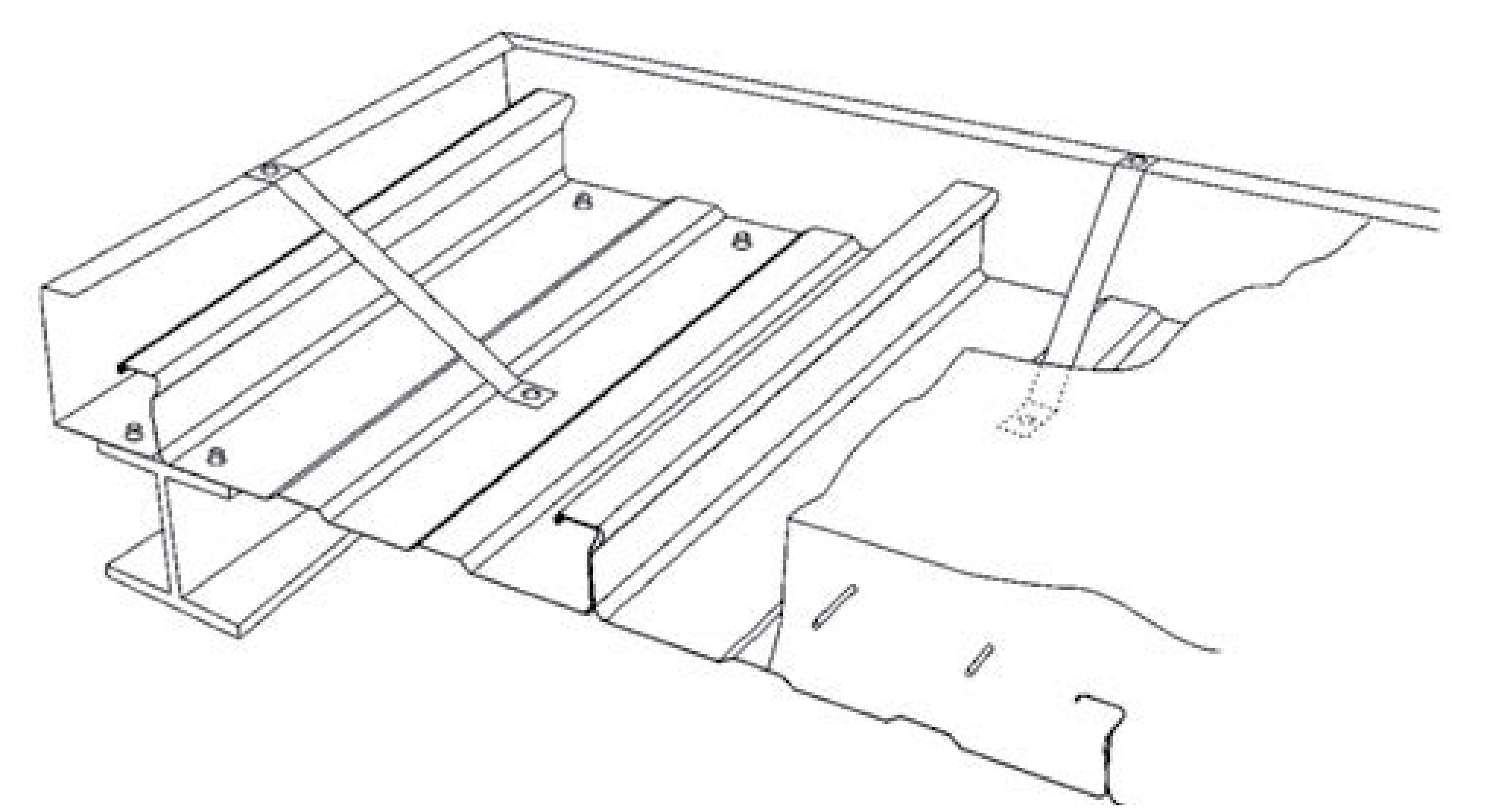
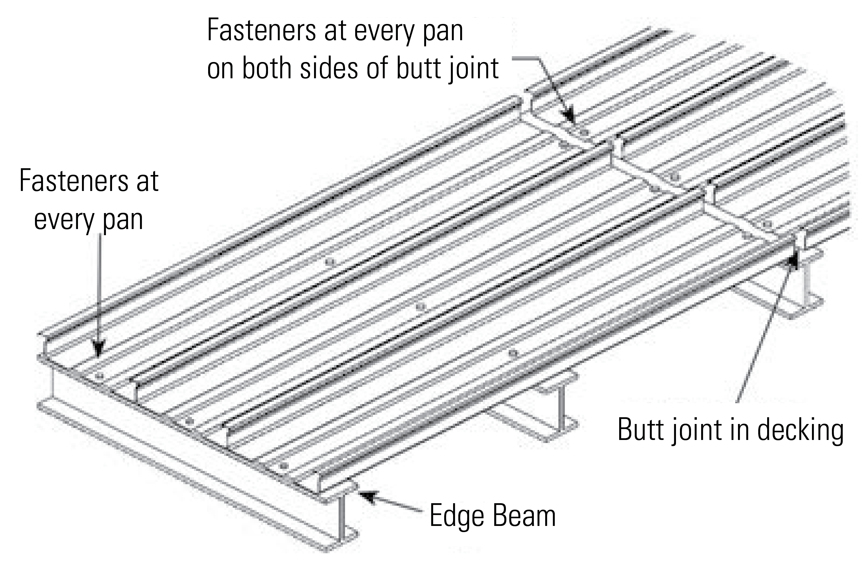
Fasteners and Locations
The decking must be secured to the supporting structure in order to avoid movement and excessive deflection during the pouring of concrete. When fixing to a steel support structure, shot fired pins or self-drilling/tapping fasteners should be used. Provide one fastener in each pan at every support. In the case of other support systems, such as brickwork, block work and concrete, the KF57® sheets must be temporarily held in place against wind and other effects until the concrete is poured.


Reinforcement
Place all reinforcement in strict accordance with the structural engineer’s drawings and specification.

Concrete Placement
The specified grade of concrete and any chemical admixtures must be in strict accordance with AS 3600:2018 and the structural engineer’s drawings and specification. The deck must be clear of any excess dirt, grease or debris as this inhibits bonding between the deck and concrete. Ensure that concrete is applied evenly over the decking surface, as mounding of the wet concrete will cause excessive local loading.
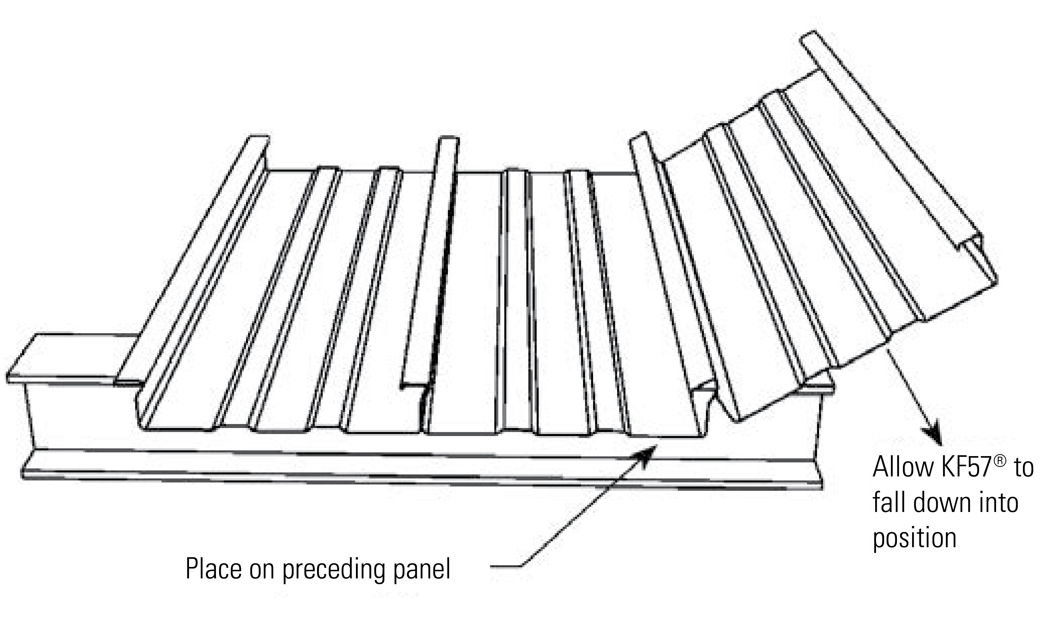
 

Laying KF57®
1. Place the KF57® sheet over the supports ensuring a minimum end bearing of 50mm. If supporting on a brick or masonry wall, provide a separating strip such as malthoid.
2. Engage subsequent sheets of KF57® by locking the larger female rib over the male rib as shown in the diagram below.